Note : Les descriptions sont présentées dans la langue officielle dans laquelle elles ont été soumises.
CA 03146576 2022-01-07
WO 2021/007448 PCT/US2020/041432
DEVICE FOR FEEDING A WIRE ELECTRODE
BACKGROUND
1. Field of the Invention
[0001] The present invention generally relates to systems and devices for
the
feeding of a consumable wire electrode used in gas metal arc welding.
2. Description of Related Art
[0002] Gas metal arc welding (GMAW) is a welding process in which an
electric arc forms between a consumable MIG wire electrode and the
workpiece metal(s), which heats the workpiece metal(s), causing them to melt
and join.
[0003] However, the consumable MIG wire electrode must be fed through the
system in such a manner that the appropriate amount of consumable MIG wire
electrode is provided to the welding torch. An excessive rate of consumable
MIG wire
electrode material feed can cause excessive amounts of material utilized in
bonding
joints, while too low a feed rate of MIG wire electrode material can be
equally
problematic in that the joint may not have enough material to create an
adequate weld,
SUMMARY
[0004] A device for feeding a wire electrode in accordance with an
embodiment of
the present invention includes a housing having an input port, an output port,
and a
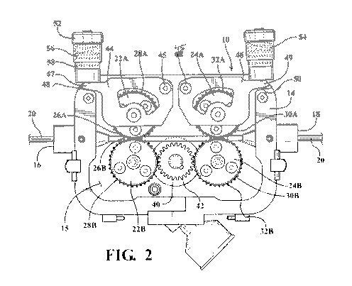
cavity defined by the housing. The input port is configured to receive the
wire electrode,
while the output port is configured to output the wire electrode. The device
also includes
a first group of bearings disposed within the housing comprising at least two
bearings
and a second group of bearings disposed within the housing also comprising at
least
two bearings.
1
CA 03146576 2022-01-07
WO 2021/007448 PCT/US2020/041432
[0005] Each of the bearings have a surface around their outside perimeter
configured to engage the wire electrode. Additionally, each of the bearings
have gear
teeth adjacent to the perimeter of the bearings. The teeth of the bearings
forming the
first group are in meshing engagement with each other, while the teeth of the
bearings
forming the second group are in meshing engagement engagement with each other.
The device also includes a drive sprocket having gear teeth that are
positioned in the
cavity of the housing so as to mesh with the teeth of one of the bearings of
the first
group and the teeth of one of the bearings of the second group.
[0006] In one aspect, the drive sprocket is in mechanical communication
with a
motor disposed outside the cavity, wherein the motor is configured to turn the
drive
sprocket.
[0007] In one aspect, the motor is a pneumatic drive.
[0008] In one aspect, at least one of the bearings of the first group or
one of the
bearings of the second group is mounted to a rotatable frame, wherein the
rotatable
frame has an axis of rotation that is parallel to the axis of rotation to the
bearings of the
first group or the second group.
[0009] In one aspect, the rotatable frame further comprises a biasing
member and
an adjustment device, wherein the biasing member is configured to bias the
rotatable
frame towards the adjustment device.
[0010] In one aspect, the adjustment device is a threaded adjustment
device.
[0011] In one aspect, the adjustment device further comprises a force
sensor, the
force sensor configured to generate a signal indicative of a force between the
biasing
member and the adjustment device.
2
CA 03146576 2022-01-07
WO 2021/007448 PCT/US2020/041432
[0012] In one aspect, each of the bearings define a circumferential surface
configured to engage and drive the electrode in response to rotation of the
bearings.
[0013] In one aspect, the circumferential surface is flat.
[0014] In one aspect, the teeth of each of the bearings are offset axially
from the
circumferential surface.
[0015] In one aspect, the teeth of each of the bearings are disposed on
separate
structure than the circumferential surface.
[0016] In one aspect, a pair of pivotable mounting plates, wherein each of
the
mounting plates supports one of the bearings of the group of bearings for
rotation.
[0017] In one aspect, the mounting plates have an open state and a closed
state,
wherein in the open state the mounting plates are pivoted away from the closed
state to
increase the space between the bearings of each group of bearings.
[0018] In one aspect, at least one sensor is disposed between at least one
of the
mounting plates and a sidewall portion of the housing when the at least one of
the
mounting plates is in the closed state.
[0019] In one aspect, all of the bearings are rotated in response to
rotation of the
sprocket, wherein the sprocket directly contacts and meshes with a first one
bearing of
each group of bearings, and the other bearing of each group of bearings is
directly
contacted and driven by rotation of the first bearing of each group of
bearings.
[0020] In another aspect, a device for conveying a consumable electrode is
provided, including: a first set of bearings including a first primary bearing
and a first
secondary bearing having parallel axes of rotation and defining a space
radially
therebetween configured to receive and convey a consumable electrode; a second
set
3
CA 03146576 2022-01-07
WO 2021/007448 PCT/US2020/041432
of bearings offset relative to the first set of bearings and including a
second primary
bearing and a second secondary bearing having parallel axes of rotation that
are
parallel to the axes of rotation of the first set of bearings and defining a
space radially
therebetween configured to receive and convey the consumable electrode;
wherein
each of the bearings of the first set of bearings and the second set of
bearings define a
circumferential drive surface configured to frictionally engage a consumable
electrode
and a plurality of teeth; wherein each of the bearings of the first set of
bearings and the
second set of bearings include a plurality of teeth, wherein the first primary
bearing is in
direct meshed contact with the first secondary bearing in a first state of the
device and
the second primary bearing is in direct meshed contact with the second
secondary
bearing in a first state of the device; a common drive sprocket in direct
meshed contact
with the first primary bearing and the second primary bearing, wherein
rotation of the
drive sprocket directly rotates the first primary bearing and the second
primary bearing,
and rotation of the first primary bearing and the second primary bearing
directly rotates
the first secondary bearing and the second secondary bearing, respectively,
when the
device is in the first state.
[0021] In one aspect, the first secondary bearing and the second secondary
bearing
are out of meshed contact with the first primary bearing and second primary
bearing,
respectively, in a second state of the device.
[0022] In one aspect, the sprocket remains in direct meshed contact with
the first
and second primary bearings in the second state of the device.
[0023] In another aspect, a method for conveying a consumable electrode is
provided, the method comprising the steps of: rotating a first drive sprocket;
in response
4
CA 03146576 2022-01-07
WO 2021/007448 PCT/US2020/041432
to rotating the first drive sprocket, directly rotating a first primary
bearing and a second
primary bearing via direct meshed contact between the first drive sprocket and
the first
primary bearing and direct meshed contact between the sprocket and the second
primary bearing; in response to rotating the first and second primary
bearings, rotating
first and second secondary bearings via direct meshed contact with the first
and second
primary bearings, respectively; frictionally engaging a consumable electrode
between
the first primary bearing and the first secondary bearing, and frictionally
engaging the
consumable electrode between the second primary bearing and the second
secondary
bearing; driving the consumable electrode in a first direction in response to
the frictional
engagement and concurrent rotation of the first and second primary bearings
and the
first and second secondary bearings.
[0024] In one aspect, the sprocket is rotated in response to actuating a
pneumatic
drive.
[0025] In one aspect, the method includes detecting, via a sensor disposed
in
mechanical communication with at least one of the first secondary bearing and
the
second secondary bearing, a change in force applied to the first secondary
bearing or
the secondary bearing in response to change in the consumable electrode being
conveyed through the device.
[0026] In one aspect, the method includes pivoting the first and second
secondary
bearings out of meshed contact with the first and second primary bearings via
pivotal
movement of mounting plates that support the first and second secondary
bearings for
rotation.
CA 03146576 2022-01-07
WO 2021/007448 PCT/US2020/041432
[0027] Further objects, features, and advantages of this invention will
become readily
apparent to persons skilled in the art after a review of the following
description, with
reference to the drawings and claims that are appended to and form a part of
this
specification.
BRIEF DESCRIPTION OF THE DRAWINGS
[0028] Figure 1 is a perspective view of a device for feeding a consumable
electrode
wire for a gas metal arc welding system in accordance with an aspect of the
disclosure;
[0029] Figure 2 is a front view of an interior of the device, in accordance
with an
aspect of the disclosure;
[0030] Figure 3 is an exploded view of the device in accordance with an
aspect of
the disclosure;
[0031] Figure 4 is a left side isometric view of the device in accordance
with an
aspect of the disclosure;
[0032] Figure 5 is a front isometric view of the device with a front
portion in an open
position illustrating pairs of bearings disposed within a cavity of the device
in
accordance with an aspect of the disclosure;
[0033] Figure 6 is a front isometric view of the device with the front
portion open and
a pair of mounting plates carrying upper bearings pivoted to an open state in
accordance with an aspect of the disclosure;
[0034] Figure 7 is a front view of the device with the front portion
closed, in
accordance with an aspect of the disclosure;
6
CA 03146576 2022-01-07
WO 2021/007448 PCT/US2020/041432
[0035] Figure 8 is front view of the device with the front portion open in
accordance
with an aspect of the disclosure;
[0036] Figure 9 is a top view of the device an illustrating a pneumatic
drive attached
on the rear of the device in accordance with an aspect of the disclosure;
[0037] Figure 10 is a bottom view of the device in accordance with an
aspect of the
disclosure;
[0038] Figure 11 is a left side view of the device in accordance with an
aspect of the
disclosure;
[0039] Figure 12 is right side perspective view of the device illustrating
sensors in
operative communication with a computing device in accordance with an aspect
of the
disclosure;
[0040] Figure 13 is a perspective view of an adjustment mechanism having a
cap,
cylinder, and spring, and having a sensor disposed within the adjustment
mechanism
for detecting changes in the force applied to a corresponding mounting plate;
and
[0041] Figure 14 is a perspective view of an adjustment mechanism in an
open state
and illustrating another sensor disposed on a sidewall portion of the device
and
arranged to be disposed below a tongue portion of the mounting plate.
DETAILED DESCRIPTION OF THE DRAWINGS
[0042] Referring initially to Figures 1 and 2, with additional detail
illustrated through
Figures 1-14, a device 10 for feeding a consumable electrode wire 20 is
provided. The
device 10 has a housing 14 that generally defines a cavity 15. The device 10
includes a
7
CA 03146576 2022-01-07
WO 2021/007448 PCT/US2020/041432
first port 16 and a second port 18, generally located on opposite sides of the
housing
14. The first port 16 is configured to receive the consumable electrode 20,
while the
second port 18 is configured to output the consumable electrode 20. However,
it will be
appreciated that the electrode 20 may be fed in the opposite direction.
[0043] For purposes of discussion, the device 10 may be described as having
an
upper side, lower side, left side, right side, front side, and rear side, as
shown in the
orientation illustrated in Figures 1 and 2. It will be appreciated that these
referenced
directions are for demonstrative purposes, and that the device 10 may be
oriented in
various directions relative to the orientation used for illustration and
demonstration, and
that reference, for example, to upper does not require that a feature be
"above" another
feature in practice.
[0044] With special attention to Figure 2, the device 10 generally includes
a first
group of bearings, such as bearings 22A and 22B, and a second group of
bearings,
which may include bearings 24A and 24B. The bearings may also be referred to
as
bearing pairs, upper and lower bearings, primary and secondary bearings,
and/or the
like. The bearings 22A and 22B are generally located opposite of each other
with the
electrode 20 being located in a space between. This pair of bearings 22A and
22B are
on the left side of the device 10 as shown in Figures 1 and 2, and bearings
24A and
24B are on the right side. The bearings 24A and 24B are also located opposite
of each
other with the electrode 20 being located in the space between as well. The
electrode
20 is sized and arranged to travel within the space between the bearing pairs
22A-B
and 24A-B. Put another way, each pair of bearings is arranged to sandwich the
electrode 20 between the upper and lower bearings of each pair, with rotation
of the
8
CA 03146576 2022-01-07
WO 2021/007448 PCT/US2020/041432
bearings driving the electrode 20 through the device in accordance with the
direction of
rotation of the bearings.
[0045] In another aspect, the bearings 22A and 22B may be disposed such
that
bearing 22A is above 22B as illustrated in Figure 2. Similarly, bearings 24A
and 24B
may be disposed such that bearing 24A is above bearing 24B. The described
spaces
may thereby be disposed vertically between the vertically oppositely disposed
bearings.
[0046] The bearings 22A and 22B of the first group rotate about two
separated axes
that are substantially parallel to each other. As shown in Figure 2, the axes
are spaced
apart and aligned vertically relative to each other as shown in Figure 2. The
bearings
22A and 22B each have surfaces 26A and 26B configured to grip the electrode
20. The
surfaces 26A and/or 26B may be generally concave in shape so as to better
receive the
electrode 20 which may, for example, have a substantially circular and/or
elliptical
cross-section.
[0047] The bearings 22A and 22B also each have a plurality of teeth 28A and
28B
that are configured to engage one another. As such, the bearings 22A and 22B
are in
mechanical gear meshing engagement with each other such that when one of the
bearings turn, the other meshed bearing will also turn, but in the opposite
rotational
direction. This turning of the bearings 22A and 22B essentially feeds the wire
through
the device 10, as the surfaces 26A and 26B frictionally engage the electrode
wire 20
and drive the electrode wire 20.
[0048] The same is generally true for the second group of bearings 24A and
24B.
The bearings 24A and 24B of the second group rotate about two separated axes
that
are substantially parallel to each other and vertically spaced. The bearings
24A and 24B
9
CA 03146576 2022-01-07
WO 2021/007448 PCT/US2020/041432
each have surfaces 30A and 30B configured to grip the electrode 20. The
surfaces 30A
and/or 30B may be, for example generally concave in shape so as to better
receive the
electrode 20 which may have a substantially circular and/or elliptical cross-
section.
[0049] The bearings 24A and 24B also each have a plurality of teeth 32A and
32B
that are configured to mesh with each another. As such, the bearings 24A and
24B are
in mechanical gear meshing engagement with each other such that when one of
the
bearings turn, the other bearing will also turn, but in the opposite
rotational direction.
[0050] This turning of the bearings 24A and 24B essentially feeds the wire
20
through the device 10, as the surfaces 30A and/or 30B frictionally engage the
electrode
wire 20.
[0051] As described in further detail below, the bearings 22A-B and 24A-B
may be
actively driven or turned by the device 10 to feed the electrode 20 through
the device
10. Put another way, the bearings 22A-B and 24A-B may be considered active
bearings rather than passive bearings that rotate in response to
pushing/pulling the
electrode 20 via other mechanisms.
[0052] As described above, the bearings 22A-B and 24A-B define spaces
therebetween through which the electrode 20 may be fed. The spaces are defined
by
the opposing surfaces 26A-B and 30A-B. The surfaces, in one aspect, may be
concave
therefore providing for feeding an electrode 20 with a convex outer profile,
such as
circular or elliptical as described above.
[0053] The concave curvature defined by the surfaces of the bearings 22A-B
and
24A-B may be defined to have a larger curvature or radius than that of the
electrode 20,
CA 03146576 2022-01-07
WO 2021/007448 PCT/US2020/041432
such that the electrode may be in contact with the lowermost or uppermost
portion of
the curved surface.
[0054] In another aspect, the surfaces of the bearings 22A-B and 24A-B may
be U-
shaped and may define a flat surface against which the electrode 20 may bear.
It will
be appreciated that other curvatures or surface profiles may be used for the
bearings
22A-B and 24A-B in some embodiments that may operate to frictionally engage
the
electrode for driving and feeding the electrode 20 through the device 10.
[0055] In one aspect, the teeth 28A, 28B, 32A, 32B of the bearings may be
axially
offset from the drive surfaces 26A, 26B, 30A, 30B of the bearings, as shown in
Figures
and 6. In one aspect, the teeth 28A, 28B, 32A, 32B may be generally disposed
adjacent the rear of the cavity 15, with the surfaces disposed in the middle
of the cavity
and aligned with the direction of the electrode 20 as defined by the inlet 16
and outlet
18 through which the electrode 20 is drawn.
[0056] As shown in Figures 5 and 6, the surfaces 26A, 26B, 30A, 30B may be
generally flat surfaces rather than concave surfaces, and may, in one aspect,
include
circumferential grooves. Such flat surfaces may be disposed spaced apart
vertically
from each other to accommodate the thickness of the electrode 20 when the
electrode
is passing through the space and between the surfaces 26A, 26B, 30A, 30B.
[0057] The teeth 28A, 28B, 32A, 32B may be disposed on a separate disc-like
structure that is attached to another separate disc-like structure that
defines the
surfaces 26A, 26B, 30A, 30B. Thus, the bearings 22A, 22B, 24A, 24B may be in
the
form of a multi-piece structure that is fixedly joined and secured together.
This multi-
piece approach may be used to alter the strength and/or stiffness and/or
friction
11
CA 03146576 2022-01-07
WO 2021/007448 PCT/US2020/041432
qualities of the surfaces 26A, 26B, 30A, 30B that engage the electrode 20,
which may
be different than the material qualities of the teeth 28A, 28B, 32A, 32B that
are meshed
engagement and undergoing different forces. However, in another approach, the
teeth
28A, 28B, 32A, 32B and the surfaces 26A, 26B, 30A, 30B that drive the
electrode 20
may be part of the same unitary structure.
[0058] With reference again to Figure 2, central sprocket 40 is also
disposed within
the cavity 15, and is configured to drive the bearings 24A-B and 26A-B. The
central
sprocket 40 has a plurality of external gear teeth 42 adjacent or near the
perimeter of
the central sprocket 40. The sprocket 40 is illustrated as a spur gear that
engages the
bearing 22B and 24B. However, it will be appreciated that other gear types may
also be
used that engage one or both gears 22B and 24B. In one aspect, the sprocket 40
may
also be referred to as a driving gear system 40, which may include other gear
types or
gear mechanism, including reduction gearsets, such that intermediate gears may
be
disposed between sprocket 40 and the gears 22B and 24B.
[0059] The teeth 42 of the central sprocket 40 are arranged such that they
mesh with
the teeth 28B of bearing 22B and mesh with the teeth 32B of the bearing 24B.
As such,
when the central sprocket 40 rotates, the central sprocket then drives both
bearings 22B
and 24B directly. From there, bearings 22B and 24B drive bearings 22A and 24A,
respectively. Put another way, the bearings 22B and 24B are directly driven by
rotation
of the sprocket 40, and bearings 22A and 24A are indirectly driven by the
sprocket 40.
The bearings 22A and 24A are then directly driven by the bearings 22B and 24B,
respectively. Thus, the bearing 22B and 24B may be considered primary
bearings, and
the bearings 22A and 24A may be considered secondary bearings.
12
CA 03146576 2022-01-07
WO 2021/007448 PCT/US2020/041432
[0060] The sprocket 40 is arranged to be engaged with the bearings 22B and
24B at
all times via the meshed engagement. Put another way, the sprocket 40 is
common
driving mechanism for both the bearings 22B and 24B. Rotation of the sprocket
40
therefore inherently drives both bearings 22B and 24B. When bearing 22B
rotates,
bearing 24B also rotates because they are both meshed with the sprocket 40.
Put
another way, bearings 22B and 24B rotate concurrently.
[0061] In one aspect, bearings 22B and 24B are arranged to rotate in the
same
rotational direction concurrently. As shown in Figure 2, sprocket 40 is
meshingly
directly engaged and in contact with the bearings 22B and 24B and is disposed
laterally
between and/or axially offset and between the bearings 22B and 24B.
[0062] In one aspect, the sprocket 40 rotates about an axis that is
parallel to the
axes of rotation of the bearings 22A-B and 24A-B. However, in another aspect,
the
sprocket 40 may be in the form of a worm, helical, bevel, or other gear type
such that
the axis of the sprocket may be arranged non-parallel to the axes of rotation
of the
bearings.
[0063] A motor 12, that is generally disposed outside of the housing 14 but
could, in
some examples, be disposed within the cavity 15 of the housing 14, functions
to drive
the central sprocket 40. As such, because only the central sprocket 40 is
directly turned
by the motor 12, the central sprocket 40 essentially functions so as to
provide a drive
turning force to the bearings 22A, 22B, 24A, and 24B. The motor 12 may be any
type of
device capable of providing a rotational output force to the central sprocket
40. As such,
the motor 12 could be any type of motor, such as, as examples, electric,
internal
combustion, pneumatic, or hydraulic motor. In a preferred aspect, the motor 12
is
13
CA 03146576 2022-01-07
WO 2021/007448 PCT/US2020/041432
pneumatic motor including an air inlet 12a configured for attachment to a
supply of
pressurized air. Provision of pressurized air into the motor 12 can drive the
output shaft
and the sprocket 40 in the desired rotational direction. The air inlet 12a may
be
selectively moveable on the motor 12 to control the direction of rotation of
the output
shaft of the motor 12.
[0064] Figure 1 illustrates a motor housing 13 extending outwardly from the
device
housing 14. In one aspect, the motor housing 13 may be considered part of the
device
housing 14. The motor housing 13 may be secured to the device housing 14, with
an
opening in the device housing 10 providing access to an output shaft of the
motor 12 to
which the sprocket 40 is rotationally fixed.
[0065] The device housing 10 may include a front portion 14A and a rear
portion
14B, which may have a generally plate-like shape. The device housing 10 may
further
include a sidewall portion 14C that extends between the front portion 14A and
the rear
portion 14B and which may have a U-shape that is open at the top. The sidewall
portion 14C may be in the form of two pieces joined together at the bottom, in
one
aspect, as shown through the figures. The front portion 14A may be attached to
the
sidewall portion 14C via clips 11A and a hinge 11B, thereby permitting
selective access
to the interior of the device 10 by opening the front portion 14A. The front
portion 14A
may include a transparent or translucent window portion 11C for viewing the
interior of
the device.
[0066] During operation of the motor 12, the sprocket 40 is rotated in a
first rotational
direction. For example, the sprocket may be rotated counter-clockwise in
Figure 2.
Due to the meshed engagement with both bearings 22B and 24B, the bearings 22B
and
14
CA 03146576 2022-01-07
WO 2021/007448 PCT/US2020/041432
24B rotate in a second rotational direction that is opposite the first
rotational direction,
for example clockwise in Figure 2 when sprocket 40 rotates counter-clockwise.
Such
rotational direction drives the electrode 20 to the right in Figure 2.
[0067] The direct meshed engagement between the sprocket 40 and the bearings
22B and 24B thereby results in the linear velocity at the perimeter of the
sprocket 40
and the bearings 22B, 24B to be effectively the same. The angular velocity of
these
meshed and rotating components may vary depending on the relative diameters of
the
components. In one aspect, the diameters of the bearings 22B and 24B are the
same,
such that they rotate at the same angular velocity relative to each other. In
one aspect,
the sprocket 40 has the same diameter as the bearings 22B, 24B such that they
rotate
at the same angular velocity.
[0068] This arrangement of a single motor 12 and sprocket 40 has certain
advantages in that separate motors do not need to be utilized to drive the
bearings 22A,
22B, 24A, and 24B. Thus, separate motors do not need to be controlled to
rotate at the
same rate to create corresponding feed rates for the bearings. By utilizing
only one
motor, cost savings can be realized as well that the 22A, 22B, 24A, and 24B
will each
turn in unison limiting issues with the feeding of the consumable electrode
wire 20
through the device 10.
[0069] Additionally, the use of the two bearings 22B and 24B rotating at
the same
rate to the feed the electrode 20 thereby creates a redundancy in the event
one bearing
slips relative to the electrode 20 or the electrode shifts out of engagement
with the
bearings.
CA 03146576 2022-01-07
WO 2021/007448 PCT/US2020/041432
[0070] The bearing 22A and/or bearing 24A may be mounted within the cavity
15 by
utilizing mounting plates 44 and 46, respectively. The mounting plates 44 and
46 may
have an axis of rotation defined by mounting screws 45. Put another way, the
mounting
plates 44 and 46 may be permitted to pivot about mounting screws 45. This
pivotable
movement allows for the bearings 22A and 24B to be taken out of engagement
with the
bearings 22B and 24B. It will be appreciated that the mounting screws 45 may
also be
in the form of pins or rivets or other axially arranged securing mechanism
that retains
the mounting plates 44 and 46 within the cavity while allowing for pivotal
movement
about the screws 45. The mounting plates 45 may be sized and arranged in a
symmetrical manner within the cavity 15, and may effectively be a mirror-image
of each
other when installed within the cavity.
[0071] In one aspect, the mounting plates 44, 46 may in the form of a
hollow
member or frame with opposing flange portions 44A, 44B, 46A, 46B (such as
front and
rear portions) that are disposed on opposite axial sides of the bearings 22A
and 24A. A
pin or other axial structure may extend axially between the front/rear
portions for
supporting the bearings 22A and 24A for rotation.
[0072] Each of the mounting plates 44 and 46 may have a tongue portion 47
and 49
respectively. Each of the tongue portions 47 and 49 may be biased by biasing
members
48 and 50 towards adjustment mechanisms 52 and 54, respectively. The tongue
portions 47 and 49 are configured to pivot up and away from the biasing
members 48,
50 about the mounting screws 47 and 47. In another aspect, the biasing members
48
and 50 may be excluded, and the tongue portions 47 and 49 may directly contact
an
upper edge of sidewall portion 14C. The tongue portions 47 and 49 may be
spaced
16
CA 03146576 2022-01-07
WO 2021/007448 PCT/US2020/041432
apart from the upper edge/surface of the sidewall portion 14C due to the
electrode 20
being disposed between the respective contact surfaces of the bearing pairs
when the
mounting plates 44 and 46 are in a lowered position and secured by the
adjustment
mechanisms 52 and 54. The upper edge surface of the sidewall 14C may be
tapered
with the tongue portions 47 and 49 having a corresponding tapered surface that
faces
the upper edge of the sidewall 14C.
[0073] The adjustment mechanisms 52 and 54 may be thumbscrew type adjustment
mechanisms that allow one to provide an opposing force to the tongue portions
47 and
49 of the mounting plates 44 and 46, respectively. This opposing force opposes
the
force provided by the biasing members 48 and 50 or other reaction force. As
such, the
adjustment mechanisms 52 and 54 allow one to adjust the space located between
the
bearings 22A and 22B and the space between 24A and 24B, respectively.
[0074] The adjustment mechanisms 52 and 54 may be pivotally fixed to the
side
portion 14C of the housing 14 of the device 10, allowing the adjustment
mechanisms 52
and 54 to be pivoted away from and out of engagement with the tongue portions
47, 49,
such that tongue portions 47 and 49 may be pivoted upward to provide access
within
the housing 14, as shown in Figure 6. To secure the tongue portions 47, 49
against the
housing 14, the tongue portions 47, 49 may be pivoted back into position
against the
biasing members 48, 50, and the adjustment mechanisms may be pivoted such that
they are disposed over the tongue portions 47, 49, and can be adjusted and
tightened
to apply a force on the tongue portions 47, 49 against the biasing members, as
shown
in Figure 5.
17
CA 03146576 2022-01-07
WO 2021/007448 PCT/US2020/041432
[0075] The mounting plates 44 and 46 may therefore be moveable between an open
state (Figure 6) and a closed state (Figure 5). Similarly, the adjustment
mechanism are
moveable between an open state (Figure 6) and a closed state (Figure 5).
[0076] The adjustment mechanism 52, 54 may include a spring 55A disposed
within
a cylinder 55B and a cap 55C that is adjustable relative to the cylinder 55B.
Adjustment
of the cap 55C may cause the cylinder 55B to be forced up/down in combination
with
the bias of the spring 55A. Alternatively, the cylinder 55B may simply be
slidable
relative to the cap 55B, with the spring 55A biasing the cylinder into
engagement with
the tongue portion 47, 49 to secure the tongue portions 47, 49 in the closed
state when
the adjustment mechanisms 52, 54 are moved to the closed state.
[0077] The rear portion 14B of the housing 14 may include curved slots 51
that may
receive the pins that support the bearings 22A, 24A. Thus, when the mounting
plates
44, 46 pivot upward about screws 45, the pins may travel along the slots 51
along a
radiused, curved path defined by the slots 51.
[0078] In addition, the space located between the bearings 22A and 22B and
the
space located between the bearings 24A and 24B may vary as the device 10 is
used.
Moreover, in situations where the electrode 20 has been completely spent and
is no
longer located within the cavity 15, the tongue members 47 and/or 49 may move
slightly
and provide a different force applied to the adjustment mechanisms 52 and 54
respectively. Additionally, in situations where there is an issue with the
feeding of the
electrode 20 through the device 10, such as a knot or imperfection in the
electrode, an
opposing force may be applied against the adjustment mechanisms 52 and 54,
respectively. The lack of force from the absence of an electrode 20 or the
increased
18
CA 03146576 2022-01-07
WO 2021/007448 PCT/US2020/041432
force from the imperfection or knot can be detected by a control system 200
(Figure 12)
or other computing device having instructions and software algorithms for
detecting
changes in force via the use of sensors 58, 158 in operative communication
with the
control system 200 via signals or other communication methods.
[0079] For these types of situations, sensors 58 and/or 158 may be
provided, as
shown in Figures 12-14. In one aspect, shown in Figures 12 and 13, the
adjustment
mechanisms 52 and 54 may include force sensor 58. The force sensor 58 may be
disposed within the adjustment mechanism and is capable of measuring the force
applied to the adjustment mechanism 52 by the tongue portion 47 of the
mounting plate
44. By monitoring signals generated by the force sensor 58 indicative of the
force
applied to the adjustment mechanism 52, one can electronically monitor issues
or
problems that may arise during the use of the device 10, such as issues when
the
electrode 20 is completely spent and/or issues regarding to imperfections with
the
electrode 20 or malfunction of the device 10.
[0080] In another aspect, shown in Figures 12 and 14, force sensors 158 may
be
disposed outside of the adjustment mechanisms 52, 54, and may be disposed
between
one or both of the tongue portions 47, 49 and the side portion 14C of the
housing 14.
For example, as shown in Figure 14, force sensor 158 may be disposed on a top
end of
the sidewall portion 14C, such that when the tongue portion 47 or 49 is
tightened by
adjustment mechanism 52 or 54, the force sensor 158 will detect a reaction
force.
During operation of the feeding of the electrode 20, the force detected by the
force
sensor 158 may be monitored via control system 200. If an imperfection or knot
passes
through the bearings of the device 10, the tongue portions 47, 49 will be
pushed
19
CA 03146576 2022-01-07
WO 2021/007448 PCT/US2020/041432
upward, reducing the force applied to the force sensor 158. Similarly, if the
electrode 20
is spent and the tongue portion is no longer being forced upward by the
presence of the
electrode, the adjustment mechanism 52, 54 may apply a greater force onto the
force
sensor 158.
[0081] As a person skilled in the art will readily appreciate, the above
description is
meant as an illustration of an implementation of the principles of this
invention. This
description is not intended to limit the scope or application of this
invention in that the
invention is susceptible to modification, variation, and change, without
departing from
the spirit of this invention, as defined in the following claims.