Note : Les descriptions sont présentées dans la langue officielle dans laquelle elles ont été soumises.
2020P00150CA
IMMERSION DEVICE FOR TEMPERATURE MEASUREMENT AND METHOD FOR
POSITION DETECTION
DESCRIPTION
The invention relates to an immersion device for measuring a temperature of a
metal
melt inside an electric arc furnace (EAF) vessel using an optical cored wire
and a
method for detecting a position of an optical cored wire using an immersion
device.
Metallurgical processes can be performed in an arc furnace as disclosed in US
2886617 A, in particular in an EAF. To improve process control, the
temperature of a
metal melt has to be measured. This can e.g. be performed by means of an
optical
fiber which is immersed into the melt and a corresponding detector connected
to the
fiber, as described in EP 2 799 824 Al, EP 3 051 264 Al and EP 2 799 824 Al.
The
optical fiber itself is coated with metal. In the mentioned processes, the
optical fiber is
introduced into a disposable guiding tube before the measurement. At least a
part of
the guiding tube melts during use. To determine the quality of the temperature
measurement, the position of the optical fiber with the guiding tube inside a
feeding
means can be monitored. JPH09304185 A discloses a metallic sheath optic fiber
for
measuring the temperature of molten steel, wherein a sent length of the optic
fiber is
measured by a motor with an encoder. A similar device is known from
JPH07151608 A.
In another process, the optical fiber may be provided as a virtually endless
tube which
is wound on a coil and unwound for conducting a measurement. A feeding device
for
such an optical fiber is described in EP 3 051 262 Al. EP 2 940 441 Al
describes a
device for temperature measurement with a gap between the optical fiber and a
guiding
tube. An alternative approach is described in JPH09243459 A, wherein the fiber
is cut
to define a known leading end position.
It is the task of the present invention to improve the temperature measurement
in a
vessel of an electric arc furnace.
The task of the invention is solved by an immersion device according to claim
1 and a
method for detecting a position of an optical cored wire according to the
additional
claim. Advantageous embodiments are defined in the dependent claims.
Date Recue/Date Received 2022-01-26
2020P00150CA
2
The task is solved by an immersion device for measuring a temperature of a
metal melt
inside an electric arc furnace vessel with an optical cored wire. The
immersion device
comprises a blowing lance for blowing purge gas into an entry point to the
vessel and a
detecting means for detecting a position of the optical cored wire. The
immersion
device is configured such that the optical cored wire can be moved in a
feeding
channel and/or in the blowing lance relative to the entry point. The detecting
means is
configured to detect the presence of the optical cored wire in or close to the
blowing
lance.
As the leading end of the optical cored wire melts during temperature
measurement, its
position has to be determined before each temperature measurement. In
conventional
solutions, the position of the optical cored wire is detected in the feeding
tube and,
thus, at a position that is comparably far away from the vessel. Therefore,
the optical
cored wire has to be moved a long way back and forth between temperature
measurement and position measurement which is time-consuming. Thus, using
conventional techniques, the interval between two temperature measurements is
long.
Detecting the presence of the optical cored wire in or close to the blowing
lance leads
to faster transport of the optical cored wire and, thus, enables a shorter
time interval
between measurements. This is of particular importance as the temperature of
the
liquid steel bath during EAF operation can change at rates of up to 70 C per
minute.
More measurements can be performed, thus enabling a better process control.
The
distance of the leading end to the melt can be kept significantly lower. In
addition,
debris or wear caused by the returning hot optical cored wire can always
pollute and
damage or block the tubing. By reducing the movement path of the optical cored
wire
inside the feeding channel, this risk can be minimized. As according to the
invention,
the movement of the leading end of the optical cored wire can be limited to
the blowing
lance which can easily be replaced, a simple solution is enabled in case of
pollution or
damage. The part of the detecting means which gets close to the hot optical
cored wire
can be easily replaced. In addition, the temperature measurement becomes more
reliable because the leading end can be immersed on the best landing point.
A blowing lance is a lance through which purge gas can be blown into the
vessel. This
can help prevent penetration of metal, slag and/or debris into the feeding
channel. The
blowing lance may be replaceable. Typically, the blowing lance is straight,
i.e. not
Date Recue/Date Received 2022-01-26
2020P00150CA
3
curved, for feeding the optical cored wire along a straight path towards the
melt. The
blowing lance may be manufactured in one piece. The blowing lance is in
particular
arranged coaxial to the feeding channel and/or axially adjacent to the feeding
channel.
In particular, the feeding channel adjoins the blowing lance in the direction
away from
the vessel. A part of the detecting means for detecting the presence of the
optical
cored wire may be arranged on the blowing lance. A part of the detecting means
may
be arranged close the blowing lance, e.g. on the feeding channel, near a
connection of
the blowing lance and the feeding channel and/or between blowing lance and
feeding
channel.
The blowing lance may serve for guiding the optical cored wire into the melt
and/or out
of the melt inside the vessel. The purge gas cools the blowing lance and/or
the optical
cored wire therein. During a measuring sequence, the optical cored wire can be
moved
inside the feeding channel and the blowing lance towards the melt.
The feeding channel serves for feeding the optical cored wire into the vessel
and/or out
of the vessel. The feeding channel defines a straight and/or curved path along
which
the optical cored wire can be moved. In particular, the moving means is
configured for
moving the optical cored wire along the path defined by the feeding channel.
The
feeding channel is in particular closed and/or has a circular cross-section.
It may
comprise a feeding tube, e.g. a metal tube, i.e. a tube through which the
optical cored
fiber can be fed. The feeding channel may be formed by metal walls. It may
have an
inner diameter above 7 mm, in particular above 9 mm, and/or below 15 mm, in
particular below 12 mm. The device may comprise the feeding channel. The
feeding
channel and the blowing lance can together be referred to as feeding system.
The
feeding system may further comprise the detecting means or the detector.
The optical cored wire comprises an optical fiber which may be e.g. a glass
fiber. The
optical fiber may be a graded index fiber with a diameter of 50 pm or 62.5 pm.
In
particular, the optical cored wire comprises a metal tube arranged around the
fiber, i.e.
it is a metal coated optical fiber, also referred to as FiMT (Fiber in a Metal
Tube). The
metal tube may have an outer diameter of more than 1 mm, in particular 1.3 mm
and/or
less than 3 mm, in particular 2.5 mm. The wall thickness of the metal tube may
be
more than 0.1 mm and/or less than 0.3 mm, in particular less than 0.2 mm. The
optical
cored wire may further comprise an outer tube arranged around the metal tube.
The
Date Recue/Date Received 2022-01-26
2020P00150CA
4
outer tube may be made of metal. It may have an outer diameter of more than 4
mm
and/or less than 8 mm, in particular approx. 6 mm. The wall thickness of the
outer tube
may be more than 0.2 mm, in particular more than 0.3 mm, and/or less than 0.7
mm, in
particular less than 0.5 mm.
The leading end of the optical cored wire is the end which is immersed into
the melt in
order to measure the temperature. The position of the leading end of the
optical cored
wire typically corresponds to the position of the leading end of the optical
fiber. In
particular, the optical cored wire is consumed in the direction from the
leading end
towards the other, opposite end. After each measuring sequence, another part
of the
optical cored wire will be the leading end. The other end may be connected
with a
detecting unit to evaluate signals measured and/or transported by the optical
cored
wire to determine the temperature. The other end will not be consumed during a
measurement. The detecting unit may be configured to receive a light signal,
in
particular in the IR wavelength range, transmitted by the optical fiber. The
detecting
unit may be a pyrometer.
Detecting a presence of the optical cored wire means detecting an information
relating
to whether or not the optical cored wire is present at a certain position.
This helps
detect the position of the optical cored wire. In particular, the presence of
the optical
cored wire at a defined position of the blowing lance and/or the feeding
channel can be
detected. This can be realized in that a part of the detecting means is
positioned in a
known fixed position relative to the feeding channel and/or blowing lance. In
particular,
the detecting means is configured to detect the presence of the optical cored
wire in a
position which has a distance less than 4 m, in particular less than 2 m and
in one
embodiment less than 1 m of an outer wall of the EAF vessel. In particular,
the
detection position is above the outer wall. Preferably, the detecting means is
configured
to detect the presence of the optical cored wire in a position which has a
distance less
than 1 m, in particular less than 50 cm and in one embodiment less than 20 cm
of the
blowing lance. The detection position may be above the blowing lance. The
distance to
the blowing lance is in particular an axial distance.
The immersion device is in particular installed in a stationary manner. In
particular, the
immersion device is configured such that it can be positioned on an outer wall
of the
vessel or on a platform on a side of the vessel, if present. If positioned on
an outer wall,
Date Recue/Date Received 2022-01-26
2020P00150CA
the immersion device may be installed on an eccentric bottom tap (EBT)
platform or at
a side wall of the vessel. The optical cored wire may thus be moved downwards
into
the vessel from the stationary point. The platform may be a part of the side
wall and/or
essentially horizontally aligned. In particular, the entry point of the vessel
is positioned
5 on the platform and/or is an essentially vertically aligned opening.
In one configuration, the detecting means comprises an inductive sensor for
detecting
the presence of the optical cored wire. The inductive sensor may be arranged
on or
close to the blowing lance. For example, it may be arranged on the feeding
channel
and/or a feeding tube. Two inductive sensors may be used to determine the
position of
the leading end therebetween.
In one embodiment, the detecting means comprises a detector for measuring a
property of a gas flow. In particular, the detector is configured for
measuring a flow rate
of the gas flow, a flow velocity of the gas flow and/or a gas pressure in the
gas flow.
Thus, a gas flow is used to detect the presence of the optical cored wire. In
particular, a
gas flow is realized in or close to the blowing lance such that the presence
of the
optical cored wire influences the gas flow, e.g. by obstructing at least a
part of the flow
path of the gas flow. By measurement of the property, the presence of the
optical cored
wire can be detected. The device may comprise a suitable gas source. The
detector
may be positioned close to the blowing lance or at a remote position, being
connected
with a gas line. Typically, gas lines are highly temperature-resistant.
The term gas in the context of the invention refers to any gaseous material,
e.g. a gas,
a gas mixture and/or a dispersion having gas as continuous medium. Thus, a gas
flow
may be a flow of mixture of gases such as air.
This embodiment enables a durable and highly temperature resistant position
detection. During use as intended, the position in or close to the blowing
lance is
subjected to adverse conditions, including high temperatures of several
hundred
degrees Celsius, flames and sparks due to the proximity of the EAF vessel.
This
embodiment dispenses with electric or electronic components in the heat zone
and is
thus particularly robust. The technical effort is low as no shielding or heat
protection is
necessary. It should further be noted that the leading end of the optical
cored wire of
which the position is to be detected has been in the liquid metal a second
before the
Date Recue/Date Received 2022-01-26
2020P00150CA
6
detection. It has shown that gas flow properties are robust and accurately
detect the
presence of the optical cored wire in the hot state. In addition, a
particularly fast
detection of leading end is enabled.
In one embodiment, the immersion device comprises a moving means for moving
the
optical cored wire in the feeding channel and/or in the blowing lance relative
to the
entry point. The moving means moves the optical cored wire relative to the
feeding
channel and/or the blowing lance and along the longitudinal extension of the
feeding
channel or the blowing lance. The moving means is in particular configured to
move the
.. optical cored wire such that the leading end is moved into the vessel and
out of the
vessel and/or into a melt contained in the vessel and out of the melt. The
moving
means may thus be configured for a forward movement and/or a backward movement
of the optical cored wire. The movement of the optical cored wire is in
particular a
movement along a straight or curved path. The moving means may comprise a
motor.
In a further embodiment, the moving means is configured for feeding the
optical cored
wire from a coil and/or for winding unused optical cored wire back on the
coil.
It has been shown that the position measurement close to the vessel functions
particularly well using coiled optical cored wire. Also, the used wire types
can reliably
be monitored by gas flow detection. This embodiment enables a reliable and low-
effort
way of providing a great (virtually infinite) length of optical cored wire for
a great
number of measurements. Thus, the high frequency of temperature measurements
can
be performed over at least one whole EAF operation cycle, thus enabling a
maximum
process control.
In a further embodiment, the feeding channel and/or the blowing lance has a
first
opening and/or a second opening. A gas supply means can be connected with the
first
opening for introducing pressurized gas into the first opening. The detector
may be
connected with the second opening by means of a detector line.
In particular, the first opening and/or the second opening is a radial opening
with
respect to the longitudinal extension of the feeding channel and/or the
blowing lance. In
particular, the two openings are located on the same axial position with
respect to the
.. longitudinal extension of the feeding channel or blowing lance. A gas flow
realized
Date Recue/Date Received 2022-01-26
2020P00150CA
7
through the openings is influenced by the optical cored wire and the detecting
means
can detect a property of the gas flow in order to detect influence and, thus,
the
presence or absence of the optical cored wire. Using the openings, it can be
detected
whether or not the optical cored wire is present between the openings. Thus,
an
information is derivable whether the leading end of the optical cored wire is
on the
vessel side or the opposite side of the openings.
The term "connect" or "connection" relates to flow connections in order to
enable the
respective gas flows. The detector line is a fluid connection between the
detector and
the second opening. As a rule, a line in the sense of the invention means a
fluid
connection independent of the type which may e.g. be a pipe, a tube or the
like.
This embodiment has shown reliable results even in case that the radial
position of the
optical cored wire in the feeding channel or blowing lance is not known due to
a radial
gap between an outer diameter of the optical cored wire and the respective
inner wall.
When the leading end passes the position between the openings, a jump in the
property, e.g. flow or pressure, can be observed. Further, this embodiment
enables a
particularly reliable and disturbance-free operation.
In a further embodiment, the first opening and the second opening are aligned
coaxially
and/or arranged on opposite positions of the cross-section of the feeding
channel or
the blowing lance, respectively. In other words, the openings share a common
axis.
This axis may run perpendicular to the feeding channel axis. Thus, a direct
gas flow
can be established between the openings, enabling a particular precise
position
detection. The openings may be arranged on opposing sides of the feeding
channel
with the channel diameter between them, thus making use of the complete cross-
section.
In a further embodiment, the feeding channel has a straight portion positioned
adjacent
to the blowing lance and a bent portion positioned adjacent to the straight
portion. The
first opening and the second opening may be positioned close to a location in
which the
straight portion and the bent portion meet. Alternatively, the blowing lance
is straight
such that the optical cored wire can be fed along a straight path towards the
vessel and
the feeding channel has a bent portion positioned adjacent to the blowing
lance. In this
Date Recue/Date Received 2022-01-26
2020P00150CA
8
case, the first opening and the second opening may be positioned close to a
location in
which the blowing lance and the feeding channel meet.
The straight portion is directed towards the vessel and/or between the bent
portion and
the vessel. Thus, the optical cored wire can be introduced along a straight
path into the
melt and back from the melt without being bent. The mechanical properties of
the
optical cored wire change due to the heat which the optical cored wire is
subjected to
during temperature measurement and/or the subsequent cooling. In particular,
its
flexibility decreases. Moving the optical cored wire without bending avoids
permanent
deformation and, thus, wear, stress and friction of the optical cored wire,
ingress of
material from the vessel and blocking of the feeding system. Further movement
of the
optical cored wire is prevented.
The bent portion is positioned on the side of the straight portion facing away
from the
vessel. Thus, the space requirement of the device can be minimized.
The two openings are positioned close to the meeting location. In particular,
an axial
distance of any of the two openings to the meeting location with respect to
the
longitudinal direction of the feeding channel and/or the blowing lance is less
than
25 cm, preferably less than 15 cm. In one configuration, said axial distance
is below
5 cm or zero.
In one embodiment, the immersion device comprises a purge gas line for
connecting a
high-pressure gas source to the blowing lance in order to generate a first
purge gas
flow in the blowing lance towards the vessel and/or the melt contained
therein. The
high-pressure gas source provides a gas or gas mixture at a pressure of at
least 5 bar,
in particular at least 10 bar. The purge gas line is thus configured to
withstand a
pressure in the mentioned order. It is preferably designed as a tube and/or
made of
metal. The purge gas flow serves for keeping the hollow space within the
blowing lance
free of debris from the vessel and ensures reliable operation of the cored
wire. This
helps keeping the feeding channel free of slag and frozen metal from the
vessel and,
thus, ensures disturbance-free operation.
In a further embodiment, the purge gas line is connected to a flow divider for
dividing a
gas flow from the high-pressure gas source to two lines. A first line is
connected to the
Date Recue/Date Received 2022-01-26
2020P00150CA
9
blowing lance to generate the first purge gas flow and a second line is
connected to the
first opening. In other words, a single high-pressure gas source is used for
both the
purge gas flow and the position detection. Thus, an already present gas source
can be
used for detecting the position of the optical cored wire which minimizes the
technical
effort. The first line and/or the second line may be made of metal and/or
designed as a
tube. The first line and/or the second line may be very short and/or designed
as a gas
passage or opening for gas to pass through.
In a further embodiment, the immersion device comprises a detector line
purging line
which connects the purge gas line with the detector line in order to generate
a second
purge gas flow in the detector line through the second opening into the
blowing lance
or the feeding channel. In particular, a periodic and/or temporary gas flow is
generated
to purge the detector line. Thus, the detector line can be kept free of
debris. In other
words, the gas flow in the detector line can be reversed. A switching valve
may be
arranged within the detector line purging line such that the second purge gas
flow can
be selectively generated. The switching valve may be controlled by a control
device of
the immersion device. This embodiment enables a particular durable operation
due to
the included purging of the detector line.
In one embodiment, an end of the blowing lance which is directed or directable
towards
the vessel and/or the melt contained therein is realized as a de Laval nozzle.
This
enables the first purge gas flow to be introduced into the vessel at a high
speed and/or
supersonic speed. Thus, the slag floating on the melt below the optical cored
wire can
be displaced before and/or while introducing the optical cored wire. Thus,
blocking of
the feeding system is impeded and the temperature measurement is improved. In
addition, the optical cored wire is cooled even inside the vessel such that
its durability
is increased and a particularly accurate temperature measurement is enabled.
In a further embodiment, the immersion device comprises an encoder configured
to
monitor the movement of the optical cored wire from a known starting point. In
particular, the moving means includes a servo motor acting as encoder. The
encoder
may be configured to monitor the distance that the optical cored wire is moved
from the
known starting point. The starting point is in particular defined by a
position of the
leading end detected by the detecting means. Thus, after a position
measurement, the
encoder ensures that the position of the leading end is known during
subsequent
Date Recue/Date Received 2022-01-26
2020P00150CA
movement of the optical cored wire. Thus, a defined immersion depth of the
optical
cored wire into the melt can be ensured. The temperature measurement is
further
improved.
5 In one configuration, an encoder may be part of the moving means and/or a
motor
comprised by the moving means. The motor may be a servo motor and/or comprise
a
servo drive so as to monitor the motor position. In addition or as an
alternative, an
encoder may be arranged independently of the moving means. In case of a servo
motor and an additional encoder, any displacement of the optical cored wire,
e.g. due
10 to blocking, which cannot be detected by the servo motor alone, can
still be measured.
This enables a particularly precise and disturbance-free position measurement.
In one embodiment, the immersion device comprises a control device for
controlling
movement of a leading end of the optical cored wire into the melt and/or out
of the melt
by the moving means. The control device may further be configured for
controlling the
detection of the presence of the optical cored wire by the detecting means. In
particular, the control device is an electronic control device such as a
microcontroller or
a computer.
In a further embodiment, the immersion device is configured such that the
detecting
means can monitor the presence of the optical cored wire at a particular
position during
movement of the optical cored wire. The movement of the optical cored wire can
be
stopped after it has been detected that a leading end of the optical cored
wire has
passed the position. This can in particular be realized by the control device.
Thus, the
movement of the optical cored wire is restricted to the necessary amount. This
increases measurement speed and enables a high process control.
A further aspect of the invention is an immersion device for measuring a
temperature
with an optical cored wire in an EAF vessel. The immersion device comprises a
blowing lance connection device for mechanically connecting a blowing lance.
The
optical cored wire is movable in a feeding channel, in the blowing lance
and/or in the
blowing lance connection device relative to the entry point. The device
further
comprises a detecting means for detecting a position of the optical cored
wire. The
detecting means is configured to detect the presence of the optical cored wire
in or
close to the blowing lance connection device.
Date Recue/Date Received 2022-01-26
2020P00150CA
11
A further aspect of the invention is a method for detecting a position of an
optical cored
wire using an immersion device according to the invention. The method
comprises
moving, by a moving means, the optical cored wire in the feeding channel
and/or in the
blowing lance. The method further comprises detecting, by the detecting means,
whether the optical cored wire is present at a position in or close to the
blowing lance.
All features, advantages and embodiments mentioned in relation to the device
according to the invention also apply to the above aspect of the invention and
to the
method, and vice versa.
In particular, the detecting means comprises a part which is positioned at the
position
in or close to the blowing lance in order to detect the presence of the
optical cored wire
at said position. In particular, the method comprises measuring a temperature
inside
the vessel using the optical cored wire. Moving may comprise moving forward
the
optical cored wire prior to a measurement and/or moving backward the optical
cored
wire after a measurement. A plurality of measurements may be performed
successively.
In one embodiment, the immersion device comprises a first opening and a second
opening in the feeding channel or in the blowing lance. The detecting means
may
comprise a detector connected with the second opening. The step of detecting
may
comprise introducing pressurized gas into the first opening and/or detecting,
by the
detector, a property of a gas flow. In particular, the property is evaluated
by an
evaluation unit of the device which can be part of a control device.
After the detecting step, the method may comprise moving, by the moving means,
the
optical cored wire along a predetermined distance forward towards the melt in
order to
immerse the leading end into the melt in a predetermined depth. This movement
may
be monitored by an encoder and/or controlled by the control device. The
position can
be detected at the beginning and/or the end of a temperature measuring
sequence. In
particular, the position is detected before the first measuring sequence.
Reliable
position detection is possible with only one detecting means.
In a further embodiment, the step of moving includes retracting the optical
cored wire
away from the vessel and/or the melt at a first velocity, stopping the
retracting
Date Recue/Date Received 2022-01-26
2020P00150CA
12
movement and moving the optical cored wire forward towards the vessel and/or
the
melt at a second velocity which may be lower than the first velocity. The
presence of
the optical cored wire may be detected during the retracting movement and/or
during
the forward movement. The optical cored wire is in particular moved inside the
feeding
channel and/or the blowing lance.
In a two-step detection, a first detection may give an approximate position of
the
leading end. The first detection may be used to trigger stopping the fast
retracting
movement. Fast retracting is advantageous due to the adverse conditions close
to the
melt and to ensure quick measurement. The second detection may be performed
during slower movement and therefore enable a very precise determination of
the
position.
In the following, an exemplary implementation of the invention is explained in
more
detail using figures. Features of the exemplary implementation can be combined
individually or in a plurality with the claimed objects, unless otherwise
indicated. The
claimed scopes of protection are not limited to the exemplary implementation.
The figures show:
Figure 1: a sectional side view of an immersion device;
Figure 2: a front view of an immersion device;
Figure 3: a perspective view of an immersion device;
Figure 4: a sectional side view of a detail of an immersion device;
Figure 5: a schematic section of another detail of an immersion device;
and
Figure 6: a view of an electric arc furnace with the immersion
device.
Figure 1 shows a sectional view of an immersion device 10 according to the
invention
.. for measuring a temperature of a metal melt in an EAF vessel by means of an
optical
cored wire 50. The optical cored wire 50 is aligned vertically in order to be
fed into the
melt through the feeding channel 20 and the blowing lance 28 in a downward
direction
using the moving means which are arranged at a certain distance in the upward
direction but, however, not depicted here. Preferably, the moving means feeds
the
Date Recue/Date Received 2022-01-26
2020P00150CA
13
optical cored wire 50 from a coil arranged in the upward direction and rewinds
unused
fiber back to the coil.
The immersion device 10 comprises a blowing lance 28 for blowing purge gas in
a
downward direction into an entry point of the vessel. Details are shown in
Figure 6. The
blowing lance 28 is a metal tube with an internal space 32 in which the
optical cored
wire 50 can be moved, surrounded by purge gas. The forward end of the blowing
lance
28 which is directed towards the melt is realized as de Laval nozzle 44. With
respect to
the longitudinal extension of the optical cored wire 50, the blowing lance 28
is
positioned at an axially forward position adjacent to the feeding channel 20.
In the
embodiment shown here the feeding channel 20 comprises a feeding tube 29 made
of
metal and a vertically aligned guiding channel formed by a central body 72 of
the
immersion device 10. Said guiding channel is arranged axially adjacent to and
coaxially
with the blowing lance 28 and the feeding tube 29. It is arranged between the
blowing
lance 28 and the feeding tube 29, as depicted also in Figure 4. In other
embodiments,
the blowing lance 28 can be positioned axially adjacent to the feeding tube
29.
The blowing lance 28 is attached to the central body 72 in a detachable
manner. The
feeding tube 29 is shown in a partially cutaway view in figures 1 and 3 so
that the
optical cored wire 50 is visible. In particular, however, the feeding tube 29
continues
further up to the moving means.
The immersion device 10 comprises a detecting means for detecting a position
of the
optical cored wire 50. The detecting means is configured for detecting the
presence of
the leading end 52 of the optical cored wire 50 close to the upper end of the
blowing
lance 28. The detecting means comprises a detector for measuring a property of
a gas
flow. Said detector is connected to the detector line but not shown here. The
detecting
means further comprises in the feeding channel 20 a first opening 21 and a
second
opening 22 which are arranged coaxially. In the shown embodiment, the openings
21
and 22 are arranged on opposite positions of the cross-section of the guiding
channel
formed by the central body 72 of the immersion device 10. The first opening 21
is
connected to a gas supply means (not shown here) to realize a flow of
pressurized gas
through the first opening 21 into the feeding channel 20 and out of the
feeding channel
20 through the second opening 22. When the leading end 52 of the optical cored
wire
50 is moved forward or backward and passes the openings, the gas flow is
influenced
Date Recue/Date Received 2022-01-26
2020P00150CA
14
which can be detected by the detector. In one configuration, the detection is
a pressure
measurement. Pressure changes linked to the position of the leading end 52 are
detected. While the leading end 52 is present between the blowing and
receiving side
(first opening 21 and second opening 22, respectively) a low pressure is
observed.
Once the gas path is free of obstructions a higher pressure is observed.
Pressure
measurement is particularly robust and durable.
The immersion device 10 comprises a purge gas line 32 for connecting a high-
pressure
gas source in order to establish a purge gas flow in the blowing lance 28
towards the
melt contained inside the EAF vessel. In the embodiment shown here, the purge
gas
line 30 is connected to a flow divider 40 realized as a chamber with at least
two outlet
openings. At least one outlet opening is connected to a first line 41
extending
circumferentially around the guiding channel of the central body 72. Said
first line 41 is
configured to lead the introduced gas into the space 32 of the blowing lance
28 in order
to establish the purge gas flow. At least one further outlet opening is
connected to a
second line 42 extending radially which is connected to the first opening 21
to generate
the gas flow for the position detection.
Figure 2 shows a device 10, in particular the device 10 of figure 1, in front
view. Figure
3 shows a device 10, in particular the device of figure 1 and/or figure 2, in
a perspective
view. It is visible that the device 10 comprises two clamping devices 70 which
allow for
a quick and easy replacement of the blowing lance 28 without any tools. The
clamping
devices 70 each comprise clamping means which exert a compressive force onto a
flange of the of the blowing lance 28 and a flange of the central body 72,
pressing them
together in the axial direction, when the clamping devices 70 are in the
closed position.
The clamping devices 70 each comprise a handle 71 which can be pivoted to open
the
clamping devices 70 to replace the blowing lance 28 and to close the clamping
devices
70 to attach the blowing lance 28 without any tool.
Figure 5 schematically shows a detail of another configuration of the
immersion device
in which the feeding channel 20 is realized as feeding tube 29 and positioned
adjacent
to the blowing lance 28. The blowing lance 28 is straight for feeding the
optical cored
wire 50 on a straight path towards the melt. The feeding channel 29 has a bent
portion
26 in order to save space. Location 25 is positioned between the straight
portion 24
represented by the blowing lance 28 and the bent portion 26. The axial
position of the
Date Recue/Date Received 2022-01-26
2020P00150CA
first opening 21 and the second opening 22 and, thus, of the inlet of the
purge gas line
30 and the connection of the detector line 34, is on or close to the location
25.
Pressurized gas is divided into a purge gas flow inside the blowing lance 28
and a gas
flow 38 to be measured. The gas forming the gas flow 38 of which the pressure
or the
5 flow is to be measured enters through the first opening 21. The positions
of the
openings 21, 22 may also be swapped. The openings 21, 22 are aligned coaxially
and
arranged on opposite positions of the cross-section of the feeding channel 20
and the
blowing lance 28.
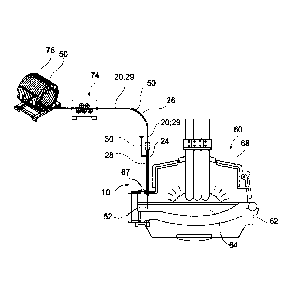
10 Figure 6 shows an electric arc furnace (EAF) 60 with an immersion device
10. The EAF
60 comprises a vessel 62 containing the metal melt 64, a movable lid 68 and a
platform
67 arranged on the side of the vessel 62. The entry point into the vessel 62
through
which the optical cored wire 50 enters the vessel 62 is arranged on the
platform 67.
The immersion device 10 is also arranged on the platform 67. Figure 6 shows
the
15 relative positions of the immersion device and the EAF in a merely
schematic manner.
However, the immersion device is typically configured to be fixed on the
platform 67,
such that the feeding tube 29, the blowing lance 28 and the leading end 52
remain
stationary when the vessel 62 is tilted during operation.
The optical cored wire 50 is arranged on a coil 76. It is moved, i.e. uncoiled
from the
coil 76 and wound back onto the coil 76, by a moving means 74. The moving
means 74
comprises rollers for moving the optical cored wire 50 and may include a servo
motor
to drive at least one of the rollers. Between the moving means 74 and the
blowing
lance 28, the optical cored wire 50 is guided inside the feeding channel 20.
The feeding
channel 20 has a bent portion 26 and straight portion 24 directed towards the
vessel
62. The feeding channel comprises a feeding tube 29 and a guiding channel
formed by
the central body of the immersion device 10. For the sake of clarity, the
detecting
means is not shown here.
Date Recue/Date Received 2022-01-26
2020P00150CA
16
List of Reference Signs
Immersion device 10
Feeding channel 20
First opening 21
Second opening 22
Straight portion 24
Location 25
Bent portion 26
Blowing lance 28
Feeding tube 29
Purge gas line 30
Space 32
Detector line 34
Gas flow 38
Flow divider 40
First line 41
Second line 42
De Laval nozzle 44
Optical cored wire 50
Leading end 52
Electric arc furnace 60
Vessel 62
Melt 64
Platform 67
Lid 68
Clamping device 70
Handle 71
Central body 72
Moving means 74
Coil 76
Date Recue/Date Received 2022-01-26