Note : Les descriptions sont présentées dans la langue officielle dans laquelle elles ont été soumises.
CA 03147117 2022-01-12
WO 2020/010411
PCT/AU2019/050739
1
BIN AID
TECHNICAL FIELD
[001] The invention relates to an aid for a bin or receptacle, and in
particular, the invention
relates to a device for use with a bin or other receptacle, the device being
adapted to
automatically raise and lower the lid of a bin or receptacle, or to provide
other conveniences.
BACKGROUND ART
[002] Bins and other receptacles may take a range of shapes and forms and
may be used
1.0 in a variety of contexts. They conventionally include a container body
and a lid or cover; the
lid or cover operates to protect or securely store the contents of the
container body. In the
context of rubbish bins, a lid or cover acts to prevent the escape of unwanted
odours or
rubbish from the container body, and also to deter the ingress of animals or
unwanted access
to the bin. The operation of a rubbish bin lid or cover is especially relevant
where a rubbish
bin is kept in a location accessible to the public at large.
[003] In some examples, bins or other receptacles are made to include an
automatically
opening or closing lid. In particular examples, the automatic lid of a bin may
be responsive to
motion at or near the location of the bin lid. In other examples, automatic
bin lids may operate
to sense objects located on the bin lid and then open the lid downward to
deposit the object
in the body of the bin. These examples relate to bin lids which are built into
the bin, or at least
an upper section of the bin, and do not act on an existing bin lid itself.
[004] In still other examples, a foot pedal may be included to mechanically
open a bin lid
in response to downward pressure applied to the pedal. These examples having
mechanical
operation are less convenient as they require the physical exertion of the
user, may be prone
to break down due to mechanical failure resulting from user interaction with
the mechanical
part, and may also be difficult to apply to existing bins or bin lids.
[005] Where a person has their hands full, particularly with the objects
they want to
deposit into a bin, they may find it difficult to open and/or close a bin lid
without having to
put the objects down. This may be inconvenient if there are a number of
different objects
CA 03147117 2022-01-12
WO 2020/010411
PCT/AU2019/050739
2
which could be time consuming to put down and pick up individually.
Furthermore, due to
disability, old age, physical impairments or other circumstances, some persons
may have
difficulty using, cleaning, managing or maintaining bins or other receptacles.
The difficulties
may be particularly apparent where the bin and/or bin lid is large, heavy
and/or difficult to
reach. Able bodied persons may also benefit from an aid that opens and closes
a bin lid to
coincide with the times they are depositing material into bins, or an aid
which provides for
other conveniences.
[006] A technical problem resides in creating a bin aid that is able to be
used with existing
bins, and which desirably has advantages of providing ease of access. For
example,
1.0 advantages provided may include providing a mechanism that operates
consistently to
automatically raise or lower the bin lid without damaging the bin or bin lid,
or that the bin lid
automatically opens when someone, or something, approaches the bin, or
advantages which
provides an increase in convenience. A technical problem also resides in
assisting with the
depositing of material into the bin by automatically opening the bin lid and
keeping the bin
lid open for such a time to permit depositing of material into the bin body,
thereby offering
increased convenience for the user. It is preferable for the bin lid to
automatically close after
objects have been deposited into the bin body. Other aspects of bin use,
including cleaning
and bin management (e.g. remembering which bin of many is the right one to be
placed on
the street on a given day), are recognised as being areas for improvement.
[007] Previous arrangements of the types described above are not entirely
satisfactory,
and there is accordingly a need to address one or more of the abovementioned
or other
limitations of the state of the art, or at least provide a useful alternative.
[008] It is to be understood that, if any prior art information is referred
to herein, such
reference does not constitute an admission that the information forms part of
the common
general knowledge in the art, in Australia or any other country.
SUMMARY OF INVENTION
[009] The present invention arises from a recognition that improvements in
relation to the
accessibility and convenience of bins or other receptacles can be achieved by
providing a
CA 03147117 2022-01-12
WO 2020/010411
PCT/AU2019/050739
3
device for use with a bin or other receptacle adapted to automatically raise
and lower the lid
of a bin or receptacle, or by providing other features to improve convenience.
[0010] According to one aspect of the invention, there is provided a bin aid
adapted to raise
and lower a bin lid of a bin, the bin aid including: a main body; a connection
means
functionally connectable with the main body and able to functionally engage
with the bin lid;
and a control means for controlling one or more functions to aid the use of a
bin including to
selectively control the at least one connection means; wherein the at least
one connection
means is able selectively to raise and to lower the bin lid with respect to
the closely located
bin.
1.0 [0011] According to a further aspect of the invention, there is
provided a bin aid adapted to
raise and lower a bin lid of a bin, the bin aid including: a main body; a
connection means
connected with the main body and able to functionally engage with, and to
functionally
disengage from, the bin lid; and a control means for selectively controlling
the at least one
connection means to selectively raise and lower the bin lid of the bin.
[0012] According to a further aspect of the invention, there is a provided a
bin aid adapted
to raise and lower a bin lid of a bin, the bin aid including: a connection
means able to
functionally engage with, and to functionally disengage from, the bin lid; and
a control means
for selectively controlling the at least one connection means to selectively
raise and lower the
bin lid.
[0013] Preferably, the connection means includes a rotatable unit.
[0014] Preferably, the connection means includes a bin lid engaging element.
[0015] The rotatable unit may include receiving means for receiving an
engaging element
for engaging with the bin lid. The receiving means is preferably able to lock
together with the
engaging element.
[0016] Preferably, the receiving means includes a jaw. The jaw preferably
includes a spring
loaded upper and/or lower portion, the upper or lower portion being movable to
open to
receive, and movable to close to lock together with, the engaging element.
[0017] Preferably, the engaging element includes a swing.
CA 03147117 2022-01-12
WO 2020/010411
PCT/AU2019/050739
4
[0018] The engaging element is preferably able to lock together with the
rotatable unit such
that the swing and rotatable unit move together when the rotatable unit moves.
[0019] The rotatable unit is preferably adapted to pull the swing downwardly.
[0020] Preferably, the rotatable unit and/or swing is able to translate. The
rotatable unit
and/or swing is preferably able to translate upwardly and/or downwardly.
Downward
translation of the rotatable unit and/or swing preferably enables raising the
bin lid, and
upward translation of the rotatable unit preferably enables lowering of the
bin lid.
[0021] Preferably, the rotatable unit and/or swing is able to translate
inwardly to and/or
outwardly from the bin. Inward translation of the rotatable unit and/or swing
occurs
lo preferably enables raising the bin lid and outward translation
preferably enables lowering the
bin lid.
[0022] Preferably, the swing is able to rotate and translate.
[0023] Preferably, the rotatable unit is able to rotate and translate the
swing.
[0024] Preferably, the rotatable element and/or swing is adapted to rotate
away from the
bin to enable raising the bin lid, and to rotate toward the bin to enable
closing the bin lid.
[0025] Preferably, the swing includes at least one portion having a shape that
is
complementary to the shape of the receiving means of the rotatable element.
The at least
one complementary shaped portion of the swing may have a non-circular cross
section. The
at least one complementary shaped portion may include at least three planar
faces.
Preferably, the at least one complementary shaped portion has a rectangular
cross-section.
[0026] Preferably, the at least one complementary shaped portion of the swing
comprises
a middle portion of the swing. The at least one complementary shaped portion
of the swing
may comprise a bar.
[0027] The engaging element is preferably adapted to raise or lower the bin
lid by applying
a force to the underside of the bin lid. Preferably, the force is able to be
applied by pivoting
the engaging element upon the bin. Preferably, pivoting of the engaging
element occurs as
the swing moves. Preferably, the pivoting is upon a handle of the bin.
[0028] In a preferred form, the engaging element includes at least one lifter
for engaging
with the underside of the bin lid.
CA 03147117 2022-01-12
WO 2020/010411
PCT/AU2019/050739
[0029] Preferably, the engaging element is able to engage with a first
underside section of
the bin lid, and a second opposing underside section of the bin lid on the
other side of the lid.
[0030] The engaging element preferably includes one or more arms that extend
outwardly
from the swing. Preferably, the arms extend inwardly towards the bin when in
situ.
5 [0031] Preferably, the at least one lifter is locatable at the end of
each arm.
[0032] Each at least one lifter preferably includes a lifting element for
engaging the
underside surface of the bin lid. Preferably, the lifting element is able to
rest on the upper
surface of a rim of the bin when the bin lid is in a closed position.
[0033] Preferably, the lifting element includes a planar section. The lifting
element may
io include a winged section. Preferably, the winged section is adapted to
engage with increased
surface area of the lower surface of the bin lid.
[0034] Preferably, each at least one lifter is removably connectable to end of
each arm.
[0035] Preferably, each at least one lifter includes a shaped part to pivot on
a bin handle.
The shaped part is preferably shaped to have a complementary fit with an
exterior surface of
the bin handle. In a preferred form, the shaped part is semicircular or 'U'
shaped.
[0036] Preferably, the engaging element is adapted to extend across a width of
the bin lid.
The engaging element may be adapted to have an adjustable width. In a
preferred form, the
engaging element is adjustable in width to fit bins having different widths.
Preferably, the
middle portion of the swing and/or the arms are adjustable in length to adjust
the width of
the engaging element.
[0037] The connection means preferably includes a translation element for
moving the
rotatable unit. Preferably, the translation element is cyclically moveable.
The translation
element is preferably connectable to the rotatable unit. The translation
element may
comprise a shaft. The rotatable unit is preferably rotatable with respect to
the shaft.
[0038] Preferably, the translation element is engageable with a drive unit to
translate the
shaft upwardly and downwardly. Preferably, the drive unit is able to translate
the shaft
downwardly or upwardly in a cyclical manner to selectively raise or lower the
bin lid. The shaft
includes may include a rack for interacting with a pinion in the drive unit.
CA 03147117 2022-01-12
WO 2020/010411
PCT/AU2019/050739
6
[0039] The translation element may comprise a chain including a plurality of
chain
elements. Preferably, chain elements in the chain are able to be translated
downwardly or
upwardly for selectively raising or lowering the bin lid.
[0040] In a preferred form, the rotatable unit includes direct receiving means
for directly
receiving the bin lid. Preferably, the direct receiving means is able to lock
together with the
bin lid. Preferably, the direct receiving means is able to lock together with
bin lid such that
the bin lid and direct receiving means move together when the direct receiving
means moves.
Preferably, the direct receiving means is able to receive and lock together
with a rearward
portion of the bin lid. Preferably, the direct receiving means is able to push
the rearward
lo portion of the bin lid downwardly to provide for raising of an opposing
frontward portion of
the bin lid.
[0041] The direct receiving means is preferably adapted to rotate and
translate. In a
preferred form, the direct receiving means is adapted to rotate and translate
the rearward
portion of the bin lid
[0042] Preferably, the connection means includes a pivot means. Preferably,
the pivot
means is connectable to the rotatable unit. Preferably, the pivot means is
able to move the
rotatable unit upwardly and/or downwardly. Preferably the pivot means is able
to move the
rotatable unit inwardly to and outwardly from the main body.
[0043] Preferably, the pivot means is able to rotate relative to the main
body.
[0044] Preferably, the pivot means includes a shaft connectable to the
rotatable unit that is
movable upwardly and/or downwardly.
[0045] Preferably, the control means controls the rotating of the rotatable
unit and/or the
translating of the translation element and/or the pivoting of the pivot means.
[0046] Preferably, the control means includes one or more electronic control
functions
operative to move, rotate and/or translate the connections means, or a part
thereof.
[0047] Preferably, the bin aid is adapted to aid the use of a closely located
bin.
[0048] According to a further aspect of the invention, there is provided a bin
aid adapted to
aid the use of a closely located bin including to raise and lower a bin lid of
the bin, the bin aid
including: a main body; at least one connection means functionally connected
with the main
CA 03147117 2022-01-12
WO 2020/010411
PCT/AU2019/050739
7
body and able to functionally engage with a bin lid of a closely located bin;
a control means
for controlling a plurality of functions to aid the use of a bin including one
function to
selectively control the at least one connection means; wherein the at least
one connection
means is able selectively to raise and to lower the bin lid with respect to
the closely located
bin.
[0049] Preferably, the connection means includes an arm and one or more
electronic
control functions operative to raise or lower the arm.
[0050] The arm may be able to be placed into an engaged position with respect
to the bin
lid of a closely located bin, and a non-engaged position with respect to the
bin lid, wherein
io when the arm in the engaged position is raised, the bin lid is raised,
and when the arm in the
engaged position is lowered, the bin lid is lowered
[0051] The connection means may include a cable and one or more electronic
control
functions operate to extend or retract the cable.
[0052] Preferably, the arm is able to be placed into an engaged position with
respect to the
bin lid of a closely located bin, and a non-engaged position with respect to
the bin lid, wherein
when the cable in the engaged position is retracted, the bin lid is raised,
and when the cable
in the engaged position is extended, the bin lid is lowered.
[0053] The connection means may include an engaging element for engaging the
lid of the
bin.
[0054] The engaging element for engaging the lid of the bin may be a plate or
arm for
engaging an under-surface of the bin lid or bin handle.
[0055] The engaging element for engaging the lid of the bin is preferably a
magnetic
connector for engaging a metallic or magnet connected to the bin lid or bin
handle.
[0056] According to a further aspect of the invention, there is provided a bin
aid adapted to
raise and lower a bin lid, the bin aid including: an arm moveably attached to
main body, the
arm being able to be raised and lowered with respect to the main body; one or
more
electronic control functions to operate the raising or lowering of the arm;
the arm being able
to be put into an engaged position with respect to the bin lid, and a non-
engaged position
CA 03147117 2022-01-12
WO 2020/010411
PCT/AU2019/050739
8
with respect to the bin lid; wherein when the arm in the engaged position is
raised the bin lid
is raised, and when the arm in the engaged position is lowered, the bin lid is
lowered.
[0057] According to an aspect of the invention, there is provided a bin aid
adapted to raise
and lower a plurality of bin lids, the bin aid including: a plurality of arms
movably attached to
a main body, the arms being able to be raised and lowered with respect to the
main body;
one or more electronic control functions to operate the raising or lowering of
the plurality of
arms; each arm is able to be put into an engaged position with respect to one
of the bin lids,
and a non-engaged position with respect to one of the bin lids; wherein when
one of the arms
is raised in the engaged position one of the bin lids is raised, and when one
of the arms is
1.0 lowered in the engaged position one of the bin lids is lowered.
[0058] The bin aid is separable from the bin and bin lid. The bin aid is
preferably adapted to
engage with a bin including one or more wheels, and said bin is preferably
able to be wheeled
away from the bin aid when the arm is in a non-engaged position with respect
to the bin lid
of said bin.
[0059] The bin aid is able to be retrofit to an existing bin and bin lid.
[0060] The bin aid may include at least two arms, and the main body may be
centrally
located such that one or more first side arms are movably attached to a first
side of the main
body, and one or more second side arms are movably attached to a second side
of the main
body, the second side being on the opposite side to the first side of the
central main body.
[0061] Each arm attached to the main body is preferably adapted to engage with
a bin lid
via engagement means. The engagement means may be located towards an end of
the arm.
[0062] The bin lid engagement means may include a magnet on an arm for
magnetically
engaging with a magnet attachable to a bin lid.
[0063] The magnet may be mounted on the arm. The magnet is preferably
attachable to the
bin lid by screwing the magnet into the bin lid.
[0064] The magnet on the arm may be tethered to the arm.
[0065] The bin lid engagement means may comprise a strip of material movable
through a
handle of the bin lid, the strip including a magnetic portion.
CA 03147117 2022-01-12
WO 2020/010411
PCT/AU2019/050739
9
[0066] The bin lid engagement means may comprise a hook which is adapted to
engage with
a handle located on the upper surface of the bid lid.
[0067] The bin lid engagement means may comprise a push down locking member.
The push
down locking member may include a movable latch. The latch may comprise a
movable jaw.
The push down locking member may engage with the bin lid by receiving a
downward force
to move the movable latch or jaw inwards.
[0068] The arm may be extendable in length.
[0069] The bin aid may include a bin container engaging means. The bin
container engaging
means preferably engages with a rear portion of the bin container. The bin lid
engagement
1.0 means and the bin container engagement means may co-operatively engage
with the bin.
[0070] Preferably, the bin aid includes a sensing means for sensing when the
bin is a suitable
location for the bin lid engagement means to engage with the bin lid. The
sensing means is
preferably able to sense when a bin engages with the bin container engaging
means. The
sensing means is preferably able to sense whether or not a bin lid engages
with the bin lid
engaging means (i.e.. whether the arm is in the engaged or a disengaged
position with respect
to the bind lid).
[0071] The arm may be movable to a bin insertion position in which the arm is
raised with
respect to the main body. Preferably, the arm permits insertion of the bin
into the bin
container engaging means when the arm is in the bin insertion position.
[0072] The arm preferably moves automatically to the bin insertion position
where the bin
is not sensed by the bin sensing means and/or the bin lid engaging means
sensor senses that
the arm is in a disengaged position.
[0073] There may be a delay between automatically moving the arm into the bin
insertion
position after the arm is placed in a disengaged position.
[0074] A sound may be generated by the bin aid when the arms are raised or
lowered. The
sound may be generated where the arm is automatically raised after being
placed in a
disengaged position.
[0075] The arm may be placed in the engaged position when:
CA 03147117 2022-01-12
WO 2020/010411
PCT/AU2019/050739
- the sensing means senses that the bin engages with the bin container
engaging means;
and
- the sensing means senses that the bin is in a suitable location for the
bin lid engagement
means to engage with the bin lid; or
5 - the bin has been inserted into the bin container engaging means.
[0076] The arm(s) may be placed in the disengaged position after they are in
the engaged
position.
[0077] Preferably the one or more electronic control functions include any one
or
combination of the following:
1.0 - A remote control to operate the arm(s) remotely from the bin aid
- A motion sensor to operate the arm(s) in response to motion detected by
sensor
- A foot switch to operate the arm(s) when a switch is activated by the
foot of a user
- An override function which, when activated, maintains the arm(s) in
either a raised or
lowered state
[0078] The bin aid may be free standing and include a base and intermediate
section located
between the main body and the base.
[0079] Preferably, the base includes a fillable chamber. The fillable chamber
may be filled
with sand, water, or other granular or fluid substances.
[0080] The bin aid may be adapted to be fixed to a separate structure to
locate the arm(s)
at a sufficient height above the bin lid(s), and to be at a sufficient
distance from said separate
structure, to enable the arm(s) of the bin aid to raise and lower the bin
lid(s).
[0081] In a preferred form of the invention, at least one of the arm(s) is
supported by one
or more auxiliary base(s) which are spaced apart from each other and the base.
[0082] At least one of the arm(s) may be supported by one or more brackets
adapted to be
fixed to a separate structure. The separate structure may be the same
structure to which the
bin aid is adapted to be fixed.
CA 03147117 2022-01-12
WO 2020/010411
PCT/AU2019/050739
11
[0083] Each arm is movable with respect to the main body between a raised
position and a
lowered position.
[0084] The main body may include a plurality of rotating bosses on each of the
left and right
sides of the main body, each rotating boss being attachable to a base of an
arm, and able to
raise and lower the arm by rotating with respect to the main body. The
plurality of rotating
bosses are preferably vertically spaced to permit locating an arm on a higher
boss or a lower
boss, according to height of the bin and bin lid which the arm is intended to
raise and lower
[0085] The arm(s) may be raised and lowered by an electric motor located in
the main body.
The electric motor is powered by a battery which is located in the main body,
or elsewhere in
or on the bin aid. The battery may be charged by a mains connection and/or
solar panel. The
solar panel may be located on a pole which extends from the main body.
[0086] The main body may include a battery charge display to indicate the
amount of charge
remains in the battery.
[0087] The arm(s) may be raised and lowered by an electric motor powered by a
mains
connection.
[0088] The main body may include a photocell for responding to ambient light.
[0089] The main body may include a temperature display
[0090] The bin aid may include a bin aid light to illuminate an area around
the bin aid. When
the light intensity is below a pre-determined threshold, the bin aid light may
automatically
turns on; and when the light intensity is above a pre-determined threshold,
the bin aid light
may automatically turns of
- The bin aid may include a bin light for illuminating the inside of a bin.
- The bin aid may include a washer jet for spraying a liquid into a bin.
[0091] The liquid is preferably de-odourising. The liquid may have animal or
insect deterring
properties. The liquid may be stored in a refillable tank. Preferably, the
refillable tank is
located on the main body. The refillable tank preferably includes a liquid
sensor to indicate
when the liquid in the tank is low. The liquid sensor is electronically
connected to an indicator
able to indicate when the liquid in the tank is low.
CA 03147117 2022-01-12
WO 2020/010411
PCT/AU2019/050739
12
[0092] When the bin lid engaging means is engaged, and the bin lid is raised,
the bin aid is
able to spray liquid into the bin via a liquid jet.
[0093] The bin aid is preferably electronically connected to an indicator able
to indicate one
or more of the following:
- battery charge
- amount of liquid in the tank
- whether it is 'bin night'
[0094] The main body preferably includes a plurality of buttons, the plurality
of buttons
controlling one or more of the following actions:
1.0 - turning the LED lights on or off
- keeping a lid open for a set time
- turning a sensor on or off
- turning power on or off
[0095] The features described in relation to one or more aspects of the
invention are to be
understood as applicable to other aspects of the invention.
Advantageous effects of invention
[0096] Many advantages are achieved by the present invention, many of which
will be well
appreciated by a skilled person.
BRIEF DESCRIPTION OF DRAWINGS
[0097] Notwithstanding any other forms which may fall within the scope of the
present
invention, preferred embodiments of the invention will now be described, by
way of example
only, with reference to the accompanying drawings in which:
[0098] FIG 1 is a schematic drawing of a wheelie bin for use with a bin aid
according to
preferred embodiments of the present invention.
CA 03147117 2022-01-12
WO 2020/010411
PCT/AU2019/050739
13
[0099] FIGS 2 to 4 are schematic side views of a bin aid fixed to a separate
structure
according to four different preferred embodiments of the present invention.
[00100] FIG 6 is a schematic front view of a multi-station bin aid for use
with two wheelie
bins of different sizes according to a further preferred embodiment of the
present invention.
[00101] FIG 7 is a diagrammatic flow diagram of the interactive use of a bin
aid and a closely
located wheelie bin according to a preferred embodiment of the present
invention
[00102] FIGS 8 to 12 are d schematic side views of a bin aid interaction to a
bin lid of a closely
located wheelie bin according to four different preferred embodiments of the
present
invention.
lo [00103] FIG 13 is a schematic view of a control and communication system
of a bin aid
according to a preferred embodiment of the present invention.
[00104] FIGS 14, 15 and 16 are schematic front view, side view and top view of
a first example
of a bin aid according to a particularly preferred embodiment of the
invention.
[00105] FIGS 17A, 1713 and 18 are schematic side views and top view of a
second example of
a bin aid according to a particularly preferred embodiment of the invention.
[00106] FIGS 19, 20 and 21 are schematic front view, side view and top view of
a third
example of a bin engaging element of a bin aid according to a particularly
preferred
embodiment of the invention.
[00107] FIG 22 is a schematic top view of a fourth example of a bin engaging
element of a bin
aid example.
[00108] FIG 23 is a schematic side view of an embodiment of a rotatable unit
and connected
translation element
[00109] FIG 24 is a schematic side view of a second embodiment of a rotatable
unit and
connected translation element.
[00110] FIG 25 is a schematic side view of a third embodiment of rotatable
unit and
connected translation element.
[00111] FIGS 26 to 29 are a schematic side and perspective views of a fourth
embodiment of
rotatable unit and connected translation element.
CA 03147117 2022-01-12
WO 2020/010411
PCT/AU2019/050739
14
[00112] FIGS 30 to 32 are a schematic side and perspective views of a fifth
embodiment of
rotatable unit and connected translation element.
DESCRIPTION OF EMBODIMENTS
[00113] A range of embodiments of a bin aid is shown by the Figures and is as
described and
depicted herein in connection with an illustrative but series of non-limiting
preferred
embodiments for a particular application.
As shown in Figure 1 a bin for use with the bin aid of the invention, is
commonly known as a
"wheelie bin" 15 and comprises a base container 16 having a receiving internal
volume and
1.0 shaped with a generally quadrilateral vertical cross-sectional shape.
The volume is primarily
expanding horizontal rectangular shape from a smaller base to a wider open
mouth top
covered by a hinged closing lid 17. The hinge 21 supporting the hinged lid 17
is at a back top
edge and from which extends in the opposite direction a handle 22. At the
bottom corner
beneath the handle 22 is a pair of wheels 20 on a single axle, which the bin
15 can pivot on
by tugging the handle 22 and allowing the bin to be rolled into required
position. Hence the
derivation of the term "wheelie bin".
[00114] The structure, principle and operation of the described aid, as will
be appreciated by
those skilled in the art includes a structure adapted to aid the use of a
closely located wheelie
bin 15 including to raise and lower a bin lid 17 of the bin, the bin aid
including: a main body;
at least one connection means functionally connected with the main body 30 and
able to
functionally engage with a bin lid 17 of a closely located bin; a control
means for controlling
a plurality of functions to aid the use of a bin including one function to
selectively control the
at least one connection means; wherein the at least one connection means is
able selectively
to raise and to lower the bin lid with respect to the closely located bin.
[00115] The main body 30 of the bin aid can comprise various forms. In one
form as shown
in Figure 2 the main body 31 is a fixed body which allows a wheelie bin 15 to
be wheeled onto.
This becomes a wheelie bin station.
[00116] In another form as shown by Figure 3, the main body can be a wheeled
main body
32 and itself can have a supporting wheel 33 separate to the wheelie bin wheel
20 and
CA 03147117 2022-01-12
WO 2020/010411
PCT/AU2019/050739
therefore allow movement of the wheelie bin station to a required position and
then locate
the wheelie bin 15 in a closely located position.
[00117] Referring to Figure 4 the main body 34 can be integral with the
wheelie bin 15 and
therefore be transported on the wheels 20 of the wheelie bin.
5 [00118] A still further embodiment of the main body 31 that stands as a
fixed wheelie bin
station but can include a supporting wheel 36 which does not come into play
until the wheelie
bin station is tilted a certain amount. In this way the main body 35 forms a
stable base until
it has been suitably tilted to the moving wheeled position and form a wheeled
main body 32.
[00119] Referring to Figure 6 there is a multi-station 37 able to coordinate
with two bins 15
io and 15X that can be different sizes. Often there is a tendency by
Councils to encourage
particular waste distribution rules. Therefore, the landfill general waste bin
can be a smaller
bin to the green waste or recyclable bin so as to encourage composting and
recycling. The
main body 37 is able to cater for either size. There can be adjustable of such
a unit to allow
multi-station use of two same sized bins whether large or small.
15 [00120] The main body 30 in its various forms can include a stabilising
base 52. This can be
a larger footprint base or a weight increase base so as to bring the centre of
gravity of the bin
aid to a substantially lower position and prevent accidental tipping. Such
weight increase of
base can be a water or sand filled base container or it can include a solid
heavy base.
[00121] Referring to Figures 8 to 12 there are examples of a bin aid
interaction to a bin lid of
a closely located wheelie bin. In particular, an important interaction is the
automatic raising
of the lid 17 of the bin 15 by the arm 40 of the bin aid 30. The arm 40 can
take various forms
including those shown.
[00122] In Fig 8 the arm 41 is pivotally attached to the main body 30 of the
bin aid and can
be driven by a drive motor in a circular manner around the pivot hinge of the
arm 41. The
arm 41 can extend between the lid 17 and body 16 of the bin 15 and therefore
lift the lid 17
from underneath.
[00123] In Fig. 9 the arm 42 is again pivotally hinged to the main body 30 of
the bin aid but
the arm extends around the side so as to engage under the lid 17 at a distance
from the
hinging of the lid 17 to the body 16. This arm can extend across the body 16
of the bin and
CA 03147117 2022-01-12
WO 2020/010411
PCT/AU2019/050739
16
engage with a similar arm extending from the main body on the other side of
the bin. In this
way sideways distortion is avoided. Still further the arm 42 can have a crank
shape so that
the crank provides a strengthening portion at the far extremity of the arm 42
from the hinged
connection to the main body.
[00124] In Fig 10 the arm 43 is hingedly connected to the main body and driven
by a rotating
motor. However, in this form the arm 43 extends over the top of the lid 17 and
is connected
to the lid. This can be done by detachable means such as a magnet at the end
of the arm 43
that interacts with a complementary magnet 44 or steel plate mounted on the
bin lid 17. In
this way the lid 17 is lifted from above. This system can use a reel instead
of a hinged arm at
1.0 the connection with the main body such that letting out and retracting
a flexible line
connected to the magnet 44 will result in controlled opening and closing of
the lid 17.
[00125] Figure 11 shows an arm 45 that interacts and engages the handle 18 on
top of the lid
of the bin.
[00126] Figure 12 shows a rotatable unit 46 including a jaw for directly
receiving the bin lid
that can be mounted and can move a swing 85 attached to the handle 22 (as
described later)
or a rearward portion 19 extending rearwardly of the bin lid 17 on the other
side of the bin
lid pivot 21. Also depicted in Fig 12 is translation element (or arm) 48 which
can translate
upwardly and downwardly, and which connects to the rotation means 49 for
rotating the
rotatable unit relative to the translation element 48. The translation element
48 is extendable
(not shown) and is also connected to the pivot means 47 which permits pivoting
of the
translation element relative to the body 30. As will be understood by the
person skilled in the
art, the rotatable unit 30 is selectively controllable by the controller (not
shown) to move
downwardly via pivot means 47 and, as a result of the extension of the length
of the
translation element (also not shown), away from the post 30, to raise the bin
lid; and the
rotatable unit 30 is able to move upwardly and, as a result of a reduction in
the length of the
translation element, towards the post 30, to close the bin lid. The rotation
means 49 and
pivoting means 47 comprise electrically controlled gears and pinions situated
on the rotatable
element and the post (not show). Alternatively, the rotation or pivoting means
may comprise
other mechanisms or components known to the skilled addressee.
CA 03147117 2022-01-12
WO 2020/010411
PCT/AU2019/050739
17
[00127] Opening Means ¨ Preferably opening means will be automatic so as to
allow hands
free operation off the opening of the lid 17 of the bin 16 when the user's
hands are full with
rubbish to be placed into the bin.
[00128] 1-Where there are multiple bins, each will have a control unit that it
will be attached
to. There will be one master control unit with all of the controls in it, for
each house to control
their rubbish bin, there are too many houses that has only one bin so those
houses only needs
a master unit. If the house or premises has more than one bin, therefore will
need one master
unit and a unit that the bin will be attached to but this unit will do
whatever the master unit
tells it to do. the master unit will be dominant to the slave unit. They will
look the same but
1.0 operate differently. There can be hard wiring that will go from master
unit to the slave units
to be able to control them. However, in another form there can be electronic
connection like
Wi-Fi or Bluetooth.
2- The bin attachments can interlock with the master and slave units. In this
way you can
have multiple bins or be in an apartment with multiple bin users and other
options.
3- options can include the ability to remove the bins from the units or vice
versa so that not
only is there retrofitting possible but reversal of the retrofitting. This is
often important when
users move locations and the bin remains council property and is retained on
the existing
property.
[00129] A- Remote control - A user's foot can enable opening of the lids by
engaging the right
slipper and the user's left foot can release the bin from the main unit for 10
minutes. If the
bin is not removed, it will lock again. If it is your day to take the bins
out, and you are inside
the house, with the rubbish and recycle bags in your hand you just have to
step on the right
slipper to open the lids and left slipper to release the bins so after you put
the trash in the
bins and the bins are closed, then you can pull the bins out from the units.
[00130] B- Wi-fi connection - when a user comes home from work, normally they
want to
take the bins out so when they go inside the house, they don't want to come
out again. There
is provided an application on a personal electronic device so that the use can
connect to the
bins through their wi-fi and release the bins from the master unit or the
slave units and
whichever they don't remove will lock again after 10 minutes or it will be
adjustable so a
suited time is programmed.
CA 03147117 2022-01-12
WO 2020/010411
PCT/AU2019/050739
18
EXAMPLE 1
[00131] Referring to Figs 13 to 16 there is shown a bin aid with a main body
30 in its various
forms can include a stabilising base 52. This can be a larger footprint base
or a weight
increase base so as to bring the centre of gravity of the bin aid to a
substantially lower position
and prevent accidental tipping.
[00132] The main body includes a leg portion 51 mounted on the stabilising
base 52 and
supporting a middle-elongated section 53 and a colinear top extension portion
54 supporting
a solar panel 55. The bin aid is elongated and upright so as to coextend next
to a bin. It can
operate without a separate supporting main body 30 as that function is built
in particularly
1.0 with the supporting base 52.
[00133] Connected to and on either side of the main middle elongated section
53 are two
arms 42 that are at different heights so as to overly different height bins
such as shown in Fig
6. The arms tip where will land on the bins and have a set of strong magnets
61 and where
they land the lids will have a round big headed self-tapped screw. The
consumer just screws
the self-tapped screws into the bins. The attachable magnets will be able to
be screwed to
the end of the arms which will land on the lid when the arms go down.
[00134] As shown in Fig 15 there is located on top and bottom of the body some
night lights
69. The bin aid can have an optional night light which will work with the
photocell sensor 67.
It will go on when its dark and off with sunrise. It will operate with on and
off switch as
required. Useful for very dark areas.
[00135] Further the bin aids can include a deodorant + washer unit 60 built
into the body 53
and having a specialised 2 litre liquid chamber, which will hold chemicals
that will make
deodorise the bins, improve smell and keep the flies and birds away. This
liquid will last about
6 months. The body has two water jets 68 on either side of an LED spot light
and below a
water temperature gauge 61 that monitors washing liquid temperature.
[00136] Referring to Fig 14 there are controls on the front of the main body.
This includes
switches comprising of:
- Water tank empty indicator 62
- LED lights on/off 63
CA 03147117 2022-01-12
WO 2020/010411
PCT/AU2019/050739
19
- Lid open on/off 64
- Sensor on/off 65
- Main power on/off key 66
[00137] It can be seen that this version of bin aid is self-sufficient and a
standalone product.
It includes solar panel so as to be self-powering and apart from rare filling
of the water tank
can stay operational for months without maintenance or resetting. It is this
continual action
for a continual daily problem of bins that provides one substantial advantage
to the users.
EXAMPLE 2
[00138] Referring to Figs 17A, 178 and 18 there is shown a body 30 including
optional
io controls on the side of the main body. This allows the front of the main
body to be away from
the optional controls and therefore the water jets are away from the controls.
This lessens
the need for waterproofing electronics beyond splash protection. It also
allows for front latch
means comprising a jaw 77 for bin attachments to be mounted and a rubber slot
78 for the
latch slide groove to allow the latch means (jaw) to move up and down.
[00139] The body 30 includes mounting means 90 for mounting the connection
means to the
body. The connection means comprises rotatable unit 77, translation element
comprising
shaft 92, drive unit which in the present embodiment comprises the pinion 91
and spring
means 94, and a bin lid engaging element (not shown). The drive unit further
operates to
translate the shaft of translation element 92 and enable pivoting of the shaft
of the translation
element with respect to the body 30.
[00140] The pinion 91 comprises a circular gear adapted to engage with linear
gear on the
rearward side of the drive shaft 92. The pinion is able to be selectively
controlled by the
control means to rotate the pinion in a clockwise direction to translate the
shaft 92
downwards, and to rotate to pinion in a counter-clockwise direction to
translate the shaft 92
upwards with respect to the body. When the rotatable unit 77 is functionally
connected to a
bin lid (e.g. by bin lid engaging element, not shown) it is able to raise and
lower the bin lid.
[00141] In more detail, the upper jaw 95 moves upwardly away from the lower
jaw 96 to
receive the swing of the bin lid engaging element (not shown). Once the swing
has been
received, the upper jaw 95, due to a spring loaded bias, then moves towards
the lower jaw
CA 03147117 2022-01-12
WO 2020/010411
PCT/AU2019/050739
96 to lock the swing together with the receiving means (i.e. the upper and
lower jaws, 95, 96)
of the rotatable unit 77.
[00142] Once the rotatable unit 77 has received the swing, the pinion may be
selectively
controlled to rotate in a clockwise direction to lower the shaft 92. As the
shaft 92 is lowered,
5 it brings the swing downwardly. As the swing moves downwardly, it
together with the
rotatable unit 77, rotate relative to the shaft 92. Additionally, as the swing
moves
downwardly, it will also move (together with the shaft 92 and rotatable unit
77) outwardly
from the body 30 and inwardly toward the bin (not shown). This movement of the
shaft and
rotatable unit is permitted by spring means 94 that includes roller which
rolls along the shaft
1.0 and provides spring loaded resistance in a horizontal direction against
the translation element
in operation. The spring means is able to contract (see Fig 1713) to permit
the shaft 92 to pivot
(or rotate) with respect to the body 30 when the rotatable unit/swing has
completed its
translation and rotation as depicted in Fig 176 and has raised the bin lid
(not shown). It will
be appreciated that the rotatable unit can rotate relative to the shaft by jaw
holder 97 which
15 holds the upper and lower jaws 95, 96, since the jaw holder is pivotably
connected to the
housing 93 that is attached to the shaft 92. In Fig 1713 the jaw holder and
jaws 95, 96 are at
an acute angle relative to the shaft such that the jaws 95, 96 can pull down
the swing.
[00143] The pinion may be also be selectively controlled to rotate in a
counter-clockwise
direction to translate the shaft 92 upwardly. As the shaft 92 is moved
upwardly relative to the
20 body 30, it translates the swing upwardly. As the swing moves upwardly,
it together with the
rotatable unit 77, rotates relative to the shaft 92. Additionally, as the
swing moves upwardly,
it will also move (together with the shaft 92 and rotatable unit 77) inwardly
to the body 30
and outwardly from the bin (not shown). This movement of the shaft and
rotatable unit is
permitted by spring means 94 that includes a roller which rolls along the
shaft and provides
spring loaded resistance in a horizontal direction against the translation
element in operation.
The spring means is able to expand (see Fig 17A) when the shaft 92 to pivots
(or rotates)
towards a vertical orientation when the rotatable unit/swing moves towards its
initial position
as depicted in Fig 17A. In this initial position it will be understood that
the connection means
5 may be functionally connected or disconnected from the bin (not shown) by
the
engagement or disengagement of the receiving means (i.e. movable jaws 95, 96)
with the
CA 03147117 2022-01-12
WO 2020/010411
PCT/AU2019/050739
21
swing. In Fig 17A the jaw holder 97 and jaws 95, 96 are approximately
perpendicular relative
to the shaft 92.
[00144] The weight of the bin 15 keeps the body of the bin 16 relatively
stable and in the one
location. However, stabilising means (not shown) can be provided to receive
the wheels 20
or another part of the bin to further stabilise the bin 15 as the connection
means is controlled
to raise and lower the bin lid 17.
[00145] The side controls include switches comprising of:
- LED lights on/off 71
- Lid open on/off 72
- Sensor on/off 73
- Shock sensor on/off 74
- Main power on/off key 75
[00146] As shown in Fig 18 there is located on top and bottom of the body some
night lights
70. The bin aid can have an optional night light which will work with the
photocell sensor 73.
It will go on when its dark and off with sunrise. It will operate with on and
off switch as
required. Useful for very dark areas.
[00147] Further the bin aids can include a deodorant + washer unit built into
the body and
having a specialised 2 litre liquid chamber, which will hold chemicals that
will make deodorise
the bins, improve smell and keep the flies and birds away. This liquid will
last about 6 months.
The body has two water jets 76 on either side of an LED spot light 80 and
below a water
temperature gauge 71 that monitors washing liquid temperature.
[00148] Pre-set time 3 am (the time will be locked into a convenient non-use
time). When
the bins are emptied and put back in position the bin lids will open overnight
at 3 am by the
timer and spray the deodorant into each bin for 2 seconds. First one bin then
the other, then
close the lid, if the bin is not in the position will not spray. The user will
activate the function
with the switch as required. The red light will stay on with the EMPTY
writing, as the water is
low in the tank. The motor will not work if the tank is empty.
EXAMPLE 3
CA 03147117 2022-01-12
WO 2020/010411
PCT/AU2019/050739
22
[00149] Referring to Figs 19 to 21, the bin lids attachments or bin lid
engaging elements can
in one embodiment for a household bin include a number of pieces. It can be
adjusted to fit
the bin, - whether it is small or big. The parts of the attachments include a
swing 85 with arms
86, two lifters 82, and securing means to secure the swing to the lifters
(e.g. using two Locks
89). It should be noted that the bin lid 17 is depicted in Fig 20 and 21 but
is not depicted in
Fig 19.
[00150] The swing 85 has a functionally significant role for the automated bin
opener
embodiment depicted in Figures 19 to 21. The swing 85 is a bar that in use
extends across
the width of the bin 16 and ends in two arms 86 that protrude inwardly towards
the bin. The
1.0 bar portion of the swing can angle outwardly from the bin but has a
central rectangular or
non-circular cross section central bar portion 88. This non-circular cross
section allows for
ready gripping by a rotating means. The width of the bin engaging element may
be extended
or reduced by adjusting the length of the arms 86 which have the ability to
recede into
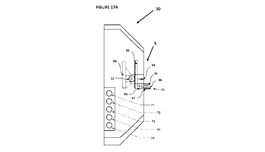
recesses in the swing 85 (not shown). Alternatively, the arms 86 may include
telescoping
.. parts, or other components known to the skilled addressee to permit the
adjusting of their
length.
[00151] The swing 85 is held in position by lifters 82 that provide for the
positioning of the
swing and the lifting of the bin lid.
[00152] The positioning of the swing 85 is achieved by the lifter 82 having
two shaped
connected parts 82A, 826. At one end is an inverted U shaped part 82A with one
longer arm
that fits over the bin handle 22 and has the longer arm extending below the
handle 22. The
other shaped part 826 at the other end, called a lifting element, is a flat
plate section that
extends rectilinearly from the inverted U-shaped part 82A so as to reach and
to overly the rim
of the bin 16.
[00153] The length of the swing 85 will be adjustable laterally to change
according to the bin
width size. The lifters 82 length and height will vary according to bin shape.
[00154] There are two holes 83, 84 on each lifter 82 ¨ one hole 84 is in the
one longer arm of
the inverted U shape of the lifter. This hole on the front is for the arm 86
of the swing 85 to
extend therethrough and underneath the handle so as to encapsulate the handle
while still
allowing the swing 85 to rotate around the handle 22. The other hole 83 is on
the flat portion
CA 03147117 2022-01-12
WO 2020/010411
PCT/AU2019/050739
23
of the lifter 82 and in position is between the handle and the rim of the bin
for receiving the
shackle of the locks 89.
[00155] There is one hole 87 on each end of the arms 86 of the Swing 85. When
the Swing
85 engages with the lifters during installation, the arms 86 extend through
the hole 84 of the
curved portion of the lifter 82 and the hole in the end of the arm 86 is
pushed in until it
underfits and aligns with the holes 83 on the flat portion of the lifter
attached to the top of
the bin 16. This is locked in position by the locks 89.
[00156] The swing 85 and the holes on the lifters 82 will line up so the
consumer can attach
the locks 89 to secure them onto the bins 16. There are two locks for every
bin and both locks
1.0 can have the same key but different set of keys from other bins. The
locks will engage with
the Swing and the lifter to hold them together.
[00157] It can be seen that after fulfilling this clean retrofit the lid 17
can readily rotate and
overly the flat part of the lifters 82 that overly the rim of the bin 16A.
Every bin, no matter
what size and height, will have 2 lifters 82 at either end of the bin handle
22. The left lifter
will sit on the left side of the bin handle and underneath the left, back
corner of the lid. The
right lifter will sit on the right side of the bin handle and underneath the
right, back corner of
the lid.
[00158] As shown diagrammatically in Figs 17A, 1713 and 19 to 21, the way the
lifters 82 will
work, when the central part of the swing 88 is pushed down by the main unit,
the lifting
element 828, overlying the rim of the bin 16A and underlying the lid, will
rise up and will lift
the bin lids upward. In particular, the winged section of the lifting element
828 pushes against
a part of the hinge of the bin lid 17, which hinged part of the bin lid 17 is
robust and resistant
to the forces exerted on it by the winged section of the lifting element 828.
With reference
to Fig 22, which depicts a further preferred embodiment of bin a lid engaging
element, it may
similarly be understood that the elongated lifting element 818 of the lifters
81 apply a force
to the underside of the bin lid to raise the bin lid upward. In reverse the
central part of the
swing 88 is pushed upward by the main unit the lifters 82 and the lid 17 will
return to overly
the bin or if the bins are full and overflowing, the lifters will sit back to
their position and the
lid will stay on the top part of the rubbish bin. Similarly, with reference to
Fig 22, the elongated
CA 03147117 2022-01-12
WO 2020/010411
PCT/AU2019/050739
24
lifting element 818 of the lifters 81 is lowered when the swing 88 is pushed
upwardly, and as
the lifters return to rest on the rim of the bin 16A the bin lid 17 is lowered
to seal the bin.
[00159] It will be understood that the bin lid engaging elements comprising
the swing 85,
lifters 81, 82, and arms 86, and in particular U shaped parts 82A, 81A are
adapted to pivot
upon the handle of the bin. In particular, the U shaped part has a
complementary fit with the
bin handle 21.
[00160] Having regard to Fig 23, there is shown a rotatable unit 77 comprising
a receiving
means for receiving a swing (not shown) that includes the upper jaw part 95
and lower jaw
part 96 that sit within the jaw holder 97. The jaw holder 97 is able to rotate
with respect to
io .. the shaft 92 via a rotating means including outer pin 98 and housing 93.
The upper and lower
jaw part 95, 96 and jaw holder 97 are adapted to pivot as a block with respect
to the housing
93 that is connected to shaft 92. Additionally, the upper jaw is spring loaded
(not shown) and
able to move relative to the lower jaw by pivoting on inner pin 99. The upper
jaw 95 is able
to move to open and receive the bin lid engaging element (not shown), against
the resistance
provide by the spring loaded mechanism that is biased to return the upper 95
jaw to the
default state as shown in Fig 23. The upper 95 and lower jaw 96, when in the
default state,
form an incomplete rectangular shape which is complementary in shape to the
outer surface
of a rectangular cross-section swing (not shown), such that the jaw is able to
lock together
with the swing and the swing and jaw are able to rotate together.
[00161] With reference to Figs 17A and 1713, it can be seen that the jaw
holder 97 is able to
rotate with respect to the shaft 92. In use, where the jaw parts 95, 96 are
locked together
with the bin lid engaging element, they will rotate together as they are
translated (e.g.
downwardly to raise the bin lid).
[00162] Reference is now made to Fig 24, which shows an embodiment of a
rotatable unit
77A that is substantially the same as the embodiment of the referred rotatable
unit 77
depicted in Fig 23, except that rather than having a straight shaft it has
curved shaft 92A.
Having reference to Figs 17A and 1713, which depict an arrangement that
permits inward and
outward translation of the shaft 92 with respect to the body 30 by use of
spring means 94, it
will be understood the shaft 92A may be used as an alternative to shaft 92 and
achieve the
same movement of the rotatable unit 77 without the need for spring means 94.
CA 03147117 2022-01-12
WO 2020/010411
PCT/AU2019/050739
[00163] With reference to Fig 25, there is depicted a rotatable unit 77
connected to a
translation element comprising a chain 926. The chain elements in the chain
are able to be
translated downwardly or upwardly for selectively raising or lowering the
rotatable unit (not
shown). With reference to Figs 17A and 1713, it will be understood by the
skilled addressee
5 that there may be provided a plurality of gear within the body 30 (in
place of the pinion 91)
to interconnect with the chain and translate the chain elements and thereby
the rotatable
unit 77 which is connected in a fixed manner to the chain via housing 93.
[00164] Having regard to Figs 26 to 29, there is shown a further embodiment of
the rotatable
unit 100, comprising upper and lower jaw parts 95, 96 that are not relatively
moveable. The
1.0 rotatable unit 100 is able to rotate relative to the shaft 108 via
pivot pin 102 that is inserted
into a thicker lower section of the drive shaft 108. There are further
provided locking pins 101
which are able to be inserted into the upper surface of the rotatable unit 100
and extend
through the unit to lock swing 103 in a fixed (and non-relatively rotating)
arrangement with
the rotatable unit. In the embodiment depicted in Fig 28 and 29, the swing 103
has a circular
15 cross-section and two locking pin receiving apertures 104. The receiving
means of the
rotatable unit 100 includes a curved shape 106 which is complementary to the
shape of
circular swing 103 for and able to receive the swing 103 in a close fitting
arrangement as
depicted in Fig 26.
[00165] Having regard to Figs 30 to 33, there is shown a further embodiment of
the rotatable
20 unit 110, comprising upper and lower jaw parts 115, 116 that are not
relatively moveable.
The rotatable unit 110 is able to rotate relative to the shaft 118 via pivot
pin 112 that is
inserted into a thicker lower section of the drive shaft 118. There is further
provided locking
latch 117 which lockingly engages with the upper jaw 95 upon being closed.
Once the swing
113 is received into the jaw, and the latch 117 is locked closed, it locked
into a fixed and non-
25 relatively rotating arrangement with the rotatable unit 110. In the
embodiment depicted in
Fig 28 and 29, the swing 113 has a square cross-section. The receiving means
of the rotatable
unit 110 includes a partial square shape 116 which is complementary to the
shape of square
swing 113 and able to receive the swing 113 in a close fitting arrangement as
depicted in Fig
33. It will be appreciated that once the swing 113 is locked to the rotatable
unit 110, it will
rotate together with rotatable unit, relative to the shaft 118.
CA 03147117 2022-01-12
WO 2020/010411
PCT/AU2019/050739
26
[00166] Each of the shafts 92, 92A, 108 and 118 include a gear (i.e. a rack)
which in shafts 92,
108 and 118 is linear, and in shaft 92A is curved. The gear on the shafts is
adapted to engage
with a circular gear or pinion which is located on the body of the bin aid and
which is able to
be controlled by controlling means (not shown) to move the shaft and translate
the shaft and
thereby the rotatable element at least downwardly and/or upwardly.
GENERAL STATEMENTS
[00167] It will be appreciated by those skilled in the art that many
modifications and
variations may be made to the embodiments described herein without departing
from the
spirit and scope of the invention.
1.0 .. [00168] Reference throughout this specification to "one embodiment" or
"an embodiment"
means that a particular feature, structure or characteristic described in
connection with the
embodiment is included in at least one embodiment of the present invention.
Thus,
appearances of the phrases "in one embodiment" or "in an embodiment" in
various places
throughout this specification are not necessarily all referring to the same
embodiment but
may. Furthermore, the particular features, structures or characteristics may
be combined in
any suitable manner, as would be apparent to one of ordinary skill in the art
from this
disclosure, in one or more embodiments.
[00169] Similarly it should be appreciated that in the above description of
example
embodiments of the invention, various features of the invention are sometimes
grouped
together in a single embodiment, figure, or description thereof for the
purpose of
streamlining the disclosure and aiding in the understanding of one or more of
the various
inventive aspects. This method of disclosure, however, is not to be
interpreted as reflecting
an intention that the claimed invention requires more features than are
expressly recited in
each claim. Rather, as the following claims reflect, inventive aspects lie in
less than all
features of a single foregoing disclosed embodiment. Thus, the claims
following the Detailed
Description of Specific Embodiments are hereby expressly incorporated into
this Detailed
Description of Specific Embodiments, with each claim standing on its own as a
separate
embodiment of this invention.
[00170] Furthermore, while some embodiments described herein include some but
not other
features included in other embodiments, combinations of features of different
embodiments
CA 03147117 2022-01-12
WO 2020/010411
PCT/AU2019/050739
27
are meant to be within the scope of the invention, and form different
embodiments, as would
be understood by those in the art. For example, in the following claims, any
of the claimed
embodiments can be used in any combination.
[00171] As used herein, unless otherwise specified the use of the ordinal
adjectives "first",
.. "second", "third", etc., to describe a common object, merely indicate that
different instances
of like objects are being referred to, and are not intended to imply that the
objects so
described must be in a given sequence, either temporally, spatially, in
ranking, or in any other
manner.
[00172] In describing the preferred embodiment of the invention illustrated in
the drawings,
1.0 specific terminology will be resorted to for the sake of clarity.
However, the invention is not
intended to be limited to the specific terms so selected, and it is to be
understood that each
specific term includes all technical equivalents which operate in a similar
manner to
accomplish a similar technical purpose. Terms such as "forward", "rearward",
"radially",
"peripherally", "upwardly", "downwardly", and the like are used as words of
convenience to
.. provide reference points and are not to be construed as limiting terms.
[00173] Throughout the specification and claims, the word "comprise" and its
derivatives are
intended to have an inclusive rather than exclusive meaning unless the
contrary is expressly
stated or the context requires otherwise. That is, the word "comprise" and its
derivatives will
be taken to indicate the inclusion of not only the listed components, steps or
features, that it
directly references, but also other components, steps or features not
specifically listed, unless
the contrary is expressly stated or the context requires otherwise.
[00174] In the present specification, terms such as "part", "component",
"means", "section",
"element", "segment", may refer to singular or plural items and are terms
intended to refer
to a set of properties, functions or characteristics performed by one or more
items having one
or more parts. It is envisaged that where a "part", "component", "means",
"element",
"section", "segment", or similar term is described as consisting of a single
item, then a
functionally equivalent object consisting of multiple items is considered to
fall within the
scope of the term; and similarly, where a "part", "component", "means",
"element",
"section", "segment", or similar term is described as consisting of multiple
items, a
functionally equivalent object consisting of a single item is considered to
fall within the scope
CA 03147117 2022-01-12
WO 2020/010411
PCT/AU2019/050739
28
of the term. The intended interpretation of such terms described in this
paragraph should
apply unless the contrary is expressly stated or the context requires
otherwise.
[00175] The term "connected" or a similar term, should not be interpreted as
being !imitative
to direct connections only. Thus, the scope of the expression a device A
connected to a device
.. B should not be limited to devices or systems wherein an output of device A
is directly
connected to an input of device B. It means that there exists a path between
an output of A
and an input of B which may be a path including other devices or means.
"Connected", or a
similar term, may mean that two or more elements are either in direct physical
or electrical
contact, or that two or more elements are not in direct contact with each
other yet still co-
n) operate or interact with each other.
[00176] The dimensions provided in relation to the illustrative bin aid are
not intended to be
prescriptive of all bin aids falling within the scope of the invention. The
dimensions are
provided for illustrative purposes only and should not be construed otherwise.
[00177] The mere disclosure of a product or method element in the
specification should not
be construed as being essential to the invention claimed herein, except where
it is either
expressly stated to be so or expressly recited in a claim.
[00178] The terms in the claims have the broadest scope of meaning they would
have been
given by a person of ordinary skill in the art as of the relevant date.
[00179] The terms "a" and "an" mean "one or more", unless expressly specified
otherwise.
[00180] Neither the title nor any abstract of the present application should
be taken as
limiting in any way the scope of the claimed invention.
[00181] Where the preamble of a claim recites a purpose, benefit or possible
use of the
claimed invention, it does not limit the claimed invention to having only that
purpose, benefit
or possible use.
Industrial Applicability
[001] It is apparent from the above, that the arrangements described are
applicable to
industries, such as the manufacturing of bin or bin accessories.