Note : Les descriptions sont présentées dans la langue officielle dans laquelle elles ont été soumises.
CA 03147327 2022-01-12
WO 2020/012514 PCT/IT2019/050076
PAPERCRAFT DISPLAY UNIT
The present invention relates to a papercraft display unit and an
assembly of blanks for the formation of said display unit.
The invention refers to the field of display units, in particular for
the transport and point-of-sale display of products, for displaying and
drawing attention to the products contained and acting as a support for
advertising material.
Reference will be made hereinafter to a papercraft product,
referring to the industry of paper o paper-like materials in which sheets of
paper, cardboard or kindred plastic materials, such as PMMA, Polionda,
polystyrene, etc. are converted by means of a cutting and
creasing/engraving/folding process in order to obtain semi-finished
products for printing, packaging or the creation of display units.
In particular, the invention refers to floor display units, which are
generally larger in size than counter display units, the latter being
typically
used to display products of small dimensions in public establishments
such as bars or pubs.
It is known that the current floor display units are made of
plastic or metal material, or else wood, and more in general with a material
whose mechanical and structural characteristics are such as to ensure a
sufficient capacity to support the weight of the structure of the display unit
and of the products accommodated in the display unit itself.
Recently, display units made of paper or paper-like material
have been proposed, with the limit of relying on particular plastic or metal
elements designed to enable the assembly of the display unit and the
shelves thereof, as well as to impart the necessary characteristics of
stiffness to the various elements of the display unit. However, the mixed
composition of this new type of display unit gives rise to difficulties in the
disposal of the display unit at the end of its life. In fact, for the purposes
of
correct disposal, the components made of materials that cannot be jointly
disposed of must be separated from the others, something that is
absolutely not easy and not always possible for the end user, who is often
unaware of the presence of at least some of such elements.
Furthermore, compared to display units made of traditional
materials, such as, for example, wood, metal or plastic, the display units
made of paper or paper-like material have a series of usage limitations,
due to the material they are largely made of. In fact, in order not to have
CA 03147327 2022-01-12
WO 2020/012514 PCT/IT2019/050076
2
too many points of weakness in the structure made of paper or paper-like
material, these display units have a non-modifiable configuration ¨ in
particular they do not allow the position of the shelves to be changed ¨
and they are not modular ¨ in particular they do not allow the stacking of
several display elements utilisable both individually and in association with
others of the same type.
The solution according to the present invention fits into this
context; it aims to provide a display unit made of paper or paper-like
material that can offer the user a structure which is easy to assemble and
may be easily disposed of, being prevalently made up of a single easily
recyclable material, for example cardboard.
The basic aim of the present invention is also to provide the end
user with a highly resistant product, capable of offering a considerable
resistance in terms of compression.
The aim of the present invention is thus to provide a papercraft
display unit which makes it possible to overcome the limits of the display
units according to the prior art and to obtain the technical results
previously described.
A further aim of the invention is that said papercraft display unit
can be made at a substantially low cost, both as regards the production
costs and as concerns the costs of assembly and adaptation to the
requirements of the end user.
Yet a further aim of the invention is to provide a papercraft
display unit that is simple, safe and reliable.
Furthermore, an aim of the present invention is to obtain a
papercraft display that is rapid to assemble and, at the same time, when
disassembled, enables a reduction in transport costs.
It is object of the present invention a papercraft display unit
comprising two sidewalls, each having a rear edge and a front edge, a
back wall arranged between the two sidewalls at the respective rear
edges, and at least one shelf arranged transversally to said walls and
associated therewith so as to be locked in position, said display unit being
characterised
in that each of said sidewalls comprises, at least at the front
edge, three layers of a paper-like material in succession, and, precisely, a
first layer or outer layer, a second layer or intermediate layer, and a third
layer or inner layer,
CA 03147327 2022-01-12
WO 2020/012514 PCT/IT2019/050076
3
in that said intermediate layer of each of said two sidewalls has
at least one intermediate slot,
in that said inner layer of each of said two sidewalls has at
least one shaped portion in correspondence of said at least one
intermediate slot of said intermediate layer,
in that said at least one shelf has a front edge comprising two
protruding side fins,
in that each of said two protruding side fins of said shelf is
adapted to be inserted into at least a first portion of the respective
intermediate slot obtained in the intermediate layer of the respective
sidewall, so that the front edge of the shelf rests laterally at least on a
portion of the lower edge of each shaped portion of the inner layer of the
respective sidewall.
Again according to the invention, each said shaped portion can
be an indent and said shelf can be adapted to be inserted in the respective
intermediate slot so that the front edge of the shelf rests laterally on each
indent of the inner layer of the respective sidewall, laterally locking the
shelf in position, and said at least one shelf can have at least one side
connection element between the front edge and the resting portion of the
shelf, said at least one side connection element being adapted to be
inserted between the inner layer and the intermediate layer at the indent of
the respective sidewall when the shelf is associated with the sidewall.
Furthermore, according to the invention, each sidewall can
have an upper edge, arranged between said front and rear edges, said
indent can have a concavity with the concave portion turned towards said
upper edge, so as to guide, with a substantially top-down movement, the
insertion of said shelf into said intermediate slot.
Alternatively, according to the invention, said shaped portion
can be an inner slot, said at least one lower edge portion of said inner slot
can be coplanar with a lower edge portion of said intermediate slot so that
at least a portion of said protruding side fins rests at least on a portion of
both said lower edges and said sidewalls can be configured so as to
facilitate the insertion of said shelf into said inner slot and intermediate
slot
with a lateral movement from a substantially open position, in which said
sidewalls are substantially coplanar with said back wall, to a final position,
in which said sidewalls are substantially transversal to said back wall.
CA 03147327 2022-01-12
WO 2020/012514 PCT/IT2019/050076
4
Furthermore, according to the invention, said inner layer of
each sidewall can comprise at least one inner fin for each shelf, said at
least one inner fin comprising a terminal portion, and said at least one
shelf can be formed by at least two layers of a paper or paper-like
material, said terminal portion of said at least one inner fin being inserted
inside the space between said at least two layers.
Again according to the invention, said at least one inner fin can
be obtained by means of cuts and folds of said inner layer, said inner fin
having at least one fold line in common with said inner layer.
Moreover, according to the invention, a further intermediate
layer of paper or paper-like material can be fixed onto said inner fins,
adapted to be inserted into slots obtained on said intermediate layer of
said sidewalls.
Preferably, according to the invention, said further intermediate
layer of said inner fins and the respective slots can comprise magnetic
coupling means adapted to stabilise said display unit, when formed.
Further according to the invention, said layers can be three
sheets of a same paper or paper-like material or of a different paper or
paper-like material, coupled to each other, for example by gluing.
Alternatively, according to the invention, said layers can be
three different portions of a same blank which, by means of cuts and folds,
is made adapted to form the sidewall of the display unit.
Further according to the invention, the front edge of each at
least one shelf can correspond to the thickness of the shelf itself, or else,
again according to the invention, the front edge of each at least one shelf
can have a height that is greater than the thickness of the shelf, so as to
be able to be used for applying decorations or graphics.
Also according to the invention, the protruding side fins of each
at least one shelf can protrude laterally relative to the width of the shelf,
as
a total or partial extension of the front edge.
Again according to the invention, said display unit can comprise
two or more shelves, and each sidewall can have a respective
intermediate slot ¨ shaped portion pair for each shelf, distanced from each
other in relation to the height at which the shelf is positioned.
Finally, according to the invention, the rear wall can comprise a
longitudinal fin adapted to be associated with the rear edge of the shelf so
as to hold it in position.
CA 03147327 2022-01-12
WO 2020/012514 PCT/IT2019/050076
Furthermore, it is object of the present invention relates a kit of
flat blanks for forming a display unit according to the present invention,
said kit of blanks comprising:
- a first flat blank for forming a sidewall, said first blank having
5 an inner face, on said inner face there being obtained on said inner
face
two first fold lines parallel to each other which divide it into a central
panel,
intended to become the outer layer of the sidewall of the display unit, and
two side panels intended to become the intermediate layer and the inner
layer of the sidewall of the display unit, said first side panel having at
least
one intermediate slot, and the second side panel having at least one
shaped portion, arranged so that after folding at the two first creases with
a valley-fold relative to the inner face of the first blank, the first side
panel
is arranged on said central panel and the second side panel is arranged
on said first side panel so that said shaped portion is in a position in
correspondence of said at least one intermediate slot of the first side
panel, obtaining a sidewall of the display unit;
- a second flat blank intended to become the rear or back wall
of the display unit according to the invention, said second blank having at
least one cut adapted to become the longitudinal fin of the display unit;
- a third flat blank intended to become the at least one shelf of
the display unit according to the invention, said third flat blank having an
inner face in which at least one fold line is obtained, and wherein the shelf
is obtained by folding said at least one fold line with a mountain-fold
relative to the inner face, wherein the edge corresponds to at least one
fold line.
Preferably, according to the invention, the width of the edge of
said third flat blank can be greater than the rest of the body of the third
blank so as to form the two protruding fins of the shelf of the display unit.
Finally, according to the invention, said third flat blank can
comprise a longitudinal fin at the front edge adapted to become the
connecting element of the shelf of the display unit, and said longitudinal fin
can have two creases orthogonal to each other, so that when the third
blank is assembled into a shelf, one portion of the longitudinal fin is locked
between the edge and the resting surface of the shelf and the other
portion forms the connecting element.
CA 03147327 2022-01-12
WO 2020/012514 PCT/IT2019/050076
6
The invention will now be described by way of illustration and
not by way of limitation, with particular reference to the drawings of the
appended figures, in which:
figure 1 shows a perspective view of a display unit according to
the invention in a first embodiment;
figure 2 shows a bottom perspective view of a shelf of the
display unit in figure 1;
figures 3a, 3b and 3c show the steps of assembling the shelf in
figure 2 to the display unit in figure 1;
figure 4 shows a top view of a first blank for forming a first
sidewall or left sidewall of the display unit according to the invention
according to a second embodiment;
figure 5 shows a top view of a second blank for forming a
second sidewall or right sidewall of the display unit according to the
invention according to a second embodiment;
figure 6 shows a top view of a third blank for forming the back
wall of the display unit according to the invention according to a second
embodiment;
figure 7 shows a top view of a fourth blank for forming the shelf
of the display unit according to the invention according to a second
embodiment;
figure 8 shows a perspective view of a display unit according to
the invention in a third embodiment;
figures 9a - 9e each show a perspective view of the display unit
of figure 8 in a respective assembly step;
figure 10 shows a perspective view of a display unit according
to the invention in a fourth embodiment;
figures lla - lle each show a perspective view of the display
unit of figure 10 in a respective assembly step;
figure 12 shows a top view of a first blank for forming the back
wall and the intermediate layer of the display unit in figure 8;
figures 13a - 13b each show a top view of a second and a third
blank for forming the inner and outer layers of the two respective sidewalls
of the display unit in figure 8;
figure 13c is the detail A of figure 13b;
CA 03147327 2022-01-12
WO 2020/012514 PCT/IT2019/050076
7
figures 14a - 14b each show a top view of a fourth and a fifth
blank for forming, respectively, the outer layers and inner layers of the
shelf of the display unit in figure 8;
figure 15 shows a top view of a sixth blank for forming the lower
front portion of the display unit in figure 8;
figure 16 shows a top view of a seventh blank for forming the
upper portion of the display unit in figure 8;
figure 17 shows a top view of a first blank for forming the back
wall and the intermediate layer of the display unit in figure 10;
Figures 18a ¨ 18b each show a top view of a second and a
third blank for forming the inner and outer layers of the two respective
sidewalls of the display unit in figure 10;
figure 18c is the detail B of figure 18b;
figures 19a - 19b each show a top view of a fourth and a fifth
blank for forming, respectively, the outer layers and the inner layers of the
shelf of the display unit in figure 10;
figure 20 shows a top view of a sixth blank for forming the lower
front portion of the display unit in figure 10;
figure 21 shows a top view of a seventh blank for forming the
upper portion of the display unit in figure 10; and
figures 22a ¨ 22c show perspective views of various steps of
folding the display unit of figure 8.
Making reference to figures 1, 2, 3a - 3c, one observes a
display unit made of paper or paper-like material denoted by the reference
number 1, in a first embodiment.
The papercraft display unit 1 comprises two sidewalls 3 having
a rear edge 15, a front edge 8, and an upper edge 33, arranged between
said front edge 8 and rear edge 15, a back wall 2 arranged between the
two sidewalls 3 at the respective rear edges 15, and at least one shelf 4
arranged transversally to the two walls 2, 3 and associated therewith in
order to be locked in position.
In the embodiments of figures 1 ¨ 3, the display unit 1 has a
single shelf 4, whereas as regards the embodiment of figures 4 ¨ 7, there
are shown blanks for forming a display unit made of paper or paper-like
material according to the invention comprising three shelves 4.
The display unit 1 according to the invention can thus comprise
a variable number of shelves 4, based on the customer's requirements.
CA 03147327 2022-01-12
WO 2020/012514 PCT/IT2019/050076
8
In the display unit 1 according to the invention, each of the two
sidewalls 3 comprises, at least at the front edge 8, three layers 5, 6 and 7
of a paper or paper-like material in succession, and, precisely, a first layer
or outer layer 5, a second layer or intermediate layer 6, and a third layer or
inner layer 7.
The layers 5, 6, and 7 can be three sheets of a same paper or
paper-like material or of a different paper or paper-like material, coupled to
each other, for example by gluing. Or else, as in the embodiment shown,
they can be three different portions of a same blank 3 (shown in figures 4
and 5), which, by means of cuts and folds, is made adapted to form the
sidewall 3 of the display unit 1.
The outer layer 5 corresponds to the outer lateral face of the
display unit 1.
The intermediate layer or second layer 6 of each of said two
sidewalls 3 has at least one intermediate slot 9.
Furthermore, the inner layer 7 of each of said two sidewalls 3
has at least one shaped portion, in particular an indent 10, fashioned so
that by coupling the inner layer 7 to the intermediate layer 6, it is in a
position corresponding to that of said at least one intermediate slot 9 of the
intermediate layer 6.
As shown in figures 3a - 3c, the indent 10 is in a position
corresponding to that of said at least one intermediate slot 9, and can
have a concavity with the concave portion turned towards said upper edge
33, so as to guide the insertion of the at least one shelf 4 into said
intermediate slot 9, said shelf 4 being inserted with a substantially top-
down movement.
The at least one shelf 4 has a front edge 11 comprising two
protruding side fins 12. The front edge 11 can correspond to the thickness
of the shelf 4 itself, or else, as shown in the embodiments of figures 1 ¨ 3
and 7, it can have a height that is greater than the thickness of the shelf 4,
so as to be able to be used, for marketing and product placement
purposes, for applying decorations or graphics.
The protruding side fins 12 protrude laterally relative to the
width of the shelf 4, as a total or partial extension of the front edge 11.
Each of said two protruding side fins 12 of the shelf 4 is
adapted to be inserted into the respective intermediate slot 9 obtained in
the intermediate layer 6 of the respective sidewall 3, so that the front edge
CA 03147327 2022-01-12
WO 2020/012514 PCT/IT2019/050076
9
11 of the shelf 4 rests laterally on each indent 10 of the inner layer 7 of
the
respective sidewall 3, laterally locking the shelf 4 in position. The
intermediate slot 9 can thus comprise a portion having a perimeter
substantially corresponding to at least a portion of the perimeter of the
respective side protruding fin 12, said intermediate slot 9 having slightly
larger dimensions than said side protruding fin 12, so as to enable the
insertion of said side protruding fin 12 into said intermediate slot 9.
This makes it possible to have a structurally valid solution, since
the interaction between the indent 10, the intermediate slot 9 of the
sidewall 3 and the protruding fin 12 of the shelf 4 imparts structural
integrity to the display unit 1 by lending a secure support to the shelf 4 and
at the same time ensuring that the shelf 4 is not easily released from its
position.
If the display unit 1 comprises two or more shelves 4, the
sidewalls 3 will each have a respective intermediate slot 9 - indent 10 pair
for each shelf 4, distanced from each other in relation to the height at
which the shelf 4 will have to be positioned.
Preferably, as shown in figures 2, 3a ¨ 3c, and 7, the shelf 4
can have a side connection element 13 between the front edge 11 and the
resting portion 14 of the shelf 4. The side connection element 13 is
adapted to be inserted between the inner layer 7 and the intermediate
layer 6 at the indent 10 of the sidewall 3 when the shelf 4 is associated
with the sidewall 3.
The connection element 13 represents a further structural
element capable of preventing the shelf 4 from becoming easily
disassembled from the display unit 1, and in particular from the sidewalls
3, due to a lateral movement or impact against the sidewalls 3.
For the purpose of associating the shelf 4 with the rear wall 2 of
the display unit 1 according to the invention, in the embodiment shown in
figures 1 - 7 the rear wall 2 comprises a longitudinal fin 16 adapted to be
associated with the rear edge 17 of the shelf 4 in order to hold it in
position.
The longitudinal fin 16 acts like a lock capable of preventing the
shelf 4 from rising upward in the rear part.
The present invention further relates to a first flat blank 3 for
forming the sidewall 3 of the display unit 1 described previously. Two
CA 03147327 2022-01-12
WO 2020/012514 PCT/IT2019/050076
embodiments of the first flat blank 3 for forming the right and left sidewalls
3 are shown in figures 4 and 5.
The first blank 3 has an inner face, on said inner face there
being obtained two first fold lines 8 and 15, parallel to each other, which
5 divide it into a central panel 5, intended to become the outer layer 5
of the
sidewall 3 of the display unit 1, and two side panels 6 and 7 intended to
become the intermediate layer 6 and the inner layer 7 of the sidewall 3 of
the display unit 1.
The first side panel 6 has at least one intermediate slot 9, and
10 the second side panel 7 has at least one indent 10, arranged so that
after
folding at the two first creases 8 and 15 with a valley-fold relative to the
inner face of the first blank 3, the first side panel 6 is arranged on said
central panel 5 and the second side panel 7 is arranged on said first side
panel 6 so that said indent 10 is in a position corresponding to that of said
at least one intermediate slot 9 of the first side panel 6, and a sidewall 3
of
the display unit 1 is obtained.
A second flat blank 2 intended to become the rear or back wall
2 of the display unit 1 according to the invention described previously is
shown in figure 6.
Said second blank 2 has at least one cut 16, adapted to
become the longitudinal fin 16 of the display unit 1 as described
previously. Naturally, the number of longitudinal fins 16 will vary based on
the number of shelves 4.
A third flat blank 4 according to the invention intended to
become the shelf 4 of the display unit 1 according to the invention
described previously is shown in figure 7.
The third blank 4 has an inner face in which there is obtained at
least one fold line 18, in the example two fold lines 18 and 19, parallel to
each other. By folding said fold lines 18 and 19 with a mountain-fold
according to the inner face one obtains the shelf 4 according to the
invention, wherein the edge 11 can correspond to said fold line or is
bordered by said fold lines 18 and 19.
Furthermore, the width of the edge 11 is greater than the rest of
the third blank 4, so as to form the two protruding fins 12 of the shelf 4 of
the display unit 1 according to the invention.
CA 03147327 2022-01-12
WO 2020/012514 PCT/IT2019/050076
11
Preferably, the shelf 4 of the display unit 1 can comprise a
longitudinal fin 13 at the front edge 11 adapted to become the connection
element 13.
The longitudinal fin 13 has two creases 20 and 21, orthogonal
to each other, so that when the third blank 4 is assembled into the shelf 4,
one portion of the longitudinal fin 13 is locked between the edge 11 and
the resting surface 14 of the shelf 4 and the other portion forms the
connection element 13.
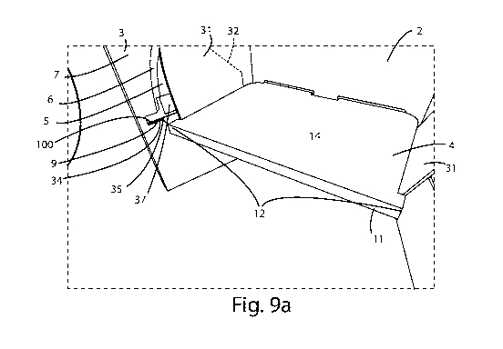
Making reference to figures 8 ¨ 9 and 12 ¨ 16, one observes a
display unit made of paper or paper-like material (in figures 8 and 9),
indicated by the reference number 1, and associated blanks (in figures 12
- 16) in a third embodiment, whereas making reference to figures 10 ¨ 11
and 17 ¨ 21, a display unit made of paper or paper-like material (in figures
10 and 11) and associated blanks (in figures 17 ¨ 21) in a fourth
embodiment are shown.
Hereinafter, the technical features in common with the
embodiments of the display unit according to the invention described
previously will be denoted by the same reference numbers.
In particular, in said third and fourth embodiments of the
commercial display unit, the body of said commercial display unit 1 is
made starting from 3 blanks, represented in figures 12 - 13 and 17 - 18,
wherein a first blank 101 is adapted to form the back wall 2 and the
intermediate layer 6 of the sidewall 3 of said display unit 1, whereas a
second blank 102 and a third blank 103 are adapted to form the outer
layer 5 and the inner layer 7 of said sidewall 3, after having been
appropriately folded and coupled, preferably glued, on the portion adapted
to form said intermediate layer 6 of said first blank 101. Said shelf 4, by
contrast, is obtained by appropriately folding and coupling two blanks, both
represented in figure 14 as well as in figure 19, so that said shelf 4
comprises four layers of a paper or paper-like material.
In these embodiments, furthermore, said back wall 2 can have
longitudinal slots 160 adapted to receive longitudinal fins 161 placed on
said shelf 4 and comprising fold lines 162 at said rear edge 17 of the shelf
4, in such a way as to fold over relative thereto.
Again in these embodiments, said inner layer 7 of each sidewall
3 has an inner fin 31, obtained by means of cuts and folds of said inner
layer 7, for each shelf 4. In particular, each inner fin 31 has an edge 32 in
CA 03147327 2022-01-12
WO 2020/012514 PCT/IT2019/050076
12
common with said inner layer 7, which consists in a fold line 32 of said
inner layer 7, whereas the other edges are obtained from cuts made on
said inner layer 7.
A terminal portion 23 of each inner fin 31, defined by a further
fold line 36, is adapted to be inserted and being coupled inside an
intermediate space between said four layers of the shelf 4, irremovably
coupling the shelf 4 to the sidewall 3.
In the embodiments shown in figures 8 ¨ lithe shaped portion
is an inner slot 100 obtained on said inner layer 7. Said inner slot 100 has
at least one lower edge portion 34 that is coplanar with a lower edge
portion 35 of said intermediate slot 9, so that at least a portion of said
protruding side fins 12 rests at least on a portion of both said lower edges
34, 35.
Furthermore, said inner fins 31 can comprise a further
intermediate layer 60 of paper or paper-like material, adapted to be
inserted in specific slots 61 obtained on said intermediate layer 6 of said
sidewalls 3. Each further intermediate layer 60 of said inner fins 31 can be
obtained by means of specific cuts from said intermediate layer 6 of the
respective sidewall 3, forming the associated slot 61.
Furthermore, the coupling between said inner fins 31 and said
sidewalls 3 can be rendered more stable by means of a magnetic coupling
means 37, consisting, for example, of pairs of magnetic elements with
opposite polarity or pairs of magnetic elements and ferromagnetic
elements couplable to each other.
In particular, said magnetic coupling means can be respectively
positioned on said slots 61 of said intermediate layer 6 of the sidewalls 3
and on said further intermediate layer 60 of said inner fins 31. Said
magnetic coupling means 37 advantageously make it possible to improve
the stability of the display unit 1, when formed.
Finally, in said third and fourth embodiments, said display unit 1
is obtained with a single movement that makes it pass from a first folded
configuration (shown in figure 22b), wherein each sidewall 3 and each said
at least one shelf 4 are substantially parallel to or coplanar with the back
wall 2, to a second configuration of use (shown in figure 22c), wherein said
sidewalls 3 are substantially transversal to said back wall 2 and each shelf
4 is substantially transversal both to said back wall 2 and to said sidewalls
3.
CA 03147327 2022-01-12
WO 2020/012514 PCT/IT2019/050076
13
In particular, during said single movement, said sidewalls 3
move with a substantially lateral movement so that each pair of slots 9 and
100 of the sidewalls 3 locks within it the portion of said protruding side
fins
12 of the respective shelf 4.
Furthermore, each shelf 4 moves with a substantially top-down
movement towards the configuration of use of the display unit 1; in
particular, the inner fins 31 pass from being substantially parallel to the
support surface 14 of the shelf 4 and to the surface of the sidewalls 3
folded along the fold line 32, to being housed in the respective portion of
the inner slot 100 and substantially transversal to the support surface 14 of
the respective shelf 4 folded along the fold line 36.
In addition, the display unit 1 can take on a third rest
configuration (shown in figure 22a), wherein the display unit 1, from the
folded configuration, is further folded relative to a further fold line 38
substantially parallel to the rear edge 17 of each shelf 4, until obtaining
two portions of the outer face of the back wall 2 substantially parallel.
This rest configuration is obtained by folding with a mountain-
fold the display unit 1 from the folded configuration relative to the inner
face of the back wall 2.
In this configuration the display unit is advantageously
convenient to store and occupies minimal space for its transport.
In the foregoing, the preferred embodiments have been
described and variants of the present invention have been suggested, but
it is understood that persons skilled in the art may apply modifications and
changes without going outside the scope of protection hereof, as defined
by the appended claims.