Note : Les descriptions sont présentées dans la langue officielle dans laquelle elles ont été soumises.
- 1 -
DEVICE FOR ASSISTING DOOR OPENING
TECHNICAL FIELD
The present disclosure relates to a device for assisting the opening and or
closing
of doors such as, for example, aircraft doors.
BACKGROUND
Doors which can open and/or close about a hinge are used in many different
applications. For example, doors which open or close under the effect of
gravity or
their weight are known in various applications such as for example, for use in
aircraft. In aircraft, doors of this type may include both emergency exit
doors which
open upwardly and passenger doors which open downwardly to form a staircase
for
exit from the aircraft.
Various devices and mechanisms to aid in opening and closing such doors are
known in the art. These devices typically comprise an electrical actuator
which
controls the opening and closing of the door. In the event of failure of the
electrical
actuator therefore, an aircraft door may fall at uncontrolled speed,
potentially
causing injury to bystanders or damage to the aircraft and surrounding
objects.
US 9,969,482 B2 discloses an aircraft door and a device for assisting the
operation
thereof. The device comprises a tubular body, a piston sliding inside the
tubular
body and defining a working chamber filled with hydraulic fluid and an
accumulator
comprising a compensation chamber filled with hydraulic fluid and in
communication with the working chamber, and a chamber filled with pressurised
gas.
The device of US 9,969,482 B2 may be used together with a motorised pulley and
a
connecting cable to assist with the opening and closing of an aircraft door.
Although various devices for assisting door opening are known, there is a need
for
improved devices for assisting door opening and / or closing.
Date Recue/Date 4;Itskielat$202129/25807
- 2 -
SUMMARY
According to a first aspect of the disclosure, there is provided a device for
assisting
the opening and closing of a door in a structure, the device comprising:
a door shaft configured to rotate about a longitudinal axis thereof in a first
direction
and in a second opposite direction, and configured to be mounted to the
structure to
form a hinge about which the door may rotate in both the first and second
directions
relative to the structure; a first actuator linked to the door shaft and
configured to
control a speed of rotation of the door shaft in the first direction; and a
second
actuator linked to the door shaft and configured to drive rotation of the door
shaft in
the second direction, wherein the second actuator is an electromechanical
actuator.
It will be understood that this device provides a relatively simple and
compact
means for assisting in opening and closing a door. This may be particularly
beneficial in applications where space is limited and/or where the weight of
any
components should be minimised such as, for example, in aerospace
applications.
Further, as both the first and second actuators are linked to the door shaft,
no
additional components such as cables and/or pulleys extending between a door
and a structure are required for the device to act to open and/or close a
door.
In any example of the disclosure, the first actuator may comprise a hydraulic
actuator and may comprise a damping system for controlling the speed of
rotation
of the door shaft in the first direction.
In any example of the disclosure, the hydraulic actuator may further comprise
an
accumulator for storing at least one of potential energy of the door and
energy
generated while the door is moving in the first direction.
The accumulator may comprise a pre-pressurised gas in a chamber and may be
adapted to store energy by further pressurising the gas due to rotation of the
door
shaft in the first direction.
The hydraulic actuator may be configured to assist in driving rotation of the
door
shaft in the second direction using the energy stored by the accumulator.
Date Recue/Date 4;ItskieliA5202129a5807
- 3 -
In any example of the disclosure, the second actuator may further be
configured to
control the speed of rotation of the door shaft in the first direction.
The device may further be configured such that one of the first actuator and
the
second actuator will function to control the speed of rotation of the door
shaft in the
first direction in the event of a failure of the other of the first actuator
and the second
actuator.
In any example of the disclosure, the device may further comprise a controller
adapted to control the second actuator to control the speed of rotation of the
door
shaft.
The device may further comprise a sensor for sensing the extent of rotation of
the
door shaft and / or the extent of opening of the door, the controller being
adapted to
control the second actuator to control the speed of rotation of the door shaft
based
on the extent of rotation of the door shaft and / or the extent of opening of
the door.
The sensor may take any suitable form and may be provided in any suitable
location to sense the extent of rotation of the door shaft. Thus, one or more
sensors
may be provided on the door shaft, and / or in the first and / or the second
actuator,
and / or connected to the door.
In any example of the disclosure, the second actuator may comprise a linear
electromechanical actuator or a rotary electromechanical actuator.
From a further aspect of the disclosure, a door comprising a device according
to
any example of the disclosure is provided, wherein the door further comprises
a
door panel connected to the door shaft for rotation therewith such that the
door
panel is configured to rotate between an open position and a closed position.
In any example of the disclosure, the weight of the door may act to rotate the
door
shaft in the first direction.
In any example of the disclosure, the device may be adapted to activate and /
or
control the second actuator to control the speed of movement of the door
towards
the end of its travel in the first direction, and / or to control the second
actuator to
Date Recue/Date 4;ItskieliA5202129a5807
- 4 -
control the speed of movement of the door towards the end of its travel in the
second direction.
In any example of the disclosure, the door may be an aircraft door and the
structure
may be an aircraft.
From a still further aspect of the disclosure, an aircraft is provided, the
aircraft
comprising: a door according to any example of the disclosure; and an aircraft
body
having an opening housing the door, wherein the first actuator and the second
actuator are fixed to the aircraft body, and wherein rotation of the door
shaft causes
the door to move between a closed position in which it closes the opening and
an
open position in which the opening is not closed by the door.
In any example of the disclosure, the aircraft may further comprise a floor
within the
body, wherein the device is located under the floor in the aircraft.
BRIEF DESCRIPTION OF DRAWINGS
An example of the disclosure will now be described by way of example only and
with reference to the accompanying drawings in which:
Figure 1 shows a schematic cross section through part of an aircraft and
aircraft
door when the door is in the closed position;
Figure 2 shows the part of the aircraft and aircraft door of Figure 1 when the
door is
in the open position;
Figure 3 is a perspective view of a device according to the disclosure when in
a first
position;
Figure 4 is a perspective view of the device of Figure 3 when in a second
position;
Figure 5 shows a schematic cross section through an example hydraulic actuator
for use in a device according to the disclosure;
Date Recue/Date 4;ItskieliA5202129a5807
- 5 -
Figure 6 shows a schematic cross section through an example electromechanical
actuator for use in a device according to the disclosure; and
Figure 7 shows a schematic cross section through part of an aircraft and
aircraft
door including an alternative device according to the disclosure.
DETAILED DESCRIPTION
Figure 1 is a schematic cross sectional view through a part of an aircraft
fuselage
10 showing a door in which a device according to the disclosure may be used.
It will
be understood that a device according to the disclosure could be used with
many
different types of doors in many different structures. In the example of the
disclosure as shown in the drawings and discussed below, the device is used
with a
door in an aircraft.
In Figure 1, an aircraft door 12 is shown in a first closed position. The door
12 is
provided in an opening (not shown) in the aircraft fuselage 10. The door 12 is
of a
type typically used in passenger aircraft and is configured to be opened by
rotating
outwardly and downwardly to open in a first direction. The door 12 can be
closed by
being rotated upwardly in a second direction. It will be understood that,
although not
shown, the device according to the disclosure could be used in doors for
entities
other than aircraft and in doors which open by rotating in another direction,
for
example, upwardly or which rotate about a vertical axis. Thus, the first and
second
directions are not limited to the downward and upward directions of the
example
shown.
The door 12 is configured to rotate about an axis (not shown) provided below
the
floor 14 of a cabin 16 within the aircraft. The axis of rotation of the door
12 typically
extends in a substantially horizontal direction. Stairs 18 may be provided
within the
door 12.
As seen in Figure 1, when the door 12 is fully closed, it is substantially
aligned with
the aircraft fuselage 10 so as to close the opening therein and the stairs 18
are
stored internally of the aircraft.
Date Recue/Date 4;ItskieliA5202129a5807
- 6 -
Figure 2 is a schematic cross sectional view through a part of an aircraft
fuselage
showing the door 12 in a second, open position. When the door 12 is in the
fully
open position, the stairs 18 are positioned such that passengers can use the
stairs
5 to enter or exit the cabin 16 of the aircraft.
It will be appreciated that the door 12 can be stored in a first orientation
in the fully
closed position in which the stairs extend substantially vertically internally
of the
aircraft. The door 12 can rotate downwardly from the first orientation through
an
10 angle in a range of between about 90 and about 170 or in a range of
between
about 110 and about 150 to a fully open position in which the outer end 20
of the
door 12 may contact or almost contact the ground 22 when the aircraft is at
rest on
the ground 22. It will be understood that, where necessary, the door 12 may be
configured to rotate through an angle of more than 170 or less than 90 from
the
closed to the open position.
When in the closed position, the door 12 may be held in place by a latch
mechanism (not shown). This can be released manually or by an automated system
to open the aircraft door 12.
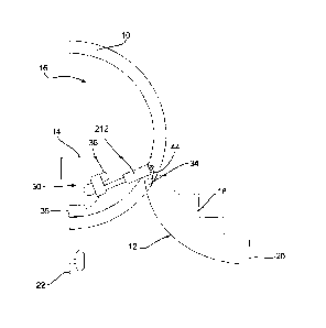
A device 30 for assisting the opening and closing of the aircraft door 12 is
provided
and can be seen in part in Figures 1 and 2. As shown, the device 30 may be
provided under the floor 14 of the aircraft cabin 16.
The device 30 is shown in greater detail in Figures 3 and 4. In Figure 3, the
device
is in a first position corresponding to the aircraft door 12 being fully
closed. In
Figure 4, the device 30 is in a second position corresponding to the aircraft
door 12
being fully open.
30 As seen in Figure 3, the device 30 comprises two actuators which may
function
independently of each other. In the example shown in Figures 3 and 4, the
device
30 comprises a first actuator 32, linked to a door shaft 34 at a first
distance along
the shaft and a second electromechanical actuator 36, linked to the door shaft
34 at
a second distance along the shaft, spaced along the shaft from the first
actuator 32.
The second actuator 36 is an electromechanical actuator.
Date Recue/Date 4;ItskieliA5202129a5807
- 7 -
The first actuator may be passive and is configured to control the speed of
movement of the door 12 in the first direction, for example as the door 12
moves
under the effect of its own weight. The first actuator may further be
configured to
store and provide an aiding force to assist in driving rotation of the door 12
in the
second direction. In examples in which the door moves in the first direction
under
the effect of its own weight, the first actuator may be configured to at least
partially
compensate for the weight of the door.
The second actuator may be active. The second actuator may be configured to
provide force & speed to move the door 12 in the second direction. The second
actuator may further be configured to control the speed of movement of the
door 12
in the first direction, for example if a failure of the first actuator makes
this
necessary or if a combined action of both the first and second actuators is
required
to control the speed of movement of the door 12.
In various examples of the disclosure, each of the first 32 and second 36
actuators
may be rotary or linear actuators. In various examples of the disclosure, the
first
actuator 32 may be any of a hydraulic actuator, a pneumatic actuator or an
electromechanical actuator.
In the example shown in Figures 3 and 4, the first actuator 32 comprises a
linear
hydraulic actuator 32 and the second actuator 36 comprises a linear
electromechanical actuator 36. As described further below, the first and
second
actuators 32, 26 are linked to the door shaft 34 at or adjacent to the
respective first
38 and second 40 ends thereof. In alternative examples however, the first and
second actuators 32, 26 may be linked to the door shaft 34 at any desired
location
along the door shaft 34 and relative to each other. As will be described
further
below with reference to Figures 5 and 6, the first and second actuators 32, 36
are
also fixed to the aircraft fuselage 10.
As seen in Figures 1 and 2, the door shaft 34 extends through the door 12 such
that
the longitudinal axis (not shown) of the door shaft 34 is coaxial with the
axis of
rotation (not shown) of the door 12. The door shaft 34 typically extends
approximately horizontally or approximately parallel to the floor 14 of the
aircraft
Date Recue/Date 4;ItskieliA5202129a5807
- 8 -
cabin 16. It will be understood that approximately is intended to mean within
+ or ¨
. In the example shown, the door shaft 34 may be approximately aligned with
the
central longitudinal axis of the aircraft fuselage.
5 The door shaft 34 is fixed to the door 12 such that the door 12 will
rotate with the
door shaft 34. Further, the door shaft 34 is rotatably fixed to the aircraft
fuselage 10
so as to form a hinge about which the door 12 may rotate in both a first and a
second direction relative to the aircraft fuselage 10. The door shaft 34 may
be
mounted on one or more bearings so as to reduce wear and/or friction.
In some examples, the device 30 further comprises or is connected to a
controller
and / or a power supply 35 as will be described further below.
To open the aircraft door 12, the door 12 is released and will then open
outwardly
(by rotating downwardly) under its own weight (i.e. the weight of the door).
This may
be achieved either manually or automatically, for example, via the controller
35. For
safety reasons, it is desirable that the door 12 may open quickly. Due to the
weight
of the door 12 and the action of gravity however, it is desirable to be able
to control
and / or slow down the speed of opening of the door 12 so as to avoid possible
injuries to people on the ground near the aircraft or damage to the door
mechanism
or aircraft structure. In various examples of the disclosure, either one or
both of the
first and second actuators 32, 36 may be used to control the speed of opening
of
the door 12. In the example shown, during normal operation, the first actuator
32
may be used to control the speed of movement of the door 12 (or to damp the
movement of the door 12) while it is opening and the second actuator 36 may be
passive, following the rotation of the door shaft 34 without exerting any
significant
force thereon.
In any example of the disclosure, a position sensor (not shown) may be
provided to
sense the extent of rotation of the door shaft 34, thus indicating the
position of the
door 12 or the extent of travel of the door 12 between the open and closed
positions. The sensor may take any suitable form and may be provided in any
suitable location to sense the extent of rotation of the door shaft 34. Thus,
one or
more sensors may be provided at one or more of the following locations: on the
Date Recue/Date 4;ItskieliA5202129a5807
- 9 -
door shaft 34; and / or in the first and / or the second actuator 32, 36; and
/ or
connected to the door 12.
The opening speed of the door 12 can be controlled in any example of the
disclosure as a function of the door position. Further, the extent of rotation
of the
door shaft 34 can be used to optimize and/or adjust the control of the opening
speed of the door 12.
In one example of the disclosure, when the position sensor senses that the
door 12
is near to but not at the fully open position, for example, when the door 12
has
rotated to about 10 from its fully open position, the controller 35 may
activate or
control the electromechanical actuator 36. The speed of rotation of the door
12 over
the final extent of opening (for example, over the last 100 of rotation) may
therefore
be regulated by the electromechanical actuator 36 acting together with the
hydraulic
actuator 32. In one example, the phases of the motor(s) of the
electromechanical
actuator 36 can be short circuited. In another example, adequate active
switching of
the motor phases may be used to control the speed of rotation of the door 12
to a
target value.
It will be understood that the additional control in the speed of rotation of
the door
12 over the final extent of opening may slow the speed of movement of the door
12
to allow the door to gradually slow down as it reaches the fully open position
such
that the door will come to a smooth stop as it opens. This will further reduce
the
likelihood of damage to the aircraft, the door 12 or the door mechanism due,
for
example, to the door 12 contacting the ground 22 at too great a speed.
Further, it will be understood that in alternative examples, the controller 35
may
control the electromechanical actuator 36 when already active so as to control
the
speed of rotation of the door 12 (for example, over the last 10 of rotation).
In any example of the disclosure, the hydraulic actuator 32 may include an
accumulator 129 or gas spring mechanism (as will be described further below).
The
accumulator 129 may be precharged to have a level of stored potential energy
when the door 12 is in the closed position and to store additional energy from
the
weight of the door 12 whilst the door is opening. In normal operation, when an
operator wishes to close the door 12, the controller 35 will activate the
Date Recue/Date 4;ItskieliA5202129a5807
- 10 -
electromechanical actuator 36 which will act to rotate the door shaft 34 and
lift the
door 12 back into the closed position. The hydraulic actuator 32 may assist
the
electromechanical actuator 36 using the energy stored by the accumulator 129.
The
level of stored potential energy when the door 12 is in the closed position
may be
set to provide a desired force to compensate, at least partially, for the
weight of the
door 12 and so to reduce the work required from the electromechanical actuator
36
while the door 12 is closing. The precharge of the accumulator 129 is further
set at
a level to allow the hydraulic actuator 32 to at least partially compensate
for the
weight of the door 12 in its open position and over the full extent of travel
of the
door 12 when closing.
The speed of rotation of the door 12 whilst closing may be controlled by the
electromechanical actuator 36. When the position sensor (not shown) senses
that
the door 12 is near to but not at the fully closed position, for example when
the door
has rotated to about 10 from its fully closed position, the controller 35 may
control
the electromechanical actuator 36 (for example, switching to a different speed
schedule) such that the speed of rotation of the door 12 over the final extent
of
closing (for example, over the last 10 of rotation) may be regulated to
ensure that
the door 12 does not close too quickly, potentially causing damage to the
aircraft
and / or people in the cabin 16.
The device 30 according to the disclosure may provide additional safety in the
event of a failure of either the hydraulic actuator 32 or the
electromechanical
actuator 36. In the event that the hydraulic actuator 32 fails either before
or during
opening of the door 12, the controller 35 may receive notification of the
failure. In
one example of the disclosure, a failure of the hydraulic actuator 32 may be
identified by monitoring the speed of movement of the electromechanical
actuator
36 (for example, at the ball screw 206 or at the gear box 208). If an
overspeed in
the speed of movement of the electromechanical actuator 36 is detected, a
signal
error may be sent to controller 35. As a result of receiving the signal error,
the
controller 35 may activate or control the electromechanical actuator 36, which
may
be sized to sufficiently control the speed of rotation or movement of the door
12
when acting independently of and without the hydraulic actuator 32. Thus, the
door
12 may be opened safely and at a controlled speed due to the action of the
Date Recue/Date 4;ItskieliA5202129a5807
- 11 -
electromechanical actuator 36 when the hydraulic actuator 32 is not
operational due
to a failure thereof.
In one example of the disclosure, the electrical motor 202 in the
electromechanical
actuator 36 may be short-circuited to reduce the door opening speed as much as
possible over the stroke of the electromechanical actuator 36.
In the event that the electromechanical actuator 36 fails either before or
during
opening of the door 12, the controller 35 may receive notification of the
failure. In
one example of the disclosure, a failure of the electromechanical actuator 36
during
opening of the door 12 may be identified by monitoring the current/voltage at
an
electromechanical actuator motor control unit (not shown). During normal
opening
of the door 12, the electromechanical actuator 36 is passive and so the motor
202
will generate current/voltage. Thus, if no current/voltage is detected or if
it is below
a pre-set threshold, a signal identifying a failure of the electromechanical
actuator
36 may be generated. The hydraulic actuator 32 may be sized to sufficiently
control
the speed of rotation or movement of the door 12 when acting independently of
and
without the electromechanical actuator 36. Thus, the door 12 may be opened
safely
and at a controlled speed due to the action of the hydraulic actuator 32 when
the
electromechanical actuator 36 is not operational due to a failure thereof.
The device 30 according to the disclosure may also provide additional safety
in the
event of a failure of either the hydraulic actuator 32 or the
electromechanical
actuator 36 when the door 12 is already open. In the event that the hydraulic
actuator 32 has failed, the door 12 may remain open when an operator attempts
to
close the door. The electromechanical actuator 36 will detect an overload when
activated to lift the door 12 due to a lack of assistance from the gas spring
mechanism of the hydraulic actuator 32. Thus, the door 12 will remain open,
indicating to personnel that there is a fault.
In the example shown, in the event that the electromechanical actuator 36 has
failed, the door 12 will remain open when an operator attempts to close the
door.
The hydraulic actuator 32 is not sized to be capable of lifting the door 12
independently of the electromechanical actuator 36. Thus the door will remain
open, indicating to personnel that there is a fault.
Date Recue/Date 4;ItskieliA5202129a5807
- 12 -
An example hydraulic actuator 32 of the device 30 according to the disclosure
is
shown in greater detail in Figure 5. In one example of the disclosure, the
hydraulic
actuator 32 may comprise a first cylinder 102 containing a piston 104 attached
to a
piston rod 106 at a first end of the piston rod 106. The piston rod 106
extends
outwardly from a first end 112 of the first cylinder 102 and is provided with
first
fastening means 114 at the opposite second end thereof. The piston rod may be
linked to the door shaft 34 via the first fastening means 114 and a linkage 42
connecting the door shaft 34 to the first fastening means 114 such that the
door
shaft 34 can pivot about the connection between the first fastening means 114
and
the linkage 42.
The piston 104 is adapted to move axially within the first cylinder 102. The
first
cylinder 102 is separated into a first variable chamber 108 defined on a first
side of
the piston 104 and a second variable chamber 110 through which the piston rod
106 extends, the second chamber being defined on a second side of the piston
104. It will be understood that the first variable chamber 108 is circular in
cross
section and has a constant cross sectional area which is greater than the
(constant)
cross sectional area of the second variable chamber 110, which is annular in
cross
section due to the presence of the piston rod 106 in the second variable
chamber
110. This difference in the cross sectional areas of the first and second
variable
chambers 108, 110, allows the hydraulic actuator to develop a force when the
accumulator (described below) is pressurized so as to allow for compensation
of
the weight of the door 12.
The free space inside the first cylinder 102, i.e. both the first and second
chambers
108, 110, is filled with hydraulic fluid (not shown). In one example, the
hydraulic
fluid may be oil.
A damping system, for example, a choke valve 116 is provided within the piston
104 and extending from the first variable chamber 108 to the second variable
chamber 110.
Second fastening means 118 are provided on the first cylinder 102 adjacent a
second end 120 thereof. The hydraulic actuator 32 may be fixed to the
aircraft, for
Date Recue/Date 4;ItskieliA5202129a5807
- 13 -
example the aircraft fuselage, at a desired location via the second fastening
means
118.
In addition, an accumulator for storing energy is provided. The accumulator
comprises a second cylinder 130 separated into first and second variable
chambers
132, 134 by a piston 136. The first variable chamber 132 of the second
cylinder 130
is linked by a pipe 138 to the second variable chamber 110 of the first
cylinder 102
such that hydraulic fluid may flow from the second variable chamber 110 of the
first
cylinder 102 into the first variable chamber 132 of the second cylinder 130.
The first variable chamber 132 of the second cylinder 130 contains a gas-tight
metal bellows 140 into which the hydraulic fluid may flow. In alternative
examples, a
bellows formed from an elastomeric or natural rubber membrane may be provided.
The second variable chamber 134 of the second cylinder 130 is filled with a
gas
which can be compressed and pressurised by the action of the piston 136 moving
within the second cylinder 130 as hydraulic fluid flows into the first
variable chamber
132 of the second cylinder 130 due to movement of the piston 104 of the first
cylinder 102. In the example shown, an initial pressure is applied to the gas
in the
second variable chamber 134 such that the gas is at the initial pressure or a
higher
pressure at all times. Thus, the accumulator is precharged to have a level of
stored
energy when the door 12 is in the closed position. As the gas can be
compressed
and pressurised by the action of the piston 136 moving within the second
cylinder
130, the pressurised gas can also act to store energy generated as the door is
opening and to use the stored energy in assisting closing of the door. The
accumulator is therefore configured to supply a static effort to the piston
104 of the
hydraulic actuator to compensate for the weight of the door acting in the
first
direction and to assist in closing the door, to move it in the second
direction, due to
the energy stored in the pressurised gas.
An example electromechanical actuator 36 of the device according to the
disclosure
is shown in greater detail in Figure 6. The electromechanical actuator 36
includes
an electric motor control unit (EMCU) 202 which controls an A/C electrical
motor
204. The electrical motor 204 is configured to drive a ball screw assembly 206
via
gears 208 so as to convert rotational movement of the motor 204 into linear
movement. A cylindrical body or arm 212 extends over the screw 210 and is
Date Recue/Date 4;ItskieliA5202129a5807
- 14 -
threaded as to engage with the screw and to move linearly relative to the
screw in
use so as to be capable of being axially extended or retracted.
First fastening means 220 for fastening the electromechanical actuator 36 to a
stationary part of the aircraft are provided adjacent the electrical motor 204
and
gears 208. Second fastening means 222 are provided at an end of the
cylindrical
body 212. The cylindrical body 212 may be connected to the door shaft 34 via a
linkage 44 extending between the second fastening means 222 and the door shaft
34.
In normal operation of the device, i.e. when both the hydraulic actuator 32
and the
electromechanical actuator 36 are fully functional, the piston rod 106 of the
hydraulic actuator 32 is fully extended when the door 12 is in the closed
position
and the arm 212 of the electromechanical actuator 36 is fully retracted as
seen in
Figure 3. It will be appreciated that, in alternative examples not shown here,
the
second actuator could be configured to be extended when the door 12 is in the
closed position and retracted when the door is in the open position.
Similarly, in
examples where the first actuator comprises a linear electromechanical
actuator,
the first actuator could be configured to be retracted when the door 12 is in
the
closed position and extended when the door is in the open position.
As the door begins to open, the arm of the electromechanical actuator is
allowed to
extend so as to follow the rotation of the door shaft 34 without exerting any
force
thereon. The opening movement or rotation of the door 12 will cause the piston
rod
106 of the hydraulic actuator 32 to be pushed inwardly into the first cylinder
102.
The hydraulic fluid will thus be forced through the choke valve 116 causing a
reaction force acting against the movement of the piston to damp the rotation
of the
door shaft 34, thus controlling the speed of movement thereof. At the same
time,
the action of the hydraulic fluid being pushed into the second cylinder 130
will
cause the gas therein to be pressurised, thus storing potential energy from
the
weight of the door 12 whilst opening.
The door shaft will continue to rotate until the door is in the fully open
position as
shown in Figure 4. When in the fully open position, the piston rod 106 of the
Date Recue/Date 4;ItskieliA5202129a5807
- 15 -
hydraulic actuator 32 is fully retracted and the arm 212 of the
electromechanical
actuator 36 is fully extended.
To close the door 12 under normal operating conditions, the electromechanical
actuator 36 is activated to retract the arm 212, thus pulling the linkage 44
back and
causing the door shaft to rotate the door back to its closed position. The
rotation of
the door shaft 34 will cause the piston rod 106 of the hydraulic actuator 32
to be
pulled towards the extended position, the stored potential energy from the
pressurised gas acting to push against the piston 104 such that work is
applied by
the piston rod 106 to move it toward the extended position and to aid in
closing the
door 12.
An alternative device according to the disclosure is shown in Figure 7. Where
components correspond to those already described in relation to the example of
Figures 1 to 4, the same reference numbers are used in Figure 7 and no further
description is provided.
As in Figures 1 to 4, a door 12 (shown here in the closed position) is
provided in an
opening (not shown) in the aircraft fuselage 10.
A device 730 for assisting the opening and closing of the aircraft door 12 is
provided. As shown, the device 730 may be provided under the floor 14 of the
aircraft cabin 16.
The device 730 again comprises two actuators which may function independently
of
each other. In the example shown, the device 730 comprises a first actuator
732,
linked to a drive shaft 750 at a first distance along the drive shaft 750 and
a second
actuator 736, linked to the drive shaft 750 at a second distance along the
drive shaft
750, spaced along the drive shaft 750 from the first actuator 732. The second
actuator 736 comprises a rotary electromechanical actuator 736 and the drive
shaft
750 may be in line with the rotational axis (not shown) of the rotary
electromechanical actuator 736. Thus, the rotary electromechanical actuator
736
may be provided at a first end of the drive shaft 750 and adapted to drive
rotation of
the drive shaft 750. The first actuator 732 may take the same form as and have
all
Date Recue/Date 4;Itskielat$202129/25807
- 16 -
the features of the hydraulic actuator 32 shown and described above in
relation to
Figure 5.
The drive shaft 750 is configured to rotate about a longitudinal axis thereof
(not
shown). As seen in Figure 7, the piston 106 of the hydraulic actuator 732 is
connected to the drive shaft 750 via an actuator crank 752. The actuator crank
752
may comprise a first arm 754. A first end 758 of the first arm 754 may be
pivotally
attached to the piston 106 of the hydraulic actuator 732. The second opposite
end
of the first arm 754 is fixed to a second arm 756 at a first end thereof, such
that the
first arm 754 extends at a fixed angle a to the second arm 756. In the example
shown, the angle a is between 90 and 110 , but it will be appreciated that
any
suitable actuator crank arrangement may be used.
The actuator crank 752 is pivotally connected to the drive shaft 750 at the
junction
between the first 754 and second 756 arms thereof. A second end 760 of the
second arm 756 is pivotally connected to a first end 762 of a rod 764. The
second,
opposite end 766 of the rod 764 is pivotally attached to a first end 768 of a
door
crank 770, and the second end 772 of the door crank 770 is attached the door
shaft
34 so as to rotate therewith. Thus, the hydraulic actuator 732 is linked to
the door
shaft 34 and able to control the speed of rotation of the door shaft 34 and
the speed
of movement of the door in a manner similar to that described above in
relation to
the example of Figures 1 to 4.
As seen in Figure 7 and in a similar manner to the example of Figures 1 to 4,
the
hydraulic actuator 732 also comprises first fixing means 114 for fixing the
hydraulic
actuator 732 to a part of the aircraft structure. In the example shown, the
hydraulic
actuator 732 is fixed to a structure 780 below the floor 14 of the aircraft
cabin 16.
The rotary electromechanical actuator 736 may also be fixed to a structure of
the
aircraft. In the example shown, the rotary electromechanical actuator 736 is
connected directly to the drive shaft 750. By driving rotation of the drive
shaft 750,
the rotary electromechanical actuator 736 will cause the crank arm 752 to
rotate,
and so is able to drive rotation of the door shaft 34 and to control the speed
of
movement of the door in either direction via the drive shaft 750.
Date Recue/Date 4;ItskieliA5202129a5807
- 17 -
The device 730 may further comprise a controller (not shown).
To open the aircraft door 12, the door is released and will then open
outwardly
under its own weight as in the example of Figures 1 to 4. In normal operation,
the
rotary electromechanical actuator 736 may be used to control the speed of
movement of the door 12 (or to damp the movement of the door) while it is
opening.
The device 730 according to this example of the disclosure may provide
additional
safety in the event of a failure of either the hydraulic actuator 732 or the
electromechanical actuator 736. In the event that the electromechanical
actuator
736 fails either before or during opening of the door 12, the controller may
receive
notification of the failure. The hydraulic actuator 732 may be sized to
sufficiently
control the speed of rotation or movement of the door when acting
independently of
and without the electromechanical actuator 736. Thus, the door 12 may be
opened
safely and at a controlled speed due to the action of the hydraulic actuator
732
when the electromechanical actuator 736 is not operational due to a failure
thereof.
The device 730 according to the disclosure may also provide additional safety
in the
event of a failure of either the hydraulic actuator 32 or the
electromechanical
actuator 736 when the door 12 is already open. In one example, in the event
that
the hydraulic actuator 732 has failed, the door 12 will remain open when an
operator attempts to close the door. The electromechanical actuator 736 will
detect
an overload when activated to lift the door 12 due to a lack of assistance
from the
gas spring mechanism of the hydraulic actuator 732. Thus, the door 12 will
remain
open, indicating to personnel that there is a fault. In an alternative
example, the
electromechanical actuator 736 could be sized to reclose the door 12 alone,
for
example with a reclosing time increased by 2 or 3 times compared to the
closing
time in normal operating conditions.
In the event that the electromechanical actuator 736 has failed, the door 12
will
remain open when an operator attempts to close the door. The hydraulic
actuator
732 is not sized to be capable of lifting the door 12 independently of the
electromechanical actuator 736. Thus the door will remain open, indicating to
personnel that there is a fault.
Date Recue/Date 4;ItskieliA5202129a5807
- 18 -
As an additional or alternative means of detecting a failure, which is
applicable to
any example of the disclosure including a pneumatic or hydraulic actuator, a
pressure switch or pressure transducer (not shown) may be provided to monitor
the
pressure of the fluid within the pneumatic or hydraulic actuator and to
indicate a
failure of the pneumatic or hydraulic actuator if the pressure of the fluid
falls below a
desired minimum value. Additionally, the pressure of gas in the accumulator
could
be monitored to indicate a failure of the accumulator if the pressure of the
gas falls
below a desired minimum value
While the disclosure has been described in detail in connection with only a
limited
number of examples, it should be readily understood that the disclosure is not
limited to such disclosed examples. Rather, the disclosure can be modified to
incorporate any number of variations, alterations, substitutions or equivalent
arrangements not heretofore described, but which are commensurate with the
scope of disclosure.
For example, it will be understood that any desired combination of actuators
could
be used in addition to those shown in the examples discussed above. For
example,
a device according to the disclosure could be provided having two
electromechanical actuators such as two linear electromechanical actuators,
two
rotary electromechanical actuators or with a pneumatic actuator in place of
the
hydraulic actuator of the examples.
Additionally, while various examples of the disclosure have been described, it
is to
be understood that aspects of the disclosure may include only some of the
described examples. Accordingly the disclosure is not to be seen as limited by
the
foregoing description, but is only limited by the scope of the appended
claims.
Date Recue/Date 4;ItskieliA5202129a5807