Sélection de la langue

Search

Sommaire du brevet 3148577 

Énoncé de désistement de responsabilité concernant l'information provenant de tiers

Une partie des informations de ce site Web a été fournie par des sources externes. Le gouvernement du Canada n'assume aucune responsabilité concernant la précision, l'actualité ou la fiabilité des informations fournies par les sources externes. Les utilisateurs qui désirent employer cette information devraient consulter directement la source des informations. Le contenu fourni par les sources externes n'est pas assujetti aux exigences sur les langues officielles, la protection des renseignements personnels et l'accessibilité.

Disponibilité de l'Abrégé et des Revendications

L'apparition de différences dans le texte et l'image des Revendications et de l'Abrégé dépend du moment auquel le document est publié. Les textes des Revendications et de l'Abrégé sont affichés :

  • lorsque la demande peut être examinée par le public;
  • lorsque le brevet est émis (délivrance).
(12) Demande de brevet: (11) CA 3148577
(54) Titre français: ASSEMBLAGE DE REDUCTEUR DE TENSION
(54) Titre anglais: STRAIN RELIEF ASSEMBLY
Statut: Demande conforme
Données bibliographiques
(51) Classification internationale des brevets (CIB):
  • F16L 03/23 (2006.01)
  • F16C 11/10 (2006.01)
(72) Inventeurs :
  • ROA-QUISPE, CHRISTIAN (Canada)
  • LAZARTE BARRIOS, OSCAR ALBERTO (Canada)
(73) Titulaires :
  • BELDEN CANADA ULC
(71) Demandeurs :
  • BELDEN CANADA ULC (Canada)
(74) Agent: LAVERY, DE BILLY, LLP
(74) Co-agent:
(45) Délivré:
(22) Date de dépôt: 2022-02-11
(41) Mise à la disponibilité du public: 2022-08-12
Licence disponible: S.O.
Cédé au domaine public: S.O.
(25) Langue des documents déposés: Anglais

Traité de coopération en matière de brevets (PCT): Non

(30) Données de priorité de la demande:
Numéro de la demande Pays / territoire Date
63/200,081 (Etats-Unis d'Amérique) 2021-02-12

Abrégés

Abrégé anglais


A strain relief assembly is disclosed comprising a support for mounting on a
tray
or the like and an elongate support member to which is rotatably mounted a
strain
relief member. The strain relief member is secured to the support member by a
securing mechanism comprising a shaft which travels within a shaft receiving
bore
between a secured position, wherein a first shaft end of the shaft presses
against
a free end of the second portion and thereby preventing rotation of the
elongate
strain relief member and a released position wherein the shaft is positioned
away
from the free end of the second portion and such that the elongate strain
relief
member is rotatable.

Revendications

Note : Les revendications sont présentées dans la langue officielle dans laquelle elles ont été soumises.


Claims
1. A strain relief assembly, comprising:
a support comprising a base and an elongate support member comprising
a first portion attached to and extending away from said base and a
second portion extending away from an end of said first portion at an
angle to said first portion;
an elongate strain relief member attached to a free end of said second
portion for rotation about an axis, said elongate strain relief member
comprising an elongate cable receiving part arranged along said axis
and comprising a first end and a second end opposite said first end,
said elongate cable receiving part further comprising at least one cable
receiving surface and a shaft receiving bore concentric with said axis
and extending a length of said cable receiving part; and
a securing mechanism comprising a shaft arranged for travel within said
shaft receiving bore between a secured position, wherein a first shaft
end of said shaft presses against said free end of said second portion
thereby preventing rotation of said elongate strain relief member about
said axis and a released position wherein said shaft is positioned away
from said free end of said second portion and such that said elongate
strain relief member is rotatable about said axis.
2. The strain relief assembly of Claim 1, wherein said elongate strain
relief
member is rotatable between a first angled orientation and a second angled
orientation through a horizontal orientation.
3. The strain relief assembly of Claim 2, wherein an angle between said
first
angled orientation and said second angled orientation is less than or equal to
50
degrees.
5
Date Recue/Date Received 2022-02-11

4. The strain relief assembly of Claim 2, wherein a mechanical feedback
is
provided as said elongate strain relief member is rotated into said horizontal
orientation.
5. The strain relief assembly of Claim 2, wherein said mechanical feedback
is
provided by a boss on said free end of said second portion which is engaged in
a
feature on said elongate strain relief member as said elongate strain relief
member
is rotated into said horizontal orientation.
6. The strain relief assembly of Claim 1, wherein said elongate cable
receiving
part further comprises a pair of long outer edges arranged opposite one
another
on either side of and in parallel to said axis, each said outer edges
comprising at
least one cable securing feature along a length thereof.
7. The strain relief assembly of Claim 1, further comprising a nut
comprising a
threaded inner surface imbedded in said elongate strain relief member
concentric
with said axis, wherein a second shaft end extends beyond said elongate strain
relief member and comprising a knob attached to said second shaft for rotating
said shaft about said axis, wherein a complementary threaded portion of said
shaft
is engaged by said threaded inner surface of said nut and such that through
rotation of said shaft using said knob, said threaded outer surface is engaged
by
said threaded inner surface thereby moving said first shaft end along said
axis
between said secured position and said released position.
8. The strain relief assembly of Claim 1, wherein said free end of said
second
member comprises a ball and said elongate strain relief member further
comprises
a socket concentric with said axis for receiving said ball.
9. The strain relief assembly of Claim 1, wherein said base is flat and
configured for attachment to a flat surface.
6
Date Recue/Date Received 2022-02-11

10. The strain relief assembly of Claim 1, wherein said first portion
extends
away from said base in a direction substantially normal to said base.
11. The strain relief assembly of Claim 1, wherein said second portion is
arranged at a right angle to said first portion.
12. The strain relief assembly of Claim 1, wherein said elongate cable
receiving
part further comprises a first cable receiving surface and a second cable
receiving
surface on an opposite side of said axis to said first cable receiving
surface.
13. The strain relief assembly of Claim 12, wherein said first cable
receiving
surface and said second cable receiving surface are like surfaces and arranged
opposite one another about said axis.
14. The strain relief assembly of Claim 1, further comprising a first
collar
between said socket and said cable receiving part and a second collar at a
second
end of said cable receiving part opposite said first end, said first collar
and said
second collar extending above at least one cable receiving surface.
15. The strain relief assembly of Claim 14, wherein said first collar and
said
second collar are arranged concentric with said axis.
7
Date Recue/Date Received 2022-02-11

Description

Note : Les descriptions sont présentées dans la langue officielle dans laquelle elles ont été soumises.

TITLE OF THE INVENTION
STRAIN RELIEF ASSEMBLY
FIELD OF THE INVENTION
[0001]The present invention relates to a strain relief assembly. In
particular, the
present invention relates to an adjustable strain relief assembly mountable to
a
tray.
SUMMARY OF THE INVENTION
[0002] There is provided a strain relief assembly comprising a support
comprising
a base and an elongate support member comprising a first portion attached to
and
extending away from the base and a second portion extending away from an end
of the first portion at an angle to the first portion, an elongate strain
relief member
attached to a free end of the second portion for rotation about an axis, the
elongate
strain relief member comprising an elongate cable receiving part arranged
along
the axis and comprising a first end and a second end opposite the first end,
the
elongate cable receiving part further comprising at least one cable receiving
surface and a shaft receiving bore concentric with the axis and extending a
length
of the cable receiving part, and a securing mechanism comprising a shaft
arranged
for travel within the shaft receiving bore between a secured position, wherein
a first
shaft end of the shaft presses against the free end of the second portion
thereby
preventing rotation of the elongate strain relief member about the axis and a
released position wherein the shaft is positioned away from the free end of
the
second portion and such that the elongate strain relief member is rotatable
about
the axis.
BRIEF DESCRIPTION OF THE DRAWINGS
1
Date Recue/Date Received 2022-02-11

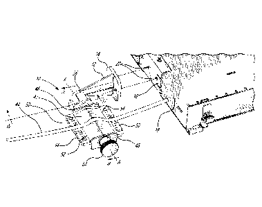
[0003] Figure 1 provides a raised perspective view of a strain relief assembly
and
tray in accordance with an illustrative embodiment of the present invention;
[0004] Figure 2 provides a raised exploded perspective view of strain relief
assembly in accordance with an illustrative embodiment of the present
invention;
[0005] Figure 3 provides a sectional view along 111-11I in Figure 1;
[0006] Figures 4A through 4C provide sectional views along IV-IV in Figure 1;
and
[0007] Figures 5A through 5C provide front perspective views of a strain
relief
assembly and tray receiving cables from different orientations and in
accordance
with an illustrative embodiment of the present invention.
DETAILED DESCRIPTION OF THE ILLUSTRATIVE EMBODIMENTS
[0008] Referring now to Figure 1, a strain relief assembly, generally referred
to
using the reference numeral 10, will now be described. The assembly 10
comprise
a support 12 comprising a flat base 14 configured for attachment to a flat
surface,
such as the side 16 of a tray 18 or the like. In this regard, the flat base 14
can be
secured to the side 16 using bolts or the like (not shown) which are engaged
in
complementary threaded bores 20 machined or otherwise formed in the side 16.
[0009] With reference now to Figure 2 in addition to Figure 1, the support 12
further
comprises an elongate support member 22 comprising a rod-like first portion 24
attached to the base 14 and extending away therefrom in a direction which is
substantially normal to the base 14 and a second portion 26 arranged at a
right
angle to the first portion 24 and interconnecting an outer end 28 of the first
portion
with a spherical ball 30. In a particular embodiment the second portion 26 is
curved
about 90 degrees between the outer end 28 and the ball 30. Re-enforcing
abutments 32 are provided to stabilise the support member 22.
2
Date Recue/Date Received 2022-02-11

[0010]Still referring to Figure 2 in addition to Figure 1, the strain relief
assembly
further comprises an elongate strain relief member 34 comprising a socket 36
at a first end 38 and configured for receiving the ball 30 in a ball and
socket
5 relationship and for limited rotation about an axis A-A. The strain
relief member 34
further comprises an elongate cable receiving part 40 arranged along the axis
A-
A. The cable receiving part 40 further comprises a pair of cable receiving
surfaces
42 of like shape and opposite one another on either side of the axis A-A for
receiving cables 44 thereon. In order to retain the cables 44 on the surfaces
42
10 first and second collars 46, 48 are provided at respective ends of the
cable
receiving part 40. Similarly, cable securing features 50 are provided along a
length
of the outer long edges 52, 54 of the cable receiving part 40. In this regard
the
cable securing features 50 provide convenient locations for securing cable
ties or
the like (not shown).
[0011] Referring now to Figure 3 in addition to Figures 1 and 2, in order to
releasably secure the ball 30 and socket 36 in a fixed relationship a securing
mechanism is provided comprising a bolt 56 embedded in the cable receiving
part
40. The bolt 56 comprises a threaded inner surface 58 arranged concentric with
the axis A-A which engages a threaded shaft 60. The shaft 60 is held for
rotation
within a shaft receiving bore 62 arranged concentric with the axis A-A and
further
comprises a user actuatable knob 64. As a person of skill in the art will now
understand, depending on the direction the knob 64 is turned, an end 66 of the
shaft 60 may be selectively moved towards or away from the ball 30 held within
the socket 36. Moving the shaft 60 towards the ball 30 causes the end 66 to
engage
the ball 30 thereby releasably secures the ball 30 in a fixed relationship to
the
socket 36.
[0012] Referring to Figure 4A in addition to Figures 2 and 3, releasing the
engagement between the support 12 and the cable receiving part 40 by rotating
the knob 64 allows the cable receiving part 40 to be rotated relative to the
support
3
Date Recue/Date Received 2022-02-11

12. In this regard, the ball 30 comprises bosses 68 which engage with features
70
on the socket 36 in order to limit rotation of the cable receiving part 40 to
the
support 12 to within predetermined limits. In an intermediate position as
shown in
Figure 4A a middle one of the bosses 68 is received within the lower feature
70. In
this regard the lower feature 70 comprises bevelled walls 72 such that the
boss 68
can be moved in to and out of the feature 70 while providing tactile feedback.
[0013] Referring to Figures 5A through 5C, illustratively the bosses 68 and
features
70 are positioned such that the strain relief member 34 can be rotated through
50
and the cable receiving surfaces 42 positioned at up to 25 from the
horizontal.
This allows cables 44 to be conveniently received and secured from above
(Figure
5A), below (Figure 5B) and the side (Figure 5C) as well as intermediate
positions.
[0014] Although the present invention has been described hereinabove by way of
specific embodiments thereof, it can be modified, without departing from the
spirit
and nature of the subject invention as defined in the appended claims.
4
Date Recue/Date Received 2022-02-11

Dessin représentatif
Une figure unique qui représente un dessin illustrant l'invention.
États administratifs

2024-08-01 : Dans le cadre de la transition vers les Brevets de nouvelle génération (BNG), la base de données sur les brevets canadiens (BDBC) contient désormais un Historique d'événement plus détaillé, qui reproduit le Journal des événements de notre nouvelle solution interne.

Veuillez noter que les événements débutant par « Inactive : » se réfèrent à des événements qui ne sont plus utilisés dans notre nouvelle solution interne.

Pour une meilleure compréhension de l'état de la demande ou brevet qui figure sur cette page, la rubrique Mise en garde , et les descriptions de Brevet , Historique d'événement , Taxes périodiques et Historique des paiements devraient être consultées.

Historique d'événement

Description Date
Inactive : Page couverture publiée 2022-09-14
Demande publiée (accessible au public) 2022-08-12
Exigences quant à la conformité - jugées remplies 2022-06-20
Inactive : CIB attribuée 2022-03-03
Inactive : CIB en 1re position 2022-03-03
Lettre envoyée 2022-03-02
Exigences de dépôt - jugé conforme 2022-03-02
Lettre envoyée 2022-02-25
Exigences applicables à la revendication de priorité - jugée conforme 2022-02-25
Demande de priorité reçue 2022-02-25
Inactive : CQ images - Numérisation 2022-02-11
Demande reçue - nationale ordinaire 2022-02-11

Historique d'abandonnement

Il n'y a pas d'historique d'abandonnement

Taxes périodiques

Le dernier paiement a été reçu le 2023-11-28

Avis : Si le paiement en totalité n'a pas été reçu au plus tard à la date indiquée, une taxe supplémentaire peut être imposée, soit une des taxes suivantes :

  • taxe de rétablissement ;
  • taxe pour paiement en souffrance ; ou
  • taxe additionnelle pour le renversement d'une péremption réputée.

Les taxes sur les brevets sont ajustées au 1er janvier de chaque année. Les montants ci-dessus sont les montants actuels s'ils sont reçus au plus tard le 31 décembre de l'année en cours.
Veuillez vous référer à la page web des taxes sur les brevets de l'OPIC pour voir tous les montants actuels des taxes.

Historique des taxes

Type de taxes Anniversaire Échéance Date payée
Enregistrement d'un document 2022-02-11 2022-02-11
Taxe pour le dépôt - générale 2022-02-11 2022-02-11
TM (demande, 2e anniv.) - générale 02 2024-02-12 2023-11-28
Titulaires au dossier

Les titulaires actuels et antérieures au dossier sont affichés en ordre alphabétique.

Titulaires actuels au dossier
BELDEN CANADA ULC
Titulaires antérieures au dossier
CHRISTIAN ROA-QUISPE
OSCAR ALBERTO LAZARTE BARRIOS
Les propriétaires antérieurs qui ne figurent pas dans la liste des « Propriétaires au dossier » apparaîtront dans d'autres documents au dossier.
Documents

Pour visionner les fichiers sélectionnés, entrer le code reCAPTCHA :


Pour visualiser une image, cliquer sur un lien dans la colonne description du document. Pour télécharger l'image (les images), cliquer l'une ou plusieurs cases à cocher dans la première colonne et ensuite cliquer sur le bouton "Télécharger sélection en format PDF (archive Zip)" ou le bouton "Télécharger sélection (en un fichier PDF fusionné)".

Liste des documents de brevet publiés et non publiés sur la BDBC .

Si vous avez des difficultés à accéder au contenu, veuillez communiquer avec le Centre de services à la clientèle au 1-866-997-1936, ou envoyer un courriel au Centre de service à la clientèle de l'OPIC.


Description du
Document 
Date
(aaaa-mm-jj) 
Nombre de pages   Taille de l'image (Ko) 
Abrégé 2022-02-10 1 18
Revendications 2022-02-10 3 116
Description 2022-02-10 4 165
Dessins 2022-02-10 5 135
Dessin représentatif 2022-09-13 1 22
Courtoisie - Certificat d'enregistrement (document(s) connexe(s)) 2022-02-24 1 354
Courtoisie - Certificat de dépôt 2022-03-01 1 578
Nouvelle demande 2022-02-10 11 537