Note : Les descriptions sont présentées dans la langue officielle dans laquelle elles ont été soumises.
MOBILE SYSTEM FOR PIPE REHABILITATION
CROSS-REFERENCE TO RELATED APPLICATION
[0001] This application claims priority to U.S. Provisional Patent Application
Serial No. 63/148,230, filed February 11, 2021, and entitled Mobile System for
Pipe
Rehabilitation, which is hereby incorporated by reference in its entirety for
all purposes.
FIELD
[0002] This disclosure generally relates to a mobile system for pipe
rehabilitation
that includes an electric cutter and a power management system for powering
the
electric cutter and other components of the mobile system for pipe
rehabilitation.
BACKGROUND
[0003] Referring to FIG. 1A, in various pipe systems that carry fluid (e.g.,
gravity
sewer systems, municipal water systems, service water systems, waste water
systems,
industrial processes, etc.), it is common for a main pipe M to be fluidly
coupled to one
or more branch conduits C (e.g., user connections). In a sewer system, a sewer
main M
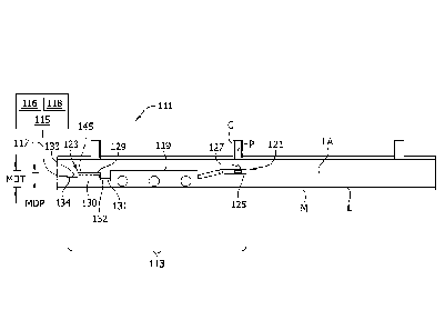
is connected to a plurality of lateral pipes C that drain from individual
users into the
main. In a water distribution system, a water main M can be coupled to a
plurality of
corporation stops C that provide connections to water service lines. Over the
life of a
sewer pipe system or a pressure pipe system, it may become necessary to
rehabilitate
or repair the main pipe M.
[0004] Referring to FIGS. 1B and 1C, one technique for rehabilitating a sewer
main comprises installing a cured-in-place pipe (CIPP) liner L along the main
pipe P. The
installed liner L initially blocks the connections to the lateral pipes C. So
after the liner L
has been put in place and installed, the fluid communication between the main
pipe M
and the service laterals C must be restored. As shown in FIG. 1C, holes are
formed in
the liner L at the service laterals C to restore fluid communication. For
example, fluid
communication can be established by a robot that travels through the interior
of the
main pipe M carrying a tool for forming holes in the liner L.
1
Date Recue/Date Received 2022-02-11
[0005]A conventional sequence of steps for rehabilitating a water main M under
pressure is illustrated schematically in FIGS. 1B'-1D'. Before positioning the
liner L in the
main pipe M, the openings to the corporation stops C are sealed with plugs P
(FIG. 1B).
The plugs P comprise fittings that are installed in the corporation stops C
from within
the main pipe M. Subsequently, a CIPP liner is installed in the main pipe M
(FIG. 1C).
The plugs P prevent resin in the liner L from entering the corporation stops C
as the liner
is pressed outwardly against the wall of the main pipe M and cured. After
installation of
the liner L is complete, holes are formed in the liner and portions of the
plugs P are
removed to restore fluid communication between the rehabilitated main pipe M
and the
corporation stops C. For example, fluid communication can be established by a
robot
that travels through the interior of the main pipe M carrying a tool for
forming holes in
the liner L.
[0006]This disclosure pertains to improvements in the devices, systems, and
methods used to form holes in a liner L for restoring fluid communication
between a
main pipe M and its branch conduits C. An exemplary application for the
devices,
systems, and methods described herein is restoring fluid communication between
a
sewer main M and its lateral conduits C as shown in FIGS. 1B and 1C. In
addition, the
devices systems and methods of the present disclosure are suitable for us in
restoring
fluid communication between a water main M or other pressure pipe and its
corporation
stops C or other service connections, as shown in FIGS. 1B'-1D'.
[0007]
SUMMARY
[0008] In one aspect, a mobile system for pipe rehabilitation comprises a
tractor configured for moving along a main pipe. A cutter is supported by the
tractor for
movement with the tractor along the main pipe. The cutter comprises a cutting
shaft
configured to mount a cutting bit and an electrical motor configured to drive
rotation of
the cutting shaft about a rotational axis such that the cutting shaft can
rotate the
cutting bit to remove a blockage from a branch conduit connected to the main
pipe. A
power management system is in electrical communication with at least the
cutter. The
2
Date Recue/Date Received 2022-02-11
power management system comprises a supercapacitor module including at least
one
supercapacitor. The power management system is configured to selectively power
the
electrical motor to drive rotation of the cutting shaft about a rotational
axis by
discharging current from the supercapacitor module to the cutter.
[0009] In another aspect, a power management system provides electrical
power to a mobile system configured for pipe rehabilitation. The mobile system
comprises a tractor and a cutter. The power management system comprises a
housing.
a first electrical coupling on the housing is configured to electrically
connect the power
management system to an umbilical cord carrying an input current. A second
electrical
coupling on the housing is configured to couple to the mobile system for
providing a
drive current to at least the cutter of the mobile system. A supercapacitor
module is
received in the housing. The supercapacitor module includes at least one
supercapacitor. The power management system is configured to charge the
supercapacitor module with the input current and selectively power the cutter
by
discharging current from the supercapacitor module to the cutter.
[0010] In another aspect, a mobile system for pipe rehabilitation comprises a
tractor configured for moving along a main pipe. A cutter is supported by the
tractor for
movement with the tractor along the main pipe. The cutter comprises a cutting
shaft
configured to mount a cutting bit and an electrical motor configured to drive
rotation of
the cutting shaft about a rotational axis such that the cutting bit when
mounted on the
cutting shaft can remove a blockage from a branch conduit connected to the
main pipe.
A power management system is in electrical communication with at least the
cutter.
The power management system is configured to connect to a direct current power
source that provides an input current having a voltage of less than 60V and to
power the
electrical motor from said input current.
[0011]Other aspects and features will be apparent hereinafter.
BRIEF DESCRIPTION OF THE DRAWINGS
[0012] FIG. 1A is a schematic illustration of a main pipe and branch conduit;
[0013] FIG. 1B is a schematic illustration of a sewer main lined with a CIPP
liner;
3
Date Recue/Date Received 2022-02-11
[0014] FIG. 1C is a schematic illustration of fluid communication between the
sewer main and a lateral pipe being restored after the sewer main is lined
with the liner;
[0015] FIG. 1B' is a schematic illustration of a corporation stop connected to
a
water main plugged by a plug;
[0016] FIG. 1C' is a schematic illustration of the water main of FIG. 1B'
lined by a
CIPP liner;
[0017] FIG. 1D' is a schematic illustration of the fluid communication between
the
water main and the corporation stop being restored after the corporation stop
has been
plugged and the main pipe has been lined;
[0018] FIG. 2 is a schematic illustration of a pipe rehabilitation system
being used
to remove a portion of a plug after a main pipe is lined with a CIPP liner;
[0019] FIG. 3 is a photograph of a power management system of the pipe
rehabilitation system coupled to a tractor of the pipe rehabilitation system;
[0020] FIG. 4 is a schematic diagram of the power management system; and
[0021] FIG. 5 is a schematic block diagram of the power management system.
DETAILED DESCRIPTION
[0022] U.S. Patent Application Publication No. 2020/0173599, which is hereby
incorporated by reference in its entirety, describes an exemplary system and
method for
rehabilitating host pipes that are connected to branch conduits, e.g.,
corporation stops.
In particular, U.S. Patent Application Publication No. 2020/0173599 discloses
an
exemplary cutting tool 1060 which may be used to restore fluid communication
between a main pipe and branch conduit after the main pipe has been lined with
a CIPP
liner. Cutting tools of the type disclosed in U.S. Patent Application
Publication No.
2020/0173599 are known to either run on an electrical motor or a pneumatic
drive.
[0023] In conventional systems for rehabilitating pipes of the type disclosed
in
U.S. Patent Application Publication No. 2020/0173599, electrical power and/or
compressed air is delivered directly to components of the robotic system
inside the
pipe via an umbilical cord that caries power from a source (e.g., a gas-
powered
generator, an air compressor) located outside the pipe. The inventors have
recognized a
4
Date Recue/Date Received 2022-02-11
need to improve the way that power is delivered over an umbilical cord to
robotic
systems inside a pipe. More particularly, the inventors have recognized that
cutting
tools of the type disclosed in U.S. Patent Application Publication No.
2020/0173599
require substantial power to remove portions of the liner L (and, in some
cases, the
plugs P) for restoring fluid communication between a main pipe M and its
branch
conduits C. Conventional electrical cutting tools require a dedicated high
voltage (e.g.,
230 V) electrical line along the umbilical cord to provide enough electrical
power to
prevent the tool from stalling during use. In the typical configuration, a
very heavy
Siamese cable is used with a dedicated electrical line for the cutting tool.
This high
voltage along the umbilical cord creates an electrical shock hazard at the
worksite, and
furthermore, the heavy Siamese cable can be difficult for the robot system to
maneuver
through the main pipe M. Similarly, when compressed air is used to power a
cutting tool,
the robotic system requires a large, heavy umbilical cord that can be
difficult to
maneuver through the main pipe. Furthermore, the inventors believe that
pneumatic
cutting tools are less efficient than electrical cutting tools.
[0024] Referring to FIG. 2, an exemplary embodiment of a pipe rehabilitation
system in the scope of the present disclosure is generally indicated at
reference
number 111. The pipe rehabilitation system 111 comprises a mobile system 113
for
use inside the main pipe M and a stationary control skid 115 located outside
of the pipe.
An umbilical cord 117 connects the mobile system 113 to the control skid 115.
The
entire mobile system 113 is movable inside the pipe M and relative to the
control skid
115. In the illustrated embodiment, the control skid 115 comprises one or more
power
sources, such as an electrical power source (e.g., a gas-powered electric
generator) 116
and an air compressor 118. The umbilical cord 117 operatively connects the
power
source(s) to the mobile system 113.
[0025] The mobile system 113 generally comprises a tractor 119 configured for
moving along a main pipe, an electric cutter 121 (broadly, cutting tool)
supported by the
tractor for movement with the tractor along the main pipe, and a power
management
system 123 in electrical communication with at least the cutter. It will be
appreciated
that the electric cutter 121 may be interchangeable with other robotic tools
as disclosed
Date Recue/Date Received 2022-02-11
in U.S. Patent Application Publication No. 2020/0173599. An exemplary
embodiment of
the tractor 119 (including associated drive mechanisms, tool positioning
mechanisms,
and pipe visualization systems) is described in further detail in U.S. Patent
Application
Publication No. 2020/0173599. The cutter 121 generally comprises a cutting
shaft (not
shown) configured to mount a cutting bit 127, and an electrical motor 125
configured to
drive rotation of the cutting shaft about a rotational axis such that the
cutting shaft can
rotate the cutting bit to remove a blockage from a branch conduit C connected
to the
main pipe M. In particular, the cutter 121 may be used in substantially the
same manner
as the cutting tool 24 of U.S. Patent Application Publication No. 2020/0173599
to
remove portions of a liner L (and in some cases portions of a plug P) from a
junction
between a branch conduit C and a main pipe M to restore fluid communication
between
the branch conduit and the main pipe after the main pipe is lined with the
liner.
[0026] In general, the power management system 123 is configured to store
electrical power delivered from the power source 115 to the mobile system 113
over the
umbilical cord 117 in an electrical storage device 129 and selectively
discharge the
stored power to the cutter 121 when used to remove a blockage from a branch
conduit.
In one or more embodiments, the power management system is configure to
communicate with the power source 115 and the mobile system 113 over a CAN
communication bus. Hence, the power management system 123 suitably comprises a
CAN bus isolator. In an exemplary embodiment, the power management system 123
is
configured to communicate with the power source 115 via a first CAN bus and is
configured to communicate with the mobile system 113 via a second CAN bus.
[0027]The power management system is configured to connect to a direct
current power source 116 that provides an input current having a voltage of
less than
60V and to power the electrical motor 125 using this input current. In an
exemplary
embodiment, the input current has a voltage of less than 60V (e.g., about
54V). As those
skilled in the art will appreciate, this minimizes the perceived safety risk
of the electrical
current passing along the umbilical cord. In addition to powering the cutter
121 via
power from the power source 116, the illustrated power management system 123
is
also configured to power other electrical components supported on the tractor
119,
6
Date Recue/Date Received 2022-02-11
including a tractor drive system, a tool positioning system, and an imaging
system
associated with the tractor. More particularly, the power management system
123 is
configured to power the other electrical components separately from any
discharge of
current from the power storage device 129. Further, the power management
system
123 is configured to power the electrical components without interruption,
while
discharging current from the power storage device 129 to power the cutter 125.
In the
illustrated embodiment, the umbilical cord 117 comprises a single power line
that
supplies power to both the cutter 121 and the other electrical components of
the tractor
119.
[0028] The power management system 123 comprises a housing 130 configured
to be supported on the tractor 119 for movement with the tractor along the
main pipe
M. In the illustrated embodiment, the power management system 123 is connected
in
series between the umbilical cord 117 and the tractor 119. Further, the mobile
system
113 is adapted so that the tractor 119 can be used without the power
management
system 123 when the cutter 121 is not in use. The tractor 113 has a front end
portion
and a rear end portion spaced apart along a longitudinal axis LA. Referring to
FIGS. 2
and 3, the tractor 113 comprises a first electrical coupling 131 is on the
rear end
portion. The first electrical coupling 131 (broadly, an input coupling) is
configured to
couple directly to the tractor 119 for supplying the input current to the
mobile system
113. The power management system 123 comprises a second electrical coupling
132
(broadly, an output coupling) configured to couple to the first electrical
coupling 131
and a third electrical coupling 133 (broadly, another input coupling)
configured to
couple to the umbilical cord 117. The input couplings 131, 133 on both the
tractor 119
and the power management system 123 are essentially the same, and the output
coupling 132 of the power management system is essentially the same as an
outlet
coupling 134 on the end of the umbilical cord 117. In an exemplary embodiment,
connecting the second coupling 132 to the first coupling 131 both (1)
establishes an
electrical connection between the power management system 123 and the tractor
119
and (2) mounts the power management system on the tractor such that the power
management system is supported on the tractor for movement with the tractor
along
7
Date Recue/Date Received 2022-02-11
the main pipe M. For example, in the illustrated embodiment, connecting the
first and
second couplings 131, 132 supports the power management system housing in
cantilevered relationship with the tractor 119. In the illustrated embodiment,
in addition
to the electrical coupling 132, a separate cable (visible in FIG. 3) extends
from the
power management system 123 to the cutting tool 121 for powering the cutting
tool. In
other words, there are separate electrical pathways for providing current from
the power
management system 123 to the tractor 113 and for providing current from the
power
management system 123 to the cutting tool 121.
[0029] The illustrated power management system housing 130 is generally
cylindrical. The housing 130 has a maximum cross sectional dimension MDP
(e.g., an
outer diameter) in a plane perpendicular to the longitudinal axis LA. As shown
in FIG, 2,
the tractor 113 likewise has a maximum tractor cross-sectional dimension MDT
in a
plane perpendicular to the longitudinal axis LA. The maximum tractor cross-
sectional
dimension MDT is suitably greater than the maximum housing cross-sectional
dimension MDP. This allows the power management system 123 to be trailered by
the
tractor 113 through the main pipe M substantially without interfering with the
main pipe.
[0030] Referring to FIGS. 4 and 5, in the illustrated embodiment, the
electrical
storage device 129 of the power management system 123 comprises a
supercapacitor
module having one or more supercapacitors 141 received in the housing 130. The
illustrated supercapacitor module 129 comprises a plurality of supercapacitors
141
electrically connected to one another in series. For example, in one or more
embodiments, the supercapacitor module 129 comprises at least ten
supercapacitors
141. In an exemplary embodiment, the supercapacitor module 129 comprises
eighteen
supercapacitors. Each supercapacitor has a discharge voltage of at least 1.0
V. For
example, in one or more embodiments, each supercapacitor 141 has a discharge
voltage of 3 V. Suitably, the entire supercapacitor module 129 has a capacity
of at least
50F (e.g., a total capacity of about 100F). The power management system 123
comprises a dedicated charge controller 142 (FIG. 5) for each of the plurality
of
supercapacitors 141. Each dedicated charge controller 142 ("Commended positive
balancing module") is configured to monitor a charge of the respective
supercapacitor
8
Date Recue/Date Received 2022-02-11
141 and the charge controllers 142 collectively are configured to balance the
charges of
the supercapacitors to prevent overcharging of any individual capacitor. In
one or more
embodiments, the charge controllers 142 are of the resistor type. Moreover,
each
charge controller 142 includes a maximum point tracking feature to constantly
monitor
and adjust the current draw to achieve maximum energy.
[0031]The power management system 123 further comprises a single DC-to-DC
converter 145 connected between the umbilical cord 117 and the supercapacitors
129.
In the illustrated embodiment, the converter 145 comprises a buck-boost
converter
configured to selectively step-down or step-up the voltage of the input
current. When
the power management system 123 is called upon to deliver power to electrical
components other than the cutter 121, the converter 145 operates in a buck
mode (e.g.,
a step-down mode) to step down the voltage of the input current. For example,
in the
embodiment shown in FIG. 5, the converter 145 is configured to step down the
input
voltage of 55 V to an output voltage of 48 V DC. The lower-voltage output
current flows
through the supercapacitor module 129 to charge the supercapacitors 141 when
they
are not being discharged to power the cutter 121.
[0032]The cutter 121 comprises a cutter driver 143 (brushless direct current
driver or "BLDC Driver") that is configured to control the delivery of power
from the
power management system 123 to the cutter motor 125. In one or more
embodiments
the cutter driver 143 and the converter 145 are integrated into the same
printed circuit
board. Suitably, the CAN bus isolator and CAN bus transceivers for the first
and second
CAN busses used to communicate with the power source 115 and the mobile system
113 can likewise be integrated into the same printed circuit board with the
cutter driver
143 and the converter 145. It will be understood, however, that separate
printed circuit
boards can also be used for the components without departing from the scope of
the
disclosure. The cutter driver 143 is connected to the supercapacitor module
129 such
that the supercapacitor module discharges current to the cutter driver 143. In
an
exemplary embodiment, a bleeder resistor (not shown) is connected in parallel
with the
output of the supercapacitor module 129 to the cutter driver to quickly
discharge the
supercapacitor module system after power off. In the illustrated embodiment,
when the
9
Date Recue/Date Received 2022-02-11
cutter driver 143 calls for power to the cutter 121, the supercapacitor module
129
discharges current to the cutter driver 143 in an amount sufficient to drive
the cutter
motor 125 for removing a blockage without stalling. Whenever current is being
discharged from the supercapacitor module 129, there is a substantial drop in
the
voltage of the input current. The converter 145 is configured address this
drop in
voltage by operating in a buck boost mode to step up the voltage of the input
current.
This allows other electrical components to be run without interruption, even
when the
cutter motor 125 is drawing the substantial current required to remove a
blockage from
a branch conduit C. For example, a camera (not shown) positioned for viewing
within
the pipe would not have its video transmission interrupted during cutting.
[0033] As can be seen, the above-described power management system enables
a pipe rehabilitation system to run an efficient electrical cutting tool
without requiring a
hazardous high voltage line or heavy Siamese cable.
[0034] When introducing elements of the present disclosure or the preferred
embodiment(s) thereof, the articles "a", "an", "the" and "said" are intended
to mean that
there are one or more of the elements. The terms "comprising", "including" and
"having"
are intended to be inclusive and mean that there may be additional elements
other than
the listed elements.
[0035] In view of the above, it will be seen that the several objects of the
disclosure are achieved and other advantageous results attained.
[0036] As various changes could be made in the above products and methods
without departing from the scope of the disclosure, it is intended that all
matter
contained in the above description shall be interpreted as illustrative and
not in a
limiting sense.
Date Recue/Date Received 2022-02-11