Note : Les descriptions sont présentées dans la langue officielle dans laquelle elles ont été soumises.
WO 2021/040901
PCT/US2020/042213
ARTICLE CARRIER AND BLANK THERFOR
TECHNICAL FIELD
The present invention relates to article carriers and to blanks for forming
the same. More
specifically, but not exclusively, the invention relates to a wraparound
carrier having a carrying
handle_ Aspects of the invention relate to an article retention structure
including an
engagement device for securing an upper end of an article. Additionally or
alternatively the
invention relates to a wraparound carrier having a dispenser feature for
gaining access to the
contents of the carrier.
BACKGROUND
In the field of packaging it is known to provide cartons or article carriers
for carrying multiple
articles. Cartons are well known in the art and are useful for enabling
consumers to transport,
store and access a group of articles for consumption. For cost and
environmental
considerations, such cartons or carriers need to be formed from as little
material as possible
and cause as little wastage in the materials from which they are formed as
possible. Further
considerations are the strength of the carton and its suitability for holding
and transporting
large weights of articles. It is desirable that the carton comprises a
carrying handle sufficiently
strong enough to bear the bad of the carton and its contents.
It is desirable that the articles held within a carton are securely held and
protected during
transportation_ It is also desirable that the articles within a carton can be
readily accessed.
The present invention seeks to provide an improvement in the field of cartons,
typically formed
from paperboard or the like.
SUMMARY
A first aspect of the invention provides an article carrier for packaging at
least two articles each
having a recess. The article carrier comprises a plurality of panels forming a
tubular structure
for surrounding the at least two articles and a pair of article retention
devices each comprising
a flap for engaging a recess of a respective one of said at least two articles
to inhibit movement
of the articles within the tubular structure. The flaps are hingedly connected
by a respective
hinged connection to one of the plurality of panels in opposition to each
other. The article
carrier comprises a pair of handle openings defined in said one of the
plurality of panels. The
handle openings and the flaps define a handle in said one of the plurality of
panels. The handle
is coupled or connected to said one of the plurality of panels by four arms.
Each arm is
- 1 -
CA 03149524 2022-2-25
WO 2021/040901
PCT/US2020/042213
provided by a region of said one of the plurality of panels disposed or
defined between one of
the handle openings and one of the flaps.
Optionally, the tubular structure is at least partially open at each end and a
tubular axis is
defined between said ends and wherein the hinged connection between the flaps
and the one
of the plurality of panels is parallel to the tubular axis.
Optionally, the tubular structure is at least partially open at each end and a
tubular axis is
defined between said ends and wherein the hinged connection between the flaps
and the one
of the plurality of panels is oblique to the tubular axis.
Optionally, said one of the plurality of panels is a top panel.
Optionally, the flaps are hingedly connected to said one of the plurality of
panels by a hinged
connection in the form of a first fold line.
Optionally, the plurality of panels include a pair of opposed side walls and
the flaps fold
towards a respective one of the opposed side walls.
A second aspect of the invention provides an article carrier for packaging one
or more articles
each having a recess, the article carrier comprising a plurality of panels
forming a tubular
structure for surrounding the one or more articles and an article retention
device for engaging
a recess of one of the one or more articles to inhibit movement of said
article within the tubular
structure, wherein the article retention device comprises a flap hingedly
connected to one of
the plurality of panels, the article carder further comprises a dispenser
feature having an
access panel, and wherein the flap is hingedly connected to the access panel
so as to provide
a tear initiation device for the dispenser.
Optionally, the access panel is defined at an end of the article carrier, the
access panel is
defined in part by a free end edge of the article carrier and in part by a
severable line extending
from the flap.
Optionally, the access panel is defined in an intermediate portion of the
article carrier, the
access panel is defined at least in part by a pair of severable lines
extending from the flap, the
pair of severable lines are spaced apart from each end of the article carrier.
- 2 -
CA 03149524 2022-2-25
WO 20211040901
PCT/US2020/042213
A third aspect of the invention provides an article carrier for packaging one
or more articles
each having a recess, the article carrier comprising a plurality of panels
forming a tubular
structure for surrounding the one or more articles and an article retention
device for engaging
a recess of one of the one or more articles to inhibit movement of said
article within the tubular
structure, the article retention device comprising a flap hingedly connected
by a hinged
connection to one of the plurality of panels, the flap comprising a hinged
edge defined by the
hinged connection and a free edge, wherein the free edge extends from a first
end of the
hinged connection to a second end of the hinged connection, and wherein the
free edge is
arcuate or curved across or along its entire extent.
Optionally, the hinged edge of the flap is disposed closer to one of a pair of
opposed side walls
than the free edge in an unfolded condition.
Optionally, the flap, in an operative condition, is reverse folded into face
to face relationship
with an inner surface of the panel to which it is hinged, when the flap is in
the operative position
the free edge of the flap is disposed closer to one of a pair of opposed side
walls than the
hinged edge.
Optionally, the hinged connection is oriented non-parallel to an open end of
the tubular
structure.
Optionally, the hinged connection is obliquely oriented to an open end of the
tubular structure.
Optionally, the hinged connection is perpendicularly oriented with respect to
an open end of
the tubular structure.
Optionally, the article retention device is located in a recess defined in an
end of said one of
the plurality of panels.
Optionally, the top panel comprises at least one recessed end edge to which
article retention
device is hingedly connected.
Optionally, the flap partially defines the at least one recessed end edge of
the top panel in an
unfolded condition.
- 3 -
CA 03149524 2022-2-25
WO 2021/040901
PCT/US2020/042213
Optionally, the article carrier comprises a pair of article retention devices
at an end of said one
of the plurality of panels, and wherein the pair of article retention devices
are spaced apart
from each other by a recess struck from or defined in an end edge of the top
panel.
Optionally, the pair of article retention devices are hingedly connected to
the top panel by a
respective fold line, said fold lines being divergently arranged with respect
to each other.
Optionally, the flap is folded inwardly about a hinged connection to said one
of the plurality of
panels more than 90 degrees so as to be substantially in face to face
relationship with the
panel to which it is hinged.
Optionally, the article retention device comprises a fold line defined in the
flap and forming a
keel for increasing the security of the article within the article carrier.
Optionally, the fold line defines in part a wing tab, the wing tab coupled to
the said one of the
plurality of panels only through its hinged connection to the flap.
Optionally, the fold line is arranged to converge at an end of the hinged
connection to form a
vertex, and wherein a cutaway separates the wing tab from the said one of the
plurality of
panels, the cutaway intersects with the vertex between the hinged connection
and fold line.
Optionally, the article carrier is of the wrap-around type, comprising a
composite wall formed
from two panels secured together.
Optionally, the composite wall is a bottom wall of the tubular structure.
Optionally, the flap of the article retention device is contained entirely
within the footprint of
said one of the plurality of panels.
Optionally, the flaps of the pair of article retention devices are contained
entirely within the
footprint of the top panel.
A fourth aspect of the invention provides a blank for forrning an article
carrier, the blank
comprising a plurality of panels for forming a tubular structure for
surrounding at least two
articles each having a recess, the blank comprising a pair of article
retention devices each
comprising a flap for engaging a recess of a respective one of said at least
two articles to
inhibit movement of the articles within the tubular structure, wherein the
flaps are hingedly
- 4 -
CA 03149524 2022-2-25
WO 20211040901
PCT/US2020/042213
connected by a respective hinged connection to one of the plurality of panels
in opposition to
each other, the blank comprising a pair of handle openings defined in said one
of the plurality
of panels, the handle openings and the flaps define a handle in said one of
the plurality of
panels, the handle is coupled or connected to said one of the plurality of
panels by four arms,
each arm is provided by a region of said one of the plurality of panels
disposed or defined
between one of the handle openings and one of the flaps.
Optionally, the tubular structure, in a setup condition, is at least partially
open at each end and
a tubular axis is defined between said ends and wherein the hinged connection
between the
flaps and the one of the plurality of panels is parallel to the tubular axis.
Optionally, the tubular structure, in a setup condition, is at least partially
open at each end and
a tubular axis is defined between said ends and wherein the hinged connection
between the
flaps and the one of the plurality of panels is oblique to the tubular axis.
Optionally, the flaps are hingedly connected to said one of the plurality of
panels by a hinged
connection in the form of a first fold line.
Optionally, the plurality of panels include a pair of opposed side walls
hingedly connected to
a top panel along hinged edges thereof and the flaps fold towards a respective
one of the
hinged edges.
A fifth aspect of the invention provides a blank for forming an article
carrier, the blank
comprising a plurality of panels forming a tubular structure for surrounding
one or more articles
having a recess and an article retention device for engaging the recess of one
of the one or
more articles to inhibit movement of said article within the tubular
structure, wherein the article
retention device comprises a flap hingedly connected to one of the plurality
of panels, the
blank further comprises a dispenser feature having an access panel, and
wherein the flap is
hingedly connected to the access panel so as to provide a tear initiation
device for the
dispenser.
A sixth aspect of the invention provides a blank for forming an article
carrier, the blank
comprising a plurality of panels forming a tubular structure for surrounding
one or more articles
having a recess and an article retention device for engaging the recess of the
one of one or
more articles to inhibit movement of said article within the tubular
structure, the article retention
device comprising a flap hingedly connected by a hinged connection to one of
the plurality of
panels, the flap comprising a hinged edge defined by the hinged connection and
a free edge,
- 5 -
CA 03149524 2022-2-25
WO 2021/040901
PCT/US2020/042213
wherein the free edge extends from a first end of the hinged connection to a
second end of
the hinged connection, and wherein the free edge is arcuate or curved across
or along its
entire extent.
Within the scope of this application it is envisaged or intended that the
various aspects,
embodiments, examples, features and alternatives set out in the preceding
paragraphs, in the
claims and/or in the following description and drawings may be considered or
taken
independently or in any combination thereof.
Features or elements described in connection with, or relation to, one
embodiment are
applicable to all embodiments unless there is an incompatibility of features.
One or more
features or elements from one embodiment may be incorporated into, or combined
with, any
of the other embodiments disclosed herein, said features or elements extracted
from said one
embodiment may be included in addition to, or in replacement of one or more
features or
elements of said other embodiment_
A feature, or combination of features, of an embodiment disclosed herein may
be extracted in
isolation from other features of that embodiment. Alternatively, a feature, or
combination of
features, of an embodiment may be omitted from that embodiment.
BRIEF DESCRIPTION OF THE DRAWINGS
Embodiments of the invention will now be described with reference to the
accompanying
drawings, in which:
Figure 1 is a plan view from above of a blank for forming an article carrier
according to
embodiments of the disclosure;
Figure 1B is an enlarged view of a portion of the blank of Figure 1;
Figure 2 is a perspective view of an article carrier formed from the blank of
Figure 1;
Figure 3 is a perspective view of the article carrier of Figure 2 showing a
dispenser in a
deployed condition; and
Figure 4 is a plan view from above of a blank for forming an article carrier
according to
further embodiments of the disclosure.
DETAILED DESCRIPTION OF EMBODIMENTS
Detailed descriptions of specific embodiments of the package, blanks and
article carriers are
disclosed herein. It will be understood that the disclosed embodiments are
merely examples
of the way in which certain aspects of the invention can be implemented and do
not represent
an exhaustive list of all of the ways the invention may be embodied. As used
herein, the word
- 6 -
CA 03149524 2022-2-25
WO 2021/040901
PCT/US2020/042213
"exemplary" is used expansively to refer to embodiments that serve as
illustrations,
specimens, models, or patterns. Indeed, it will be understood that the
packages, blanks and
article carriers described herein may be embodied in various and alternative
forms. The
Figures are not necessarily to scale and some features may be exaggerated or
minimised to
show details of particular components. Well-known components, materials or
methods are not
necessarily described in great detail in order to avoid obscuring the present
disclosure. Any
specific structural and functional details disclosed herein are not to be
interpreted as limiting,
but merely as a basis for the claims and as a representative basis for
teaching one skilled in
the art to variously employ the invention.
Referring to Figure 1, there is shown a plan view of a blank 10 capable of
forming a carton or
carrier 90, as shown in Figure 2, for containing and carrying a group of
primary products such
as, but not limited to, beverage cans, hereinafter referred to as articles B,
as shown in Figure
2. The blank 10 can be assembled to forrn a secondary package for packaging at
least one
primary product container or package.
Referring to Figure 4, there is shown a plan view of another blank 110 capable
of forming a
carton or carrier (not shown) for containing and carrying a group of primary
products such as,
but not limited to, beverage cans. The blank 110 can be assembled to form a
secondary
package for packaging at least one primary product container or package.
In the embodiments detailed herein, the terms "carton" and "carrier" refer,
for the non-limiting
purpose of illustrating the various features of the invention, to a container
90 for engaging and
carrying articles B. such as primary product containers B. It is contemplated
that the teachings
of the invention can be applied to various product containers B, which may or
may not be
tapered and/or cylindrical. Other exemplary containers include bottles (for
example metallic,
glass or plastics bottles), cans (for example aluminium cans), tins, cups,
pots, pouches,
packets and the like.
The blanks 10, 110 are formed from a sheet of suitable substrate. It is to be
understood that,
as used herein, the term "suitable substrate" includes all manner of foldable
sheet material
such as paperboard, corrugated board, cardboard, plastic, combinations
thereof, and the like.
It should be recognised that one or other numbers of blanks may be employed,
where suitable,
for example, to provide the carrier structure described in more detail below.
The packaging structures or carton 90 described herein may be formed from a
sheet material
such as paperboard. Typically, one surface of the sheet material may have
different
- 7 -
CA 03149524 2022-2-25
WO 2021/040901
PCT/US2020/042213
characteristics to the other surface. For example, the surface of the sheet
material that faces
outwardly from a finished package may be particularly smooth and may have a
coating such
as a clay coating or other surface treatment to provide good printability. The
surface of the
sheet material that faces inwardly may, on the other hand, be provided with no
coating or a
coating. If coated, the coating layer or treatment may provide properties such
as one or more
of tear-resistance, good glue-ability, heat sealability, or other desired
functional properties.
In the embodiments illustrated in Figures 1 and 4, the blanks 10, 110 are
configured to form a
carton or carrier 90 for packaging an exemplary arrangement of exemplary
articles B. In the
illustrated embodiments the arrangement is an m x n matrix or array, having
two rows (m=2)
and three columns (n=3): in the illustrated embodiments two rows of three
articles B are
provided, and the articles B are 330m1 beverage cans.
Alternatively, the blanks 10, 110 can be configured to form a carrier for
packaging other types,
number and size of articles B and/or for packaging articles B in a different
arrangement or
configuration for example, but not limited to, fully enclosed cartons or
basket carriers, the
articles B may be bottles or cans.
Turning to Figure 1, there is illustrated a blank 10 for forming an article
carrier 90 (see Figure
2) according to an embodiment of the disclosure. The blank 10 comprises a
plurality of main
panels 12, 14, 16, 18, 20, 22, 24, 26, 28 for forming a tubular structure. The
plurality of main
panels 12, 14, 16, 18, 20, 22, 24, 26, 28 comprises: a first base panel 12, a
first corner or
bevel panel 14, a first side panel 16, a second corner or bevel panel 18, a
top panel 20, a third
corner or bevel panel 22, a second side panel 24, a fourth corner or bevel
panel 26 and a
second base panel 28. The plurality of panels 12, 14, 16, 18, 20, 22, 24, 26,
28 may be
arranged in a linear series hinged one to the next by corresponding fold lines
13, 15, 17, 19,
21, 23, 25, 27.
In alternative embodiments, the first, second, third and fourth corner panels
14, 18, 22, 26
may be omitted.
Fold line 13 and fold line 27 optionally comprise cut lines or severance lines
(not shown) which
are collinear with the respective one of fold line 13 and fold line 27 so as
to interrupt said fold
line 13, 27 or be coincident therewith. Severance lines may provide shock
absorbing or
damping devices proximate the base of the carton 90.
- 8 -
CA 03149524 2022-2-25
WO 2021/040901
PCT/US2020/042213
The first and fourth corner panels 14, 26 may be considered to form lower
portions of the
respective one of the first or second side panels 16, 24, or alternatively
form part of the first or
second base panels 12, 28, to which they are hingedly connected.
The second and third comer panels 18, 22 may be considered to form upper
portions of the
respective one of the first or second side panels 16, 24, or alternatively
form part of the top
panel 20.
The blank 10 is foldable to form a package 90 as illustrated in Figures 3 and
4. The first and
second base panels 12, 28 are engageable with one another in an overlapping
relationship to
form a composite base wall 12/28 of the carton 90. The blank 10 may comprise a
complementary locking mechanism for securing the second base panel 28 to the
first base
panel 12. The second base panel 28 may comprise at least one first part F of
the
complementary locking mechanism. The first base panel 12 may comprise at least
one second
part M of the complementary locking mechanism. In the illustrated embodiment,
the second
base panel 28 comprises a plurality of female tabs F defining openings in the
second base
panel 28. The first base panel 12 comprises a plurality of male tabs M; and
the openings in
the second base panel 28 are configured to receive a respective one of the
male tabs M. The
female tabs F are arranged to be displaced out of the second base panel 28 to
form the
opening and to bear against the male tabs M when received therein. In some
embodiments
the complementary locking mechanism M/F may be omitted; and the first and
second base
panels 12, 28 may be secured to each other by other means such as but not
limited to
adhesive or staples.
The complementary locking mechanism illustrated and described is entirely
optional.
Optionally, the first and second base panels 12, 28 may comprise at least one
first aperture
Al. In the illustrated embodiment, each of the first and second base panels
12, 28 comprises
two first apertures Al. Optionally, the first and second base panels 12, 28
may comprise at
least one second aperture A2. In the illustrated embodiment, each of the first
and second base
panels 12, 28 comprises one second aperture A2. The first and second apertures
Al, A2 may
be employed to facilitate construction of the carton 90. A packaging machine
component may
engage with the first and second apertures Al, A2 to enable the plurality of
panels 12, 14, 16,
18, 20, 22, 24, 26, 28 to be tightened about a group of articles B. The first
and second
apertures Al, A2 may also be employed to facilitate alignment of the first and
second base
panels 12,28 with respect to each other or to align the first part F of the
complementary locking
mechanism with the second part M of the complementary locking mechanism.
- 9 -
CA 03149524 2022-2-25
WO 2021/040901
PCT/US2020/042213
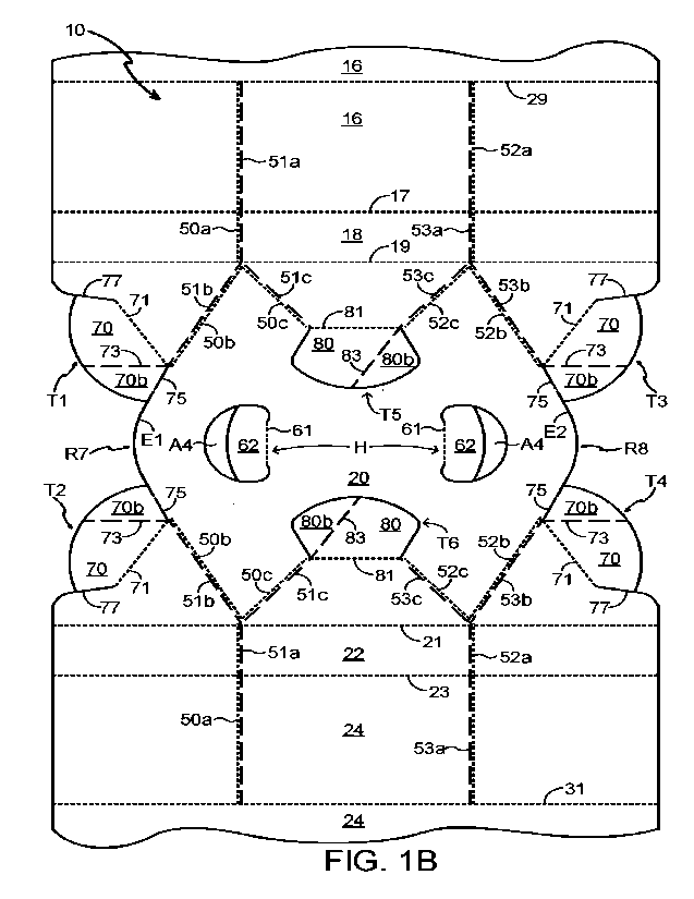
The blank 10 comprises at least one first article retention device or article
engagement
structure (also referred to herein as end article retention devices or article
engagement
structures) T1, T2, T3, T4 for engaging an upper end of the articles B. The
blank 10 illustrated
in Figures 1 and 1B comprises four first article engagement structures Ti, T2,
T3, T4.
Each of the first article engagement structures T1, T2, T3, T4 comprises a
flap 70 hingedly
connected to the top panel 20. A first and a second one of the first article
engagement
structures Ti, T2 each comprise a flap 70 hingedly connected to the top panel
20 to a first end
of the top panel 20. A third and a fourth one of the first article engagement
structures T3, T4
each comprise a flap 70 hingedly connected to the top panel 20 to a second end
of the top
panel 20.
The flaps 70 of the first and second first article engagement structures T1,
T2 are inset from
a first outer edge of the blank 10.
The first and second first article engagement structures T1, T2 may be inset
with respect to a
first end edge of the first or second side panels 14, 24.
The first and second first article engagement structures T1, T2 may be inset
with respect to
marginal edge portions of the top panel 20.
The flaps 70 of the first and second first article engagement structures T1,
T2 may be inset
from a first free end edge of the top panel 20.
The flaps 70 of the third and fourth first article engagement structures T3,
T4 are inset from a
second outer edge of the blank 10_
The third and fourth article first engagement structures T3, T4 may be inset
with respect to a
second end edge of the first or second side panels 14, 24.
The third and fourth first article engagement structures T3, T4 may be inset
with respect to
marginal edge portions of the top panel 20.
The flaps 70 of the third and fourth first article engagement structures T3,
T4 may be inset
from a second free end edge of the top panel 20.
- 10 -
CA 03149524 2022-2-25
WO 2021/040901
PCT/US2020/042213
The flaps 70 of the first article engagement structures T1, T2, T3, T4 do not
extend beyond
the footprint of the top panel 20. The flaps 70 of the first article
engagement structures T1, T2,
T3, T4 are contained entirely within the footprint of the top panel 20.
The flaps 70 do not extend beyond the ends of the top panel 20.
The flaps 70 of the first article engagement structures T1, T2, T3, T4 do not
extend beyond
edges of the blank 10 defined, at least in part, by the first and second side
panels 16, 24.
Marginal portions of the top panel 20 hingedly connected to each of the first
and second side
panels 16, 24, or second and third bevel panels 18, 22 when present, are equal
in length to
the first and second side panel 16, 24 (or second and third bevel panels 18,
22) and to the
bottom panels 12, 28 or at least portions of the bottom panels 12, 28; said at
least portions of
the bottom panels 12, 28 may be marginal portions each being hingedly to one
of the first and
second side panels 16, 24, or first and fourth bevel panels 14, 26 when
present.
A first recess R7 is provided in the first end of the top panel 20, the flaps
70 of the first and
second first article engagement structures Ti, T2 can be considered to be
located in the first
recess R7. The flaps 70 of the first and second first article engagement
structures Ti, T2
define in part the first recess R7 and when folded out of the plane of the top
panel 20 increase
the size of the first recess R7.
The first recess R7 is arranged to accommodate the entirety of the flaps 70
and wing tabs 70b
when present.
The first recess R7 is defined only in the top panel 20 and does not extend
into the first and
second side panel 16, 24 or second and third bevel panels 18, 22.
The flap 70 of the first one of the first article engagement structures Ti is
hingedly connected
to the top panel 20 by a hinged connection in the form of a fold line 71 which
is obliquely
oriented with respect to the fold line 19 hinging the top panel 20 to the
second corner panel
18. The fold line 71 is spaced apart from a first end edge of one of the
marginal portions of the
top panel 20.
The flap 70 of the second one of the first article engagement structures T2 is
hingedly
connected to the top panel 20 by a hinged connection in the form of a fold
line 71 which is
obliquely oriented with respect to the fold line 21 hinging the top panel 20
to the third corner
- 11 -
CA 03149524 2022-2-25
WO 2021/040901
PCT/US2020/042213
panel 22. The fold line 71 is spaced apart from a first end edge of the other
one of the marginal
portions of the top panel 20.
The fold line 71 hinging the flap 70 of the first one of the first article
engagement structures T1
to the top panel 20 is divergently arranged with respect to the fold line 71
hinging the flap 70
of the second one of the first article engagement structures T2 to the top
panel 20. The fold
line 71 hinging the flap 70 of the first one of the first article engagement
structures T1 to the
top panel 20 and the fold line 71 hinging the flap 70 of the second one of the
first article
engagement structures T2 to the top panel 20 define an angle therebetween the
angle may
be less than 120 and in some embodiments may be around 110 . The angle may be
greater
than 80 and may be greater than 90 .
The fold line 71 hinging the flap 70 of the first one of the first article
engagement structures Ti
to the top panel 20 and the fold line 71 hinging the flap 70 of the second one
of the first article
engagement structures T2 to the top panel 20 are arranged to diverge towards
the first end of
the top panel 20.
The fold line 71 hinging the flap 70 of the first one of the first article
engagement structures Ti
to the top panel 20 and the fold line 71 hinging the flap 70 of the second one
of the first article
engagement structures T2 to the top panel 20 are arranged to converge towards
the centre or
middle of the top panel 20.
In this way the flap 70 of the first one of the first article engagement
structures T1 and the flap
70 of the second one of the first article engagement structures T2 fold away
from each other.
A second recess R8 is provided in the second end of the top panel 20, the
flaps 70 of the third
and fourth first article engagement structures T3, T4 can be considered to be
located in the
second recess R8. The flaps 70 of the third and fourth first article
engagement structures T3,
T4 define in part the second recess R8 and when folded out of the plane of the
top panel 20
increase the size of the second recess R8.
The second recess R8 is defined only in the top panel 20 and does not extend
into the first
and second side panel 16, 24 or second and third bevel panels 18, 22.
The second recess R8 is arranged to accommodate the entirety of the flaps 70
and wing tabs
70b when present.
- 12 -
CA 03149524 2022-2-25
WO 20211040901
PCT/US2020/042213
The flap 70 of the third one of the first article engagement structures T3 is
hingedly connected
to the top panel 20 by a hinged connection in the form of a fold line 71 which
is obliquely
oriented with respect to the fold line 19 hinging the top panel 20 to the
second corner panel
18. The fold line 71 is spaced apart from a second end edge of said one of the
marginal
portions of the top panel 20.
The flap 70 of the fourth one of the first article engagement structures T4 is
hingedly connected
to the top panel 20 by a hinged connection in the form of a fold line 71 which
is obliquely
oriented with respect to the fold line 21 hinging the top panel 20 to the
third comer panel 22.
The fold line 71 is spaced apart from a second end edge of said other one of
the marginal
portions of the top panel 20.
The fold line 71 hinging the flap 70 of the third one of the first article
engagement structures
T3 to the top panel 20 is divergently arranged with respect to the fold line
71 hinging the flap
70 of the fourth one of the first article engagement structures T4 to the top
panel 20.
The fold line 71 hinging the flap 70 of the third one of the first article
engagement structures
T3 to the top panel 20 and the fold line 71 hinging the flap 70 of the fourth
one of the first
article engagement structures T4 to the top panel 20 are arranged to diverge
towards the first
end of the top panel 20.
The fold line 71 hinging the flap 70 of the third one of the first article
engagement structures
T3 to the top panel 20 and the fold line 71 hinging the flap 70 of the fourth
one of the first
article engagement structures T4 to the top panel 20 are arranged to converge
towards the
centre or middle of the top panel 20.
In the blank form the flaps 70 define in part free end edges of the top panel
20. The edge
portions of the top panel 20 defined by the flaps 70 are arcuate or
curvilinear in shape.
The flap 70 of each of the first, second, third and fourth first article
engagement structures T1,
T2, T3, T4 is partially defined by at least one cut 75, 77 which separates
that flap 70 from the
top panel 20.
A first cut 75 extends from a first or inner end of the fold line 71 to the
respective one of the
first and second recesses R7, R8.
- 13 -
CA 03149524 2022-2-25
WO 2021/040901
PCT/US2020/042213
A second cut 77 is disposed between the flap 70 and a respective one of the
adjacently
disposed fold lines 19, 21 hinging the top panel 20 to the first or second
side panel 16, 24 (or
second or third bevel panel 18, 22 when present).
The first and second cut lines 75, 77 are divergently arranged with respect to
each other.
A first end edge E1/75 of the top panel 20 which extends between the fold
lines 71 of the flaps
70 of the first and second first article engagement structures Ti, T2 is non-
linear. It may be
arcuate or curvilinear. The end edge El /75 is convex such that it can be
considered to define
a portion of the top panel 20 protruding into the first recess R7.
At least part of the first end edge El of the top panel 20 extending between
the flaps 70 of the
first and second first article engagement structures Ti, T2 is disposed at a
position further
from the centre or middle of the top panel 20 than the inner ends 71a of the
fold lines 71 of
those flaps 70.
A second end edge E2/75 of the top panel 20 which extends between the fold
lines 71 of the
flaps 70 of the third and fourth first article engagement structures T3, T4 is
non-linear. It may
be arcuate or curvilinear. The end edge E2/75 is convex such that it can be
considered to
define a portion of the top panel 20 protruding into the second recess R8.
At least part of the second end edge E2 of the top panel 20 extending between
the flaps 70 of
the third and fourth first article engagement structures T3, T4 is disposed at
a position further
from the centre or middle of the top panel 20 than the inner ends 71a of the
fold lines 71 of
those flaps 70.
Each of the first article engagement structures Ti, T2, T3, T4 comprises a
wing tab 70b
hingedly connected to the flap 70 by a hinged connection in the form of a fold
line 73.
The fold line 73 may form a keel when the first article engagement structures
T1, T2, T3, T4
are in use engaging an article B. The keel may form a ridge to increase
stability or rigidity of
the first article engagement structures T1, T2, T3, T4. The flap 70 and the
wing tab 70b may
adopt a non-coplanar arrangement, for example, but not limited to, when an
article moves
outwardly through the open end of the tubular structure forming the article
carder B. The wing
tab 70b may fold with respect to the flap 70.
- 14 -
CA 03149524 2022-2-25
WO 20211040901
PCT/US2020/042213
The fold line 73 may be obliquely oriented with respect to the fold line 71
and may define an
acute angle therebetween.
The wing tabs 70b are connected only to the flaps 70 and are free from
connection to the top
panel 20 other than the indirect connection by virtue of being coupled to the
flaps 70, that is
to say there is no direct connection of the wing tabs 70b to the top panel 20.
The flaps 70
interconnect the wing tabs 70b and the top panel 20.
In the unfolded condition in the blank 10 the fold lines 73 are oriented
substantially parallel
with the fold lines 19,21 hinging the side or upper corner panels 14,24:18,22
to the top panel
20.
When the flaps 70 are folded about their respective fold line 71 into face to
face relationship
with the top panel 20 the fold lines 73 may be obliquely oriented with respect
to the fold lines
19,21.
The blank 10 may comprise at least one second article retention device or
article engagement
structure (also referred to herein as intermediate article retention devices
or article
engagement structures) T5, T6 for engaging an upper end of the articles B. The
blank 10
illustrated in Figure 1 and 1B comprises two second article engagement
structures T5, T6.
Each of the second article engagement structures T5, T6 comprises a flap 80
hingedly
connected to the top panel 20_
The flap 80 of the first one of the second article engagement structures T5 is
hingedly
connected to the top panel 20 by a hinged connection in the form of a fold
line 81 which is
oriented parallel with respect to the fold line 19 hinging the top panel 20 to
the second corner
panel 18.
The fold line 81 of the first one of the second article engagement structures
T5 defines a
hinged edge of the flap 80, in the unfolded condition the hinged edge is
disposed closer to the
fold line 19 than a free edge defined by a cut or severance line. In the
folded, operable,
condition the free edge of the flap 80 is disposed closer to the first side
panel 16 than the
hinged edge defined by the fold line 81_
The flap 80 of the second one of the second article engagement structures T6
is hingedly
connected to the top panel 20 by a hinged connection in the form of a fold
line 81 which is
- 15 -
CA 03149524 2022-2-25
WO 2021/040901
PCT/US2020/042213
oriented parallel with respect to the fold line 21 hinging the top panel 20 to
the third corner
panel 22.
The fold line 81 of the second one of the second article engagement structures
TO defines a
hinged edge of the flap 80, in the unfolded condition the hinged edge is
disposed closer to the
fold line 21 than a free edge defined by a cut or severance line. In the
folded, operable,
condition the free edge of the flap 80 is disposed closer to the second side
panel 16 than the
hinged edge defined by the fold line 81_
The fold line 81 hinging the flap 80 of the first one of the second article
engagement structures
T5 to the top panel 20 is arranged parallel with respect to the fold line 81
hinging the flap 80
of the second one of the second article engagement structures T6 to the top
panel 20.
Each of the second article engagement structures T5, T6 comprises a wing tab
80b hingedly
connected to the flap 80 by a hinged connection in the form of a fold line 83.
The fold line 83 may form a keel when the second article engagement structures
T5, TO are
in use engaging an article B. The keel may form a ridge to increase stability
or rigidity of the
second article engagement structures T5, T6. The flap 80 and the wing tab 80b
may adopt a
non-coplanar arrangement, for example, but not limited to, when an article
moves outwardly
through the open end of the tubular structure forming the article carrier B.
The wing tab 80b
may fold with respect to the flap 80.
The fold line 83 may be obliquely oriented with respect to the fold line 81
and may define an
acute angle therebetween.
The wing tabs 80b are connected only to the flaps 80 and are free from
connection to the top
panel 20 other than the indirect connection by virtue of being coupled to the
flaps 80, that is
to say there is no direct connection of the wing tabs 80b to the top panel 20.
The flaps 80
interconnect the wing tabs 80b and the top panel 20.
In the illustrated embodiment the wing tab 80b of the first one of the second
article engagement
structures T5 is hingedly connected to an end of the flap 80 proximate the
second end of the
top panel 20. The wing tab 80b of the second one of the second article
engagement structures
TO is hingedly connected to an end of the flap 80 proximate the first end of
the top panel 20.
In this way the wing tab 80b are diagonally opposed. In other embodiments the
wing tabs 80b
- 16 -
CA 03149524 2022-2-25
WO 2021/040901
PCT/US2020/042213
may be arranged differently for example they may be disposed proximate the
same end of the
top panel 20.
The blank 10 may comprise at least one heel engagement structure R1, R2, R3,
R4, R5, R6
for engaging with a heel or lower portion of an article B. The blank 10
illustrated in Figure 1
comprises six heel engagement structures R1, R2, R3, R4, R5, R6 each for
engaging a
respective article B. Each of the heel engagement structures R1, R2, R3, R4,
R5, R6 is
substantially similar in construction and will be described only by reference
to a first heel
engagement structure R1 provided in part in the first side panel 16 as shown
in Figure 1.
The first heel engagement structure R1 may comprise an opening. The opening is
defined in
part by a heel aperture AS and in part by a heel tab 40. The heel tab 40 is
hingedly connected
to the first base panel 12 by fold line 41. The heel tab 40 is struck, at
least in part, from the
first corner panel 14.
The fold line 41 interrupts the fold line 13 hingedly connecting the first
base panel 12 to the
first corner panel 14. The fold line 41 may be non-linear, in the illustrated
embodiment the fold
line 41 is curved or arcuate in shape, in other embodiments it may be formed
from at least two
linear fold lines divergently arranged with respect to each other and
contiguous with each
other.
The heel tab 40 may comprise a pair of divergently arranged fold lines 43a,
43b which may
define foldable corner portions of the heel tab 40.
The first heel engagement structure R1 may comprise a pair of cut lines 45a,
45a disposed
on opposing sides of the heel aperture AS. Each of the cut lines 45a, 45a is
spaced apart from
the heel aperture A3. The cut lines 45a, 45a may be oriented perpendicularly
with respect the
fold line 15. The cut lines 45a, 45a may cross or intersect with the fold line
15. The cut lines
45a, 45a may be bisected by the fold line 15.
During the erection and packaging of articles B. the blank 10 is manipulated
so that each heel
aperture A3 receives the bottom of a respective article B to retain said
article B within the
carton 90. The heel tabs 40 are also folded to assist in retaining the
articles B. This may be
achieved by folding the first and second base panels 12, 28 outwardly such
that the heel tabs
40 extend inwardly, the heel tabs 40 being disposed below a respective article
B as the first
and second side panels 16, 24 are folded about an article group. The first and
second base
panels 12, 28 are then subsequently folded about the base of the article
group, and in doing
- 17 -
CA 03149524 2022-2-25
WO 2021/040901
PCT/US2020/042213
so the heel tabs 40 engage with said respective article B and are folded with
respect to the
respective one of the first and second base panels 12,28 to which they are
hingedly connected
by fold line 41.
The heel tabs 40 facilitate securing or locking the heel or base of an article
B in position.
The top panel 20 may comprise an optional handle structure H. The handle
structure H
comprises a pair of openings. The openings may be defined at least in part by
a tab 62. In the
illustrated embodiment the opening is defined in part by a handle aperture A4
and in part by a
tab 62. The illustrated embodiment comprises a pair of tabs 62 spaced apart
from each other.
The tabs 62 are hingedly connected to the top panel 20 by fold lines 61 and
are defined in part
by a cut line or severance line. A first one of the tabs 62 is hingedly
connected to the top panel
in opposition to a second one of the tabs 62.
The first one of the tabs 62 is arranged to be disposed above a void or gap
between a first
15 group of four adjacently disposed articles B. The second one
of the tabs 62 is arranged to be
disposed above a void or gap between a second group of four adjacently
disposed articles B.
The first and second groups may comprise a pair of common articles B disposed
adjacent to
each other.
The first one of the second article engagement structures T5 may be arranged
to be disposed
above a first one of the pair of common articles B. The second one of the
second article
engagement structures T6 may be arranged to be disposed above a second one of
the pair
of common articles B.
The tabs 62 and the flaps 80 of the second article engagement structures T5,
T6 define a
handle or grip region in the top panel 20. The grip region is coupled to a
surrounding region
by a plurality of arms or bridging regions. The illustrated embodiment
comprises four arms or
bridging regions. Each arm or bridging region is defined between one of the
tabs 62 and an
adjacent one of the flaps 80.
The grip region may be coupled to the outer or end portions of the top panel
20 by the arms
or bridging regions. In this way the handle is connected to the top panel
through the arms.
The handle is defined by a pair of spaced apart handle openings and by a pair
of spaced apart
article engaging flaps 80.
- 18 -
CA 03149524 2022-2-25
WO 2021/040901
PCIALTS2020/042213
The blank 10 may comprise a dispenser, the dispenser may comprise one or more
access
panels D1, D2, D3, D4, D5, 06_ The embodiment shown in Figures 1 and 16
comprises six
access panels D1, 02, D3, D4, 05, D6. Each access panel D1, D2, D3, 04, D5, D6
comprises
a portion of the first or second side panel 16, 24, a portion of the second or
third corner panel
18,22 and a portion of the top panel 20.
Each access panel D1, D2, D3, D4, D5, D6 is defined in part by a severable
line. Each access
panel D1, 02, D3, D4, D5, D6 may be defined in part by a hinged connection in
the form of a
fold line 29, 31. Optionally, the first side panel 16 comprises a first access
panel fold line 29
extending transversely across the blank 10, in a setup condition the first
access panel fold line
29 extends longitudinally of the carton 90, that is to say in a direction
parallel with a tubular
axis of the tubular structure formed by the plurality of main panels 12, 14,
16, 18, 20, 22, 24,
26, 28. Optionally, the second side panel 24 comprises a second access panel
fold line 31
extending transversely across the blank 10, in a setup condition the second
access panel fold
line 31 extends longitudinally of the carton 90, that is to say in a direction
parallel with a tubular
axis of the tubular structure formed by the plurality of main panels 12, 14,
16, 18, 20, 22, 24,
26,28.
A first access panel D1 (also referred to herein as an end access panel) is
arranged to
disposed at a first end of the carton 90 on a first side thereof and is
defined by a first severance
line 51a provided in the first side panel 16. The first severance line 51a
extends from the first
access panel fold line 29 (when present) into the second corner panel 18 to
the fold line 19
between second corner panel 18 and the top panel 20. A second severance line
51b provided
in the top panel 20 is continuously arranged with the first severance line
51a. The second
severance line 51b may be divergently arranged with respect to the first
severance line 51a.
The second severance line 51b extends from the point of intersection between
the first
severance line 51a and the fold line 19 to the first end edge El of the top
panel 20. The second
severance line 51b may extend from the point of intersection between the first
severance line
51a and the fold line 19 to an innermost end of the fold line 71 of the flap
70 of the first one of
the first article engagement structures Ti. In this way the flap 70 of the
first one of the first
article engagement structures T1 is coupled to the first access panel D1 and
is at least partially
removable or detachable.
The first access panel D1 may be defined in part by a first partial depth cut
50a. The first partial
depth cut 50a is arranged in parallel to the first severance line 51a and
extends from the first
access panel fold line 29 (when present) into the second corner panel 18 to
the fold line 19
- 19 -
CA 03149524 2022-2-25
WO 2021/040901
PCT/US2020/042213
between second corner panel 18 and the top panel 20. The first partial depth
cut 50a is
disposed on a first side of the first severance line 51a and may be closer to
the first end of the
first side panel 16 than the first severance line 51a. The first access panel
D1 may be defined
in part by a second partial depth cut 50b. The second partial depth cut 50b is
arranged in
parallel to the second severance line 51b and may extend substantially from
the point of
intersection between the first severance line 51a and the fold line 19 to an
innermost end of
the fold line 71 of the flap 70 of the first one of the first article
engagement structures Tl. The
second partial depth cut 50b is disposed on a second side of the second
severance line 51b
and may be closer to the second end of the top panel 20 than the second
severance line 51b.
In this way the first and second partial depth cuts 50a, 50b are disposed on
opposing sides of
the severable line comprising the first and second severance lines 51a, 51b.
A second access panel D2 (also referred to herein as an end access panel) is
arranged to
disposed at a first end of the carton 90 on a second side thereof and is
defined by a first
severance line 51a provided in the second side panel 24. The first severance
line 51a extends
from the second access panel fold line 31 (when present) into the third corner
panel 22 to the
fold line 21 between third corner panel 22 and the top panel 20. A second
severance line 51b
provided in the top panel 20 is continuously arranged with the first severance
line 51a. The
second severance line 51b may be divergently arranged with respect to the
first severance
line 51a. The second severance line 51b extends from the point of intersection
between the
first severance line 51a and the fold line 21 to the first end edge El of the
top panel 20. The
second severance line 51b may extend from the point of intersection between
the first
severance line 51a and the fold line 21 to an innermost end of the fold line
71 of the flap 70 of
the second one of the first article engagement structures T2. In this way the
flap 70 of the
second one of the first article engagement structures T2 is coupled to the
second access panel
D2 and is at least partially removable or detachable.
The second access panel D2 may be defined in part by a first partial depth cut
50a. The first
partial depth cut 50a is arranged in parallel to the first severance line 51a
and extends from
the second access panel fold line 31 (when present) into the third corner
panel 22 to the fold
line 21 between third corner panel 22 and the top panel 20. The first partial
depth cut 50a is
disposed on a first side of the first severance line 51a and may be closer to
the first end of the
second side panel 24 than the first severance line 51a. The second access
panel D2 may be
defined in part by a second partial depth cut 50b. The second partial depth
cut 50b is arranged
in parallel to the second severance line 51b and may extend substantially from
the point of
intersection between the first severance line 51a and the fold line 21 to an
innermost end of
the fold line 71 of the flap 70 of the second one of the first article
engagement structures T2.
- 20 -
CA 03149524 2022-2-25
WO 2021/040901
PCT/U52020/042213
The second partial depth cut 50b is disposed on a second side of the second
severance line
51b and may be closer to the second end of the top panel 20 than the second
severance line
51b. In this way the first and second partial depth cuts 50a, 50b are disposed
on opposing
sides of the severable line comprising the first and second severance lines
51a, 51b.
A third access panel 03 (also referred to herein as an end access panel) is
arranged to
disposed at a second end of the carton 90 on a first side thereof and is
defined by a third
severance line 53a provided in the first side panel 16. The third severance
line 53a extends
from the first access panel fold line 29 (when present) into the second corner
panel 18 to the
fold line 19 between second corner panel 18 and the top panel 20. A fourth
severance line
53b provided in the top panel 20 is continuously arranged with the third
severance line 53a.
The fourth severance line 53b may be divergently arranged with respect to the
third severance
line 53a. The fourth severance line 53b extends from the point of intersection
between the
third severance line 53a and the fold line 19 to the second end edge E2 of the
top panel 20.
The fourth severance line 53h may extend from the point of intersection
between the third
severance line 53a and the fold line 19 to an innermost end of the fold line
71 of the flap 70 of
the third one of the first article engagement structures T3. In this way the
flap 70 of the third
one of the first article engagement structures T3 is coupled to the third
access panel 03 and
is at least partially removable or detachable.
The third access panel D3 may be defined in part by a third partial depth cut
52a. The third
partial depth cut 52a is arranged in parallel to the third severance line 53a
and extends from
the first access panel fold line 29 (when present) into the second corner
panel 18 to the fold
line 19 between second corner panel 18 and the top panel 20. The third partial
depth cut 52a
is disposed on a first side of the third severance line 53a and may be closer
to the second end
of the first side panel 16 than the third severance line 53a. The third access
panel 03 may be
defined in part by a fourth partial depth cut 52b. The fourth partial depth
cut 52b is arranged
in parallel to the fourth severance line 53b and may extend substantially from
the point of
intersection between the third severance line 53a and the fold line 19 to an
innermost end of
the fold line 71 of the flap 70 of the third one of the first article
engagement structures T3. The
fourth partial depth cut 52b is disposed on a second side of the fourth
severance line 53b and
may be closer to the first end of the top panel 20 than the fourth severance
line 53b. In this
way the third and fourth partial depth cuts 52a, 52b are disposed on opposing
sides of the
severable line comprising the third and fourth severance lines 53a, 53b.
A fourth access panel D4 (also referred to herein as an end access panel) is
arranged to
disposed at a second end of the carton 90 on a second side thereof and is
defined by a third
- 21 -
CA 03149524 2022-2-25
WO 2021/040901
PCT/US2020/042213
severance line 53a provided in the second side panel 24. The third severance
line 53a extends
from the second access panel fold line 31 (when present) into the third corner
panel 22 to the
fold line 21 between third corner panel 22 and the top panel 20. A fourth
severance line 53b
provided in the top panel 20 is continuously arranged with the third severance
line 53a_ The
fourth severance line 53b may be divergently arranged with respect to the
third severance line
53a. The fourth severance line 53b extends from the point of intersection
between the third
severance line 53a and the fold line 21 to the second end edge E2 of the top
panel 20_ The
fourth severance line 53b may extend from the point of intersection between
the third
severance line 53a and the fold line 21 to an innermost end of the fold line
71 of the flap 70 of
the fourth one of the first article engagement structures T4. In this way the
flap 70 of the fourth
one of the first article engagement structures T4 is coupled to the fourth
access panel D4 and
is at least partially removable or detachable.
The fourth access panel D4 may be defined in part by a third partial depth cut
52a. The third
partial depth cut 52a is arranged in parallel to the third severance line 53a
and extends from
the second access panel fold line 31 (when present) into the third corner
panel 22 to the fold
line 21 between third corner panel 22 and the top panel 20. The third partial
depth cut 52a is
disposed on a first side of the third severance line 53a and may be closer to
the second end
of the second side panel 24 than the third severance line 53a. The fourth
access panel D4
may be defined in part by a fourth partial depth cut 52b. The fourth partial
depth cut 52b is
arranged in parallel to the fourth severance line 53b and may extend
substantially from the
point of intersection between the third severance line 53a and the fold line
21 to an innermost
end of the fold line 71 of the flap 70 of the fourth one of the first article
engagement structures
T4. The fourth partial depth cut 52b is disposed on a second side of the
fourth severance line
53b and may be closer to the first end of the top panel 20 than the fourth
severance line 53b.
In this way the third and fourth partial depth cuts 52a, 52b are disposed on
opposing sides of
the severable line comprising the third and fourth severance lines 53a, 53b.
The blank 10 may comprise a fifth access panel 05 (also referred to herein as
an intermediate
access panel) is arranged to disposed at intermediate the opposed ends of the
carton 90 on
a first side thereof. The fifth access panel D5 may be disposed medially
between the opposed
ends of the carton 90.
The fifth access panel 05 is defined in part by the first severance line 51a
provided in the first
side panel 16. The fifth access panel 05 is defined in part by the third
severance line 53a
provided in the first side panel 16.
- 22 -
CA 03149524 2022-2-25
WO 2021/040901
PCT/U52020/042213
The first severance line 51a extends from the first access panel fold line 29
(when present)
into the second corner panel 18 to the fold line 19 between second corner
panel 18 and the
top panel 20.
The third severance line 53a extends from the first access panel fold line 29
(when present)
into the second corner panel 18 to the fold line 19 between second corner
panel 18 and the
top panel 20.
A fifth severance line 51c provided in the top panel 20 is continuously
arranged with the first
severance line 51a. The fifth severance line 51c may be divergently arranged
with respect to
the first severance line 51a. The fifth severance line 51c may be divergently
arranged with
respect to the second severance line 51b. The fifth severance line 51c extends
from the point
of intersection between the first severance line 51a and the fold line 19 to a
first end of the
fold line 81 of the flap 80 of the first one of the second article engagement
structures T5_
A sixth severance line 53c provided in the top panel 20 is continuously
arranged with the third
severance line 53a. The sixth severance line 53c may be divergently arranged
with respect to
the third severance line 53a. The sixth severance line 53c may be divergently
arranged with
respect to the fourth severance line 53b. The sixth severance line 53c extends
from the point
of intersection between the third severance line 53a and the fold line 19 to a
second end of
the fold line 81 of the flap 80 of the first one of the second article
engagement structures T5.
In this way the flap 80 of the first one of the second article engagement
structures T5 is coupled
to the fifth access panel 05 and is at least partially removable or detachable
therewith.
The flap 80 of the first one of the second article engagement structures T5 or
the opening
created upon folding of the flap 80 may serve as a tear initiation device
facilitating deployment
of the fifth access panel D5. A user may readily engage the hinged edge of the
flap 80 defined
by the fold line 81. The hinged edge of the flap 80 may be disposed above a
recess in the
upper end of the article B with which the flap 80 is in engagement.
The fifth access panel D5 may be defined in part by the first partial depth
cut 50a. The fifth
access panel D5 may be defined in part by the third partial depth cut 52a.
The fifth access panel D5 may be defined in part by a fifth partial depth cut
50c. The fifth partial
depth cut 50c is arranged in parallel to the fifth severance line 51c and may
extend
substantially from the point of intersection between the first severance line
51a and the fold
- 23 -
CA 03149524 2022-2-25
WO 2021/040901
PCT/US2020/042213
line 19 to a first end of the fold line 81 of the flap 80 of the first one of
the second article
engagement structures T5.
The fifth access panel D5 may be defined in part by a sixth partial depth cut
52c. The sixth
partial depth cut 52c is arranged in parallel to the sixth severance line 53c
and may extend
substantially from the point of intersection between the third severance line
53a and the fold
line 19 to a second end of the fold line 81 of the flap 80 of the first one of
the second article
engagement structures T5.
The fifth partial depth cut 50c is disposed on a first side of the fifth
severance line 51c and
may be closer to the first end of the top panel 20 than the fifth severance
line 51c. In this way
the first and fifth partial depth cuts 50a, 50c are disposed the same side of
a severable line
comprising the first and fifth severance lines 51a, 51c.
The second and fifth partial depth cuts 50b, 50c may intersect proximate the
fold line 19. The
second and fifth partial depth cuts 50b, 50c may define a "V" shape. The
second and fifth
partial depth cuts 50b, 50c may be divergently arranged with respect each
other.
The sixth partial depth cut 52c is disposed on a first side of the fifth
severance line 51c and
may be closer to the second end of the top panel 20 than the fifth severance
line 51c. In this
way the third and sixth partial depth cuts 52a, 52c are disposed the same side
of a severable
line comprising the third and sixth severance lines 53a, 53c.
The fourth and sixth partial depth cuts 52b, 52c may intersect proximate the
fold line 19. The
fourth and sixth partial depth cuts 52h, 52c may define a "V" shape. The
fourth and sixth partial
depth cuts 52b, 52c may be divergently arranged with respect each other.
The blank 10 may comprise a sixth access panel 06 (also referred to herein as
an intermediate
access panel) is arranged to disposed at intermediate the opposed ends of the
carton 90 on
a second side thereof. The sixth access panel 06 may be disposed medially
between the
opposed ends of the carton 90.
The sixth access panel 06 is defined in part by the first severance line 51a
provided in the
second side panel 24. The sixth access panel D6 is defined in part by the
third severance line
53a provided in the second side panel 24.
- 24 -
CA 03149524 2022-2-25
WO 2021/040901
PCT/U52020/042213
The first severance line 51a extends from the second access panel fold line 31
(when present)
into the third corner panel 22 to the fold line 21 between third corner panel
22 and the top
panel 20.
The third severance line 53a extends from the second access panel fold line 31
(when present)
into the third corner panel 22 to the fold line 21 between third corner panel
22 and the top
panel 20.
A fifth severance line 51c provided in the top panel 20 is continuously
arranged with the first
severance line 51a. The fifth severance line 51c may be divergently arranged
with respect to
the first severance line 51a. The fifth severance line 51c may be divergently
arranged with
respect to the second severance line 51b. The fifth severance line 51c extends
from the point
of intersection between the first severance line 51a and the fold line 21 to a
first end of the
fold line 81 of the flap 80 of the second one of the second article engagement
structures T6.
A sixth severance line 53c provided in the top panel 20 is continuously
arranged with the third
severance line 53a. The sixth severance line 53c may be divergently arranged
with respect to
the third severance line 53a. The sixth severance line 53c may be divergently
arranged with
respect to the fourth severance line 53b. The sixth severance line 53c extends
from the point
of intersection between the third severance line 53a and the fold line 21 to a
second end of
the fold line 81 of the flap 80 of the second one of the second article
engagement structures
T6.
In this way the flap 80 of the second one of the second article engagement
structures T6 is
coupled to the sixth access panel D6 and is at least partially removable or
detachable
therewith.
The flap 80 of the second one of the second article engagement structures T6
or the opening
created upon folding of the flap 80 may serve as a tear initiation device
facilitating deployment
of the sixth access panel D6. A user may readily engage the hinged edge of the
flap 80 defined
by the fold line 81. The hinged edge of the flap 80 may be disposed above a
recess in the
upper end of the article B with which the flap 80 is in engagement.
Similarly, the flaps 70 of the first article engagement structures T1, T2, T3,
T4 or the recesses
R7, R8 may serve as a tear initiation devices facilitating deployment of the
access panels D1,
D1, D3, D4. A user may readily engage the hinged edge of the flap 70 defined
by the fold line
71. The hinged edge of the flap 70 may be disposed above a recess in the upper
end of the
article B with which the flap 70 is in engagement.
- 25 -
CA 03149524 2022-2-25
WO 2021/040901
PCT/US2020/042213
The sixth access panel D6 may be defined in part by the first partial depth
cut 50a. The sixth
access panel D6 may be defined in part by the third partial depth cut 52a.
The sixth access panel 06 may be defined in part by a fifth partial depth cut
50c. The fifth
partial depth cut 50c is arranged in parallel to the fifth severance line 51c
and may extend
substantially from the point of intersection between the first severance line
51a and the fold
line 21 to a first end of the fold line 81 of the flap 80 of the second one of
the second article
engagement structures T6.
The sixth access panel 06 may be defined in part by a sixth partial depth cut
52c. The sixth
partial depth cut 52c is arranged in parallel to the sixth severance line 53c
and may extend
substantially from the point of intersection between the third severance line
53a and the fold
line 21 to a second end of the fold line 81 of the flap 80 of the second one
of the second article
engagement structures T6.
The fifth partial depth cut 50c is disposed on a first side of the fifth
severance line 51c and
may be closer to the first end of the top panel 20 than the fifth severance
line 51c. In this way
the first and fifth partial depth cuts 50a, 50c are disposed the same side of
a severable line
comprising the first and fifth severance lines 51a, 51c.
The second and fifth partial depth cuts 50b, 50c may intersect proximate the
fold line 21. The
second and fifth partial depth cuts 50b, 50c may define a "V" shape. The
second and fifth
partial depth cuts 50b, 50c may be divergently arranged with respect each
other.
The sixth partial depth cut 52c is disposed on a first side of the fifth
severance line 51c and
may be closer to the second end of the top panel 20 than the fifth severance
line 51c. In this
way the third and sixth partial depth cuts 52a, 52c are disposed the same side
of a severable
line comprising the third and sixth severance lines 53a, 53c.
The fourth and sixth partial depth cuts 52b, 52c may intersect proximate the
fold line 21. The
fourth and sixth partial depth cuts 52b, 52c may define a "V" shape. The
fourth and sixth partial
depth cuts 52b, 52c may be divergently arranged with respect each other.
Turning to the construction of the carton 90 as illustrated in Figure 2, the
carton 90 can be
formed by a series of sequential folding operations in a straight line machine
so that the carton
90 is not required to be rotated or inverted to complete its construction. The
folding process is
- 26 -
CA 03149524 2022-2-25
WO 2021/040901
PCT/US2020/042213
not limited to that described below and may be altered according to particular
manufacturing
requirements.
A group of articles B is assembled; in the embodiment illustrated in Figure 2
six articles B are
arranged in a 2 x 3 array. The top panel 20 of the blank 10 is disposed above
the group of
articles B to provide a top wall 20 of the carton 90.
The flaps 70 of the first article engagement structures T1, T2, T3, T4 are
folded into face to
face relationship with the top panel 20. A first pair of flaps 70 at a first
one of the first and
second ends of the top panel 20 may be folded prior to folding a second pair
of flaps 70 at the
other one of the first and second ends of the top panel 20.
The flaps 80 of the second article engagement structures T5, T6 are folded
into face to face
relationship with the top panel 20.
The flaps 70, 80 may be folded by a part of a packaging machine such as but
not limited to a
passive device such as a static guide or an active device such as a folding
wheel or by a
combination of active and passive devices.
In one example the blank 10 is oriented transversely with respect to a
conveyor, such that the
flaps 70 of the first and second article engagement structures Ti. 12 lead
(are downstream
of) the flaps 70 of the third and fourth article engagement structures T3, T4.
The leading flaps 70 may be folded by a static guide which retards movement of
the flaps 70
with respect to the blank 10 to effect folding of the flaps 70.
The trailing (upstream) flaps 70 may be folded by an active device which
accelerates
movement of the flaps 70 with respect to the blank 10 to effect folding of the
flaps 70.
The flaps 80 may be folded by a combination of an active device and a static
guide initial
folding out of the plane of the top panel 20 may be executed by an active
device, subsequent
folding into face to face relationship with an inner surface of the top panel
20 may be completed
by a static guide.
Once the flaps 70 of the first article engagement structures T1, T2, 13, T4
and the flaps 80 of
the second article engagement structures 15, 16 are folded into face to face
relationship with
- 27 -
CA 03149524 2022-2-25
WO 2021/040901
PCT/US2020/042213
the top panel 20 the blank 10 is moved relative to the group of articles B so
as to be disposed
over upper ends of the articles B.
The flaps 70, 80 may be received in a recess or void in the upper end of the
articles B.
The flaps 70, 80 may be arranged to abut a portion of the articles B providing
an abutment
face or be located in close proximity to the abutment face so as to inhibit
movement of the
articles B with respect to the article carrier 90.
The second and third bevel panels 18, 22 (when present) are folded, with
respect to the top
panel 20 about fold lines 19, 21 respectively, about shoulders of the group of
articles B.
The first and second side panels 16, 24 are folded, with respect to the second
and third bevel
panels 18, 22 to which they are hinged about fold lines 17, 23 respectively,
about opposing
sides of the group of articles B so as to be disposed about the opposing sides
of the group of
articles B to form first and second side walls 16, 24 of the carton 90.
The first and fourth corner panels 14, 26 (when present) are folded, with
respect to the
respective one of the first and second side panels 16, 24 about fold lines 15,
25 respectively,
about the heels or lower portions of adjacently disposed articles B.
The heel tabs 40 may folded out of the plane of the first and fourth corner
panels 14, 26, about
fold lines 411 prior to folding the first and fourth corner panels 14, 26 the
respective one of the
first and second side panels 16, 24.
In some embodiments this is achieved by folding the first and second base
panels 12, 28
outwardly such that the heel tabs 40 extend inwardly below the article group
to engage one of
the articles B, the first and second base panels 12, 28 are then folded in the
opposite direction
below the base of the article group.
The second base panel 28 is folded about the fold line 27 so as to be disposed
adjacent to
the base of the group of articles B. The first base panel 12 is then folded
about the fold line 13
so as to be in at least partial overlapping relationship with the second base
panel 28; in doing
so each of the heel tabs 42 may be brought into engagement with a base of a
respective article
B.
- 28 -
CA 03149524 2022-2-25
WO 2021/040901
PCT/US2020/042213
The first and second base panels 12, 28 are secured together. Each of the male
tabs M is
displaced inwardly out of the plane of the second base panel 28. In so doing,
each of the
female tabs F is displaced inwardly creating a corresponding opening in the
first base panel
12. The male tabs M are received in respective ones of the openings so as to
lock the first and
second base panels 12, 28 together. In this way a tubular structure is formed
about the group
of articles B.
The assembled carton 90 is shown in Figures 2 and 3.
The flaps 70, 80 engage a rim, chime or upstanding wall or other projection of
the article B.
When the articles B are cans the top wall of the can may be countersunk,
disposed below the
upper end of the side wall or end seam of the article B. The top wall of the
can is connected
to the side walls by a can chime or end seam.
The flaps 70, 80 engage an internal surface or abutment face of the rim. The
flaps 70, 80 may
be disposed in the recess or void provided by a countersunk top wall of the
article B.
The flaps 70, 80 remain in engagement with the articles B when the carrying
handle H is in
use, the flaps 70. 80 may unfold, due to the inherent resilience or elasticity
of the carrier
substrate, upon upward displacement of the top panel 20 with respect to the
group of articles
B.
The flaps 70, 80 are folded inwardly about a hinged connection 71, 81 to the
top panel 20
more than 90 degrees so as to be substantially in face to face relationship
with the top panel
20. In this way the flaps 70, 80 are held in the folded condition by the
respective article B which
they engage. Due to the close proximity of the top panel 20 to the upper ends
of the articles
B there is insufficient space to allow the flap 70, 80 to unfold.
Referring now to Figure 4, there is shown an additional embodiment of the
present disclosure.
In the second illustrated embodiment like numerals have, where possible, been
used to denote
like parts, albeit with the addition of the prefix "100" to indicate that
these features belong to
the second embodiment. The additional embodiment shares many common features
with the
first embodiment and therefore only the differences from the embodiment
illustrated in Figures
1 to 3 will be described in detail.
- 29 -
CA 03149524 2022-2-25
WO 2021/040901
PCT/US2020/042213
Figure 4 illustrates a blank 110 for forming an article carrier (not shown)
according to another
embodiment of the disclosure. The blank 110 comprises a plurality of main
panels 112, 114,
116, 118, 120, 122, 124, 126, 128 for forming a tubular structure. The
plurality of main panels
112, 114, 116, 118, 120, 122, 124, 126, 128 comprises: a first base panel 112,
an optional
first comer or bevel panel 114, a first side panel 116, an optional second
corner or bevel panel
118, a top panel 120, an optional third comer or bevel panel 122, a second
side panel 124, an
optional fourth corner or bevel panel 126 and a second base panel 128. The
plurality of panels
112, 114, 116, 118, 120, 122, 124, 126, 128 may be arranged in a linear series
hinged one to
the next by corresponding fold lines 113, 115, 117, 119, 121, 123, 125, 127.
The blank 110 comprise upper article receiving apertures A5 defined in at
least the second or
third comer panel 118, 122. The blank 110 comprises six upper article
receiving apertures A5;
three provided in the second corner panel 118 and three provided in the third
corner panel
122. Each of the upper article receiving apertures A5 may be defined in the
top panel 120 and
may be defined in a respective one of the first and second side panel 116,
124.
The upper article receiving apertures A5 are shown in a substantially
triangular form, however
in other embodiments other shapes may be employed.
It will be appreciated that the blank 10 of the embodiment of Figure 1 may be
modified to
incorporate the upper receiving apertures A5 shown in Figure 4.
The blank 110 comprises at least one article retention device or article
engagement structure
Ti, T2, T3, T4, T5, T6 for engaging an upper end of the articles B. The blank
110 illustrated
in Figure 4 comprises six article engagement structures Ti, T2, T3, T4, T5,
T6.
The blank 110 comprises four end article engagement structures Ti, T2, T3, T4
and two
intermediate article engagement structures T5. T6 disposed between pairs of
end article
engagement structures Ti, T2, T3, T4.
Each of the end article engagement structures Ti, T2, T3, T4 comprises a flap
170 hingedly
connected to the top panel 120 by a fold line 171. First and second end
article engagement
structures T1, T2 each comprise a flap 170 hingedly connected to the top panel
120 to a first
end thereof. Third and fourth end article engagement structures T3, T4 each
comprise a flap
170 hingedly connected to the top panel 120 to a second end thereof.
- 30 -
CA 03149524 2022-2-25
WO 2021/040901
PCT/US2020/042213
Each of the intermediate article engagement structures T5, T6 comprises a flap
180 hingedly
connected to the top panel 120 by a fold line 181.
The flaps 170 of the end article engagement structures T1, T2, T3, T4 do not
extend beyond
the footprint of the top panel 120. The flaps 170 of the end article
engagement structures Ti,
T2, T3, T4 are contained entirely within the footprint of the top panel 120.
The flaps 170 do not extend beyond the ends of the top panel 120.
The flaps 170 of the end article engagement structures Ti, T2, T3, T4 do not
extend beyond
edges of the blank 110 defined, at least in part, by the first and second side
panels 116, 124.
Marginal portions of the top panel 120 hingedly connected to each of the first
and second side
panels 116, 124, or second and third bevel panels 118, 122 when present, are
equal in length
to the first and second side panel 116, 124 (or second and third bevel panels
118, 122) and
to the bottom panels 112, 128 or at least portions of the bottom panels 112,
128; said at least
portions of the bottom panels 112, 128 may be marginal portions each being
hingedly to one
of the first and second side panels 116, 124, or first and fourth bevel panels
114, 126 when
present.
A first recess R7 is provided in the first end of the top panel 120, the flaps
170 of first and
second end article engagement structures Ti, T2 can be considered to be
located in the first
recess R7. The flaps 170 of the first and second end article engagement
structures T1, T2
define in part the first recess R7 and when folded out of the plane of the top
panel 120 increase
the size of the first recess R7.
The first recess R7 is arranged to accommodate the entirety of the flaps 170.
The first recess R7 is defined only in the top panel 120 and does not extend
into the first and
second side panel 116, 124 or second and third bevel panels 118, 122.
The flap 170 of the first end article engagement structure T1 is hingedly
connected to the top
panel 120 by a hinged connection in the form of a fold line 171 which is
oriented parallel with
respect to the fold line 119 hinging the top panel 120 to the second corner
panel 118. The fold
line 171 is spaced apart from the fold line 119.
- 31 -
CA 03149524 2022-2-25
WO 2021/040901
PCT/US2020/042213
The flap 170 of the second end article engagement structure T2 is hingedly
connected to the
top panel 120 by a hinged connection in the form of a fold line 171 which is
oriented parallel
with respect to the fold line 121 hinging the top panel 120 to the third
corner panel 122. The
fold line 171 is spaced apart from the fold line 121.
The flap 170 of the first end article engagement structure Ti and the flap 170
of the second
end article engagement structures T2 fold away from each other, they are
hinged in opposition
to each other. The flap 170 of the first end article engagement structure Ti
folds towards the
first side panel 116. The flap 170 of the second end article engagement
structure T2 folds
towards the second side panel 124. A hinged edge of the flap 170 of the first
end article
engagement structure T1 defined by the fold line 171 is disposed in closer
proximity to the fold
line 119 than a free edge of the flap 170. A hinged edge of the flap 170 of
the second end
article engagement structure T2 defined by the fold line 171 is disposed in
closer proximity to
the fold line 121 than a free edge of the flap 170.
A second recess R8 is provided in the second end of the top panel 120, the
flaps 170 of third
and fourth end article engagement structures T3, T4 can be considered to be
located in the
second recess R8. The flaps 170 of the third and fourth first article
engagement structures T3,
T4 define in part the second recess R8 and when folded out of the plane of the
top panel 120
increase the size of the second recess R8.
The second recess R8 is defined only in the top panel 120 and does not extend
into the first
and second side panel 116, 124 or second and third bevel panels 118, 122.
The second recess R8 is arranged to accommodate the entirety of the flaps 170.
The flap 170 of the third end article engagement structure T3 is hingedly
connected to the top
panel 120 by a hinged connection in the form of a fold line 171 which is
oriented parallel with
respect to the fold line 119 hinging the top panel 120 to the second corner
panel 118. The fold
line 171 is spaced apart from the fold line 119.
The flap 170 of the fourth end first article engagement structure T4 is
hingedly connected to
the top panel 120 by a hinged connection in the form of a fold line 171 which
is oriented parallel
with respect to the fold line 121 hinging the top panel 120 to the third
corner panel 122. The
fold line 171 is spaced apart the fold line 121.
- 32 -
CA 03149524 2022-2-25
WO 2021/040901
PCT/US2020/042213
The flap 170 of the third end article engagement structure T3 and the flap 170
of the fourth
end first article engagement structure T4 fold away from each other, they are
hinged in
opposition to each other_ The flap 170 of the third end article engagement
structure T3 folds
towards the first side panel 116. The flap 170 of the fourth end first article
engagement
structure T4 folds towards the second side panel 124. A hinged edge of the
flap 170 of the
third end article engagement structure T3 defined by the fold line 171 is
disposed in closer
proximity to the fold line 119 than a free edge of the flap 170. A hinged edge
of the flap 170 of
the fourth end first article engagement structure T4 defined by the fold line
171 is disposed in
closer proximity to the fold line 121 than a free edge of the flap 170.
In the blank form the flaps 170 define in part free end edges of the top panel
120. The edge
portions of the top panel 120 defined by the flaps 170 are arcuate or
curvilinear in shape.
The flap 180 of a first intermediate article engagement structure T5 is
hingedly connected to
the top panel 120 by a hinged connection in the form of the fold line 181
which is oriented
parallel with respect to the fold line 119 hinging the top panel 120 to the
second corner panel
118. The fold line 181 is spaced apart from the fold line 119.
The flap 180 of a second intermediate article engagement structure T6 is
hingedly connected
to the top panel 120 by a hinged connection in the form of a fold line 181
which is oriented
parallel with respect to the fold line 121 hinging the top panel 120 to the
third corner panel
122. The fold line 181 is spaced apart the fold line 121.
The flap 180 of the first intermediate article engagement structure T5 and the
flap 180 of the
second intermediate article engagement structure T6 fold away from each other,
they are
hinged in opposition to each other. The flap 180 of the first intermediate
article engagement
structure T5 folds towards the first side panel 116. The flap 180 of the
second intermediate
article engagement structure T6 folds towards the second side panel 124. A
hinged edge of
the flap 180 of the first intermediate article engagement structure T5 defined
by the fold line
181 is disposed in closer proximity to the fold line 119 than a free edge of
the flap 180. A
hinged edge of the flap 180 of the second intermediate article engagement
structure T6
defined by the fold line 181 is disposed in closer proximity to the fold line
121 than a free edge
of the flap 180.
The fold lines 1711 181 are oriented substantially perpendicular to open ends
of the tubular
structure formed by the plurality of panels 112, 114, 116, 118, 120, 122, 124,
126, 128.
- 33 -
CA 03149524 2022-2-25
WO 2021/040901
PCT/US2020/042213
The flap 170, 180 of each of the article engagement structures T11 T2, T3, T4,
T5, T6 is defined
in part by a cut and/or by a cutline which separates that flap 170,180 from
the top panel 120.
The flap 170, 180 of each of the article engagement structures T1, T2, T3, T4,
T5, T6
comprises a hinged edge defined by the fold line 171, 181 and free edge
defined by the cut or
cutline. The free edge extends from a first end of the hinged edge to a second
end of the
hinged edge. The free edge is arcuate or curved across its entire extent.
It will be appreciated that features of the embodiment of Figure 1 may be
incorporated in the
embodiment of Figure 4, for example but not limited to the blank 110 may be
modified to
include the dispenser access panels 01, 02, 03, 04, 05, 06, handle apertures
A4 or the wing
tabs 70b, 80b of the embodiment of Figure 1.
The present disclosure provides an article carrier 90 for packaging at least
one article B each
having a recess. The article carrier 90 comprises a plurality of panels 12,
14, 16, 18, 20, 22,
24, 26, 28 forming a tubular structure for surrounding at least one article B
and an article
retention device T1, T2, T3, T4, T5, TO for engaging a recess of one of said
at least one article
B to prevent or inhibit dislodgement or unintentional egress of the article B
from at least one
of opposite open ends of the tubular structure. The article retention device
T11 T2, T3, T4, T5,
T6 comprises a flap 70, 80 hingedly connected to one of the plurality of
panels 12, 14, 16, 18,
20, 22, 24, 26, 28, said one of the plurality of panels 12, 14, 16, 18, 20,
22, 24, 26, 28 may be
a top panel 20. The article carrier 90 further comprises a dispenser feature
having an access
panel D1, D2, D3, D4, D5, D6. The flap 70, 80 is hingedly connected to the
access panel D1,
D2, 03, 04, D5, D6 so as to provide a tear initiation device for the
dispenser.
The access panel D1, D2, 03, D4 is defined at an end of the article carrier
90. The access
panel D1, D2, D3, 04 is defined in part by a free end edge of the article
carrier 90 and in part
by a severable line extending from the flap 70, 80.
The access panel 05, 06 is defined in an intermediate portion of the article
carrier 90. The
access panel 05, 06 is defined at least in part by a pair of severable lines
extending from the
flap 70, 80. The pair of severable lines are spaced apart from each end of the
article carrier
90.
The present disclosure also provides an article carrier for packaging at least
one article B each
having a recess. The article carrier comprises a plurality of panels 112, 114,
116, 118, 120,
122, 124, 126, 128 foaming a tubular structure for surrounding at least one
article B and an
- 34 -
CA 03149524 2022-2-25
WO 2021/040901
PCT/US2020/042213
article retention device T1, T2, T3, T4, T5, T6 for engaging a recess of one
of said at least one
article B to prevent or inhibit dislodgement or unintentional egress of the
article B from at least
one of opposite open ends of the tubular structure. The article retention
device Ti, T2, T3, T4,
T5, T6 comprises a flap 170, 180 hingedly connected by a hinged connection to
one of the
plurality of panels 112, 114, 116, 118, 120, 122, 124, 126, 128, said one of
the plurality of
panels 112, 114, 116, 118, 120, 122, 124, 126, 1288 may be atop panel 120. The
flap 170,
180 comprises a hinged edge defined by the hinged connection and a free edge,
the free edge
extending from a first end of the hinged connection to a second end of the
hinged connection,
the free edge being arcuate or curved across or along its entire extent.
The hinged edge of the flap 70, 80; 170, 180 is disposed closer to one of a
pair of opposed
side walls than the free edge in an unfolded condition. The flap 70, 80; 170,
180 in an operative
condition folded reverse folded into face to face relationship with an inner
surface of the panel
to which it is hinged. In the operative position the free edge of the flap 70,
80; 170, 180 is
disposed closer to one of a pair of opposed side walls than the hinged edge.
The hinged
connection 71, 81, 171, 181 is oriented non-parallel to an open end of the
tubular structure.
The hinged connection 71, 81, 171, 181 may be obliquely oriented to an open
end of the
tubular structure. The hinged connection 71, 81, 171, 181 is perpendicularly
oriented with
respect to an open end of the tubular structure.
The present disclosure also provides an article carrier 90 for packaging at
least two articles B
each having a recess. The article carrier 90 comprises a plurality of panels
12, 14, 16, 18, 20,
22, 24, 26, 28; 112, 114, 116, 118, 120, 122, 124, 126, 128 forming a tubular
structure for
surrounding the at least two articles B and a pair of article retention
devices T5, T6 each
comprising a flap 80, 180 for engaging a recess in of a respective one of said
at least two
articles B to prevent or inhibit movement of the articles B within the tubular
structure. Each
flap 80:180 is hingedly connected by a hinged connection to one of the
plurality of panels 12,
14, 16, 18, 20, 22, 24, 26, 28; 112, 114, 116, 118, 120, 122, 124, 126, 128 in
opposition to
each other, said one of the plurality of panels 12, 14, 16, 18, 20, 22, 24,
26,28; 112, 114, 116,
118, 120, 122, 124, 126, 128 may be a top panel 20; 120. The article carrier
90 comprises a
pair of handle openings defined in said one of the plurality of panels 12, 14,
16, 18, 20, 22, 24,
26,28; 112, 114, 116, 118, 120, 122, 124, 126, 128. Each handle opening may be
defined at
least in part by a tab 62. The tabs 62 may be hingedly connected in opposition
to each other.
The tabs 62 and the flaps 80 defined a handle H said one of the plurality of
panels 12, 14, 16,
18, 20, 22, 24, 26, 28; 112, 114, 116, 118, 120, 122, 124, 126, 128. The
handle H is coupled
or connected to the top panel 20; 120 by a plurality of arms, the plurality of
arms may comprise
- 35 -
CA 03149524 2022-2-25
WO 2021/040901
PCT/US2020/042213
four arms. Each arm is defined by a region of the top panel 20; 120 disposed
between one of
the tabs 62 and one of the flaps 80.
Endmost article retention devices T1, T2, T3, T4 may be located in a recess
defined in, or
shtick from, an end of one of the plurality of panels 12, 14, 16, 18, 20, 22,
24, 26, 28; 112,
114, 116, 118, 120, 122, 124, 126, 128. In this way the article retention
device Ti, T2, T3, T4
does not increase the footprint of the top panel 20; 120 or blank 10; 110.
The top panel 20;120 comprises at least one recessed end edge to which each
endmost article
retention device Ti, T2, T3, 14 is hingedly connected.
In some embodiments the flap 70; 170 partially defines the at least one
recessed end edge of
the top panel 20; 120. That is to say the flap 70; 170 does not fill or
complete the recessed
end edge in an unfolded condition.
In some embodiments the article carrier 90 comprises a pair of article
retention devices Ti,
T2, T3, T4 at each end of the one of the plurality of panels 12, 14, 16, 18,
20, 22, 24, 26,28;
112, 114, 116, 118, 120, 122, 124, 126, 128 or top panel 20; 120. The pair of
article retention
devices Ti, T2, T3, T4 are spaced apart from each other by a recess R7, R8
struck from or
defined in an end edge of the top panel 20; 120.
The pair of article retention device Ti, T2, T3, T4 may be hingedly connected
to the top panel
20 by a respective fold line 71, said fold lines 71 being divergently arranged
with respect to
each other.
The flap 70; 170 is folded inwardly about a hinged connection to the top panel
20; 120 more
than 90 degrees so as to be substantially in face to face relationship with
the panel to which it
is hinged.
The article retention device T1, T2, T3, 14 may comprises a second fold line
73 defined in the
flap 70 and forming a keel for increasing the security of the article B within
the article carrier
90.
The second fold line 73 may define in part a wing tab 70b, the wing tab 70b
coupled to the top
panel 20 only through its hinged connection to the flap 70.
- 36 -
CA 03149524 2022-2-25
WO 2021/040901
PCT/US2020/042213
The second fold line 73 may be arranged to converge at an end of the first
fold line 71 to form
a vertex. A cutaway 75 in the form of a cut line or severance line may
separate the wing tab
70b from the article carrier 90. The cut line intersects with the vertex
between the first and
second fold lines 71, 73. It will be appreciated that in other embodiments the
cutaway 75 may
be a slot or slit or other recess spacing the wing tab 70b from the top panel
20 of article carder
90.
The article carrier 90 may be of the wrap-around type, comprising a composite
wall formed
from two panels secured together. The composite wall may be a bottom wall of
the tubular
structure.
It can be appreciated that various changes may be made within the scope of the
present
invention. For example, the size and shape of the panels and apertures may be
adjusted to
accommodate articles of differing size or shape. The illustrated embodiments
show cartons or
blanks for forming an article carrier of the wraparound style; in other
embodiments, the article
carrier may take an alternative format or styles and may employ one or more of
the features
of the present disclosure.
It will be recognised that as used herein, directional references such as
lop", 'bottom", "base",
"front", "back", "end", "side", "inner", "outer', "upper" and "lower' do not
necessarily limit the
respective panels to such orientation, but may merely serve to distinguish
these panels from
one another.
As used herein, the terms "hinged connection" and "fold line" refer to all
manner of lines that
define hinge features of the blank, facilitate folding portions of the blank
with respect to one
another, or otherwise indicate optimal panel folding locations for the blank.
Any reference to
"hinged connection" should not be construed as necessarily referring to a
single fold line only;
indeed, a hinged connection can be formed from two or more fold lines wherein
each of the
two or more fold lines may be either straight/linear or curved/curvilinear in
shape. When linear
fold lines form a hinged connection, they may be disposed parallel with each
other or be
slightly angled with respect to each other. When curvilinear fold lines form a
hinged
connection, they may intersect each other to define a shaped panel within the
area surrounded
by the curvilinear fold lines. A typical example of such a hinged connection
may comprise a
pair of arched or arcuate fold lines intersecting at two points such that they
define an elliptical
panel therebetween. A hinged connection may be formed from one or more linear
fold lines
and one or more curvilinear fold lines. A typical example of such a hinged
connection may
- 37 -
CA 03149524 2022-2-25
WO 2021/040901
PCT/US2020/042213
comprise a combination of a linear fold line and an arched or arcuate fold
line which intersect
at two points such that they define a half moon-shaped panel therebetween.
As used herein, the term "fold line" may refer to one of the following: a
scored line, an
embossed line, a debossed line, a line of perforations, a line of short slits,
a line of half-cuts,
a single half-cut, an interrupted cutline, a line of aligned slits, a line of
scores and any
combination of the aforesaid options.
It should be understood that hinged connections and fold lines can each
include elements that
are formed in the substrate of the blank including perforations, a line of
perforations, a line of
short slits, a line of half-cuts, a single half-cut, a cutline, an interrupted
cutline, slits, scores,
any combination thereof, and the like. The elements can be dimensioned and
arranged to
provide the desired functionality. For example, a line of perforations can be
dimensioned or
designed with degrees of weakness to define a fold line and/or a severance
line. The line of
perforations can be designed to facilitate folding and resist breaking, to
facilitate folding and
facilitate breaking with more effort, or to facilitate breaking with little
effort.
The phrase in registry with" as used herein refers to the alignment of two or
more elements
in an erected carton, such as an aperture formed in a first of two overlapping
panels and a
second aperture formed in a second of two overlapping panels. Those elements
in registry
with each other may be aligned with each other in the direction of the
thickness of the
overlapping panels. For example, when an aperture in a first panel is "in
registry with" a second
aperture in a second panel that is placed in an overlapping arrangement with
the first panel,
an edge of the aperture may extend along at least a portion of an edge of the
second aperture
and may be aligned, in the direction of the thickness of the first and second
panels, with the
second aperture.
- 38 -
CA 03149524 2022-2-25