Note : Les descriptions sont présentées dans la langue officielle dans laquelle elles ont été soumises.
STAMPING MACHINE FOR STAMPING LABELS AND COVERS
The subject of the invention is a stamping machine for stamping labels and
covers as
claimed in the pre-characterizing clause of patent claim 1. The subject of the
invention is also
a method for controlling the feed of the stamping punch as claimed in patent
claim 24.
The stamping of labels and flat covers is known and takes place in different
ways. The
labels and covers, which can be made from paper, cardboard, metal film, or
from laminated
materials such as metal and plastic materials, can, on the one hand, be
produced using a
stamping procedure with a linearly driven stamping punch or, on the other
hand, between two
rotating drums. The method described here comprises just stamping with a
stamping punch
against a die and in particular stamping labels and covers from a starting
material supplied on
an endless web.
In known stamping machines, the web material is unwound or taken off from a
coil and
passed between the stamping punch and the die. One or more labels are stamped
out there
simultaneously per stroke and after the stamping procedure the resulting
stamped lattice of the
supplied web is taken off and rolled up on a roll or sucked away and chopped
up into small
pieces.
Problems often occur in known stamping machines when feeding the material to
be
stamped in a stepwise fashion and taking off the stamped lattice and when the
stamping punch
is driven, and these can result in interruptions to production or faulty
stamped products.
Problems result when feeding the material to be stamped, in particular one
made from
elastic materials such as plastic film, because the same tensions are not
present in the edge
zones of said elastic materials as at the center of the material to be
stamped, which has the
consequence that, when the material to be stamped (referred to below as the
film for short) is
transported, creases can occur. These different tensions at the edges and in
the center of the film
depend on the material used for the film and/or the width of the film and/or
the shape and size
of the stamped products, which means that, if possible at all, adjustments
adapted to the
properties of the film must be performed to one or more of the interacting
elements of the
stamping machine at the start of a new job, which take a lot of time and
require well trained
operators.
- 1 -
CA 03150711 2022-3-9
It is difficult to take off the stamped lattice because the film no longer has
an intact
surface and instead, because of the large number of stampings, has the shape
of a lattice which
can contract significantly when taken off transversely to the unwinding
direction and has effects
that extend as far as the stamping tool. Creases are primarily formed by high
elastic strain in
the edge regions and only low elastic strain in the middle of the complete
piece of web material.
The different strains cause constriction at the sides of the complete piece of
web material and
the associated formation of creases. The cause of the differences in strain
between the edge and
middle regions in the complete piece of web material is that the stamped
lattice locally interrupts
the flow of force with its holes and typically transmits almost all of the web
tension to the edge
regions. Because of the suction which is often used as a method of taking off
the stamped lattice,
the latter contracts particularly significantly, depending on the size and
shape of the stamped-
out cover. This can result in the formation of creases inside the stamping
tool or in geometrically
irregular stamped products. The stamped lattice can also collide with the
stamping punch and/or
other components when it is fed through the stamping tool. This results in
interruptions in
production which are undesired in terms of time and entails complicated manual
intervention
by operators. Both are cost-intensive and reduce the productivity and at the
least also the quality
of the stamped-out labels or covers.
It has also proved to be disadvantageous that in known stamping machines there
is no
flexibility possible in terms of the execution of the stamping stroke over
time. The stamping
tools, driven by a cam, can be altered with regard to the penetration depth
solely by hand and
only when the machine is at a standstill. This means that, when changing the
material of the
film or alternatively just the width of the film, the stamping machine always
needs to be
manually adapted to the new conditions.
The web of film is today usually guided in the tool with so-called web
lifters. Such web
lifters have many unfavorable properties:
- The stamping punches bang against the web lifters. This results in an
impact
with a considerable amount of noise being emitted at high cycle rates.
- Web lifters are spring-mounted and therefore have a tendency to oscillate
and
bounce.
- 2 -
CA 03150711 2022-3-9
- The web lifters guide the web in just one direction. Web lifters ensure a
minimum spacing only between the web and the die but the spacing between the
web and the
stamping punch is not affected by the web lifters.
- Web lifters do not center the web in the opening gap of the tool.
Furthermore, it is difficult to access the tool region in known machines.
Either access is
blocked by mechanical structures or the distance by which the linear and main
drive can open
is limited. It is correspondingly complicated and uncomfortable to introduce
the web material
and clean the tool region. Poor access usually entails poor visibility of the
tool region. Problems
with the transporting of the web may therefore not be identified, or be
identified only with
difficulty. Conventionally constructed feed units do not achieve the required
cycle rates or only
pull the film at the edge region. Because the pressing force between the two
rolls can only be
imparted at their ends, to achieve uniform pressure on the film, either the
rolls need to be
designed to be extremely rigid or they need to have a thick rubber covering.
The mass inertia
of such rolls is high for the required web widths such that the commercially
available servo
drive systems are not powerful enough. Large servo drive systems do not
resolve the problem
because their own inertia increases the mass such that, from the outside,
there is no resulting
increase in performance.
An object of the present invention is to provide a stamping machine which
enables
faultless uninterrupted stamping and in which in particular faultless feeding
of the film to be
stamped to and inside the stamping device is ensured and then faultless taking-
off of the
unstable stamped lattice is ensured. The intention is furthermore to provide
the possibility of
guiding the stamped lattice unobstructed through the stamping device and also
out of it. A
further object consists in being able to adjust and alter the time curve of
the stamping stroke at
any moment, in particular to adapt the time curve of the penetration into the
film and extraction
therefrom and the required stamping forces to the film to be processed. A
further object of the
invention is to provide a method by means of which the curve of the stamping
stroke can be
adapted to the properties of the film.
The object is achieved by the features of patent claims 1 and 24. Advantageous
embodiments are described in the dependent claims.
- 3 -
CA 03150711 2022-3-9
The use of a servo motor to directly drive the stamping punch instead of a cam
drive not
only makes it possible to be able to adjust the penetration depth of the
stamping punch but in
particular also the time curve of the penetration and retraction of the
stamping punch and the
duration for which the stamping punch remains in the penetration phase. A
spindle connected
to the servomotor or integrated therein makes it possible to implement
extremely precisely in
terms of time different feed rates and curves of the stamping stroke. The use
of a servomotor
and a spindle for the linear feed is low-maintenance. Precise positioning of
the stamping punch
can be ensured by virtue of the spindle being mounted on a tool carriage. The
servomotor makes
it possible to adjust as desired the time curve of the stamping punch when it
moves from the
rest position to the working position or the end thereof once it has
penetrated and cut the film.
In particular, a gentle approach and a high feed rate until it makes contact
with the film can be
produced and then, shortly before or when the stamping punch arrives at the
surface of the film,
according to the physical properties of the film, the speed profile can be
modified in almost any
desired fashion up until the end of the penetration of the punch into the die.
A short pause, for
example before penetration into the film, is also possible. A further
considerable advantage of
using a servomotor is that the penetration depth can also be modified and in
particular the speed
when contact is made with the film, independently of the thickness of the
film. Compared with
the prior art, where both the speed profile and the penetration depth are
fixed, these parameters
can be adjusted and altered according to the invention via a touch panel.
A tool carriage guided with no play and precisely and a moved tool part guided
with no
play and precisely are bolted rigidly to each other in the novel stamping
machine. By virtue of
the rigid connection of the two components, a guide system with a large
spacing between the
guides results which in practise permits no deformations and hence ensures a
uniform cutting
gap between the stamping punch and the die (a gap of 2-3 microns). The system
of a tool
carriage with a rigid connection between the tool carriage and the tool, and a
free-floating tool,
is unique and affords considerable advantages with respect to access to the
tool region and a
precise and stable guide system.
A slow start-up when the main drive of the machine is switched on is no longer
necessary. The full working speed can be applied from the very first stamping
cycle. Process
fluctuations which vary because of the effects of speed are therefore
virtually non-existent. The
- 4 -
CA 03150711 2022-3-9
width of the feed unit can be adjusted to any size and the pressure on the web
remains constant
independently thereof because it does not depend on the rigidity of the drive
rolls.
In the preferred embodiment, the feed device comprises two interacting
rotatably driven
rolls with a rubber jacket or a different high-friction coating. Magnets which
are arranged
axially spaced apart from one another are used in at least one of the shafts
of the rolls which
carry the jacket. They have the effect that the contact pressure between the
two interacting rolls
is constant over their whole length, i.e. between the bearing points, and the
film can hence be
supplied to the stamping device slip-free and at a precisely predetermined
speed. Because the
magnets are arranged so that they are stationary on the shaft and spaced apart
from the axis of
rotation, by rotating the shaft it is possible to alter and/or adjust the
spacing from the opposite
shaft or a ferromagnetic core arranged in the opposite shaft, and the
attractive force and hence
the surface pressure of the two rolls. Toothed wheels, over which a toothed
belt, preferably a
toothed belt with teeth attached to both sides, circulates, are fastened at
the ends of the tubes
which form the jackets. The two toothed wheels are simultaneously driven
precisely at the same
circumferential speed by virtue of them being partially encircled. This
increases the accuracy
of the feeding of the film and in particular distortion-free feeding over the
whole width of the
film.
The drivable pairs of conveyor rolls which are situated opposite each other in
pairs on
the base plate of the stamping device hold and convey the film inside the
stamping device at all
times transversely to the transporting direction and tensioned in the
transporting direction. By
virtue of these two pairs of rolls attached in pairs, the film, and the
stamped lattice after the
stamping stroke, are held at all times with the original width of the film, as
a result of which the
formation of wrinkles and at the least the catching of strips of the stamped
film on parts of the
stamping device can be avoided. In each case, two pairs of conveyor rolls can
be rotatably
mounted in a common axis or the pairs of conveyor rolls which are situated
axially opposite
each other are arranged at a slightly acute angle such that they pull and
tension the film outward
at all times during transport. The bearing housings of the conveyor rolls can
be raised or lowered
perpendicularly relative to the base plate in order to enlarge the distance of
the film, and later
the stamped lattice, from the die and from the punch and hence additionally to
prevent it being
possible for the stamped lattice to catch on the stamping device when it moves
out of the
- 5 -
CA 03150711 2022-3-9
stamping device. The linear guides with roller cages are preferably mounted so
that they can be
displaced vertically. By virtue of the pairs of conveyor rolls being arranged
at the corners of a
rectangle, the film and the stamped lattice always retain the original shape
of the film which
was supplied.
A first deflection roller is mounted so that it can be displaced essentially
perpendicularly
to the transporting direction, between a second pair of take-off rolls which
are arranged
downstream from the stamping device, viewed in the working direction, and can
have the same
design as the first pair of take-off rolls. The amount of the respective
displacement caused by
changes in tension or changes in the conveying speed is measured by a position
sensor. The
take-off speed can be regulated by the latter in order to guide the film and
then the stamped
lattice so that they are tensioned over their whole transport path. The
deflection rollers over
which the stamped lattice is guided after the stamping procedure are mounted
in bearing blocks
which can be mutually displaced on guide profiles in order to adapt the
clamping gap to the
thickness of the film or the stamped lattice.
The invention is explained in detail below with the aid of an illustrated
exemplary
embodiment. In the drawings:
Figure 1 shows a schematic side view of a stamping machine,
Figure 2 shows a view from above of the main drive,
Figure 3 shows a perspective view of the main drive,
Figure 4 shows a view from above of the tool carriages for the stamping tool,
Figure 5 shows a perspective view of a fixed shaft with magnets for the feed
rolls,
Figure 6 shows the fixed shaft with bearings rings placed over it,
Figure 7 shows two rolls, arranged on a bearing block, with a film guided
between the
rolls,
Figure 8 shows the two rolls and the bearing block, additionally equipped with
two drive
motors, toothed drive belts, and shaft bearings,
Figure 9 shows a schematic side view of Figure 7,
Figure 10 shows a front view of Figure 8,
Figure 11 shows a perspective view from above of the base plate with an
inserted die
and a film drive arranged on the base plate,
- 6 -
CA 03150711 2022-3-9
Figure 12 shows a vertical section with a view from above of the stamped
lattice drive
with the conveyor rolls,
Figure 13 shows a view from above of the stamped lattice drive,
Figure 14 shows a perspective view of the stamped lattice drive,
Figure 15 shows a side view of the film drive,
Figure 16 shows a perspective view from below of the film drive,
Figure 17 shows a side view of the stamped lattice rocker,
Figure 18 shows a front view of the stamped lattice rocker in Figure 17,
Figure 19 shows a view from above of the stamped lattice rocker,
Figure 20 shows a perspective view of the stamped lattice rocker,
Figure 21 shows a side view of a further stamped lattice rocker,
Figure 22 shows a front view of the stamped lattice rocker in Figure 21,
Figure 23 shows a view from above of the stamped lattice rocker according to
Figure
21, and
Figure 24 shows a perspective view of the stamped lattice rocker obliquely
from above.
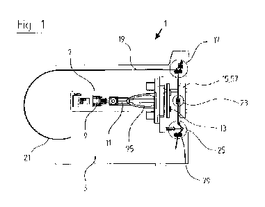
In the schematic side view of a stamping machine 1 for stamping labels and
covers for
containers, such as bottles, cans, tubs, and deep-drawn trays made from
plastic or aluminum,
the reference number 3 designates a side plate which is part of a machine
frame. The essential
elements of the stamping machine 1 comprise a main drive 7 with a servomotor
9, a spindle 11,
a guide element such as a tool carriage which guides the stamping punch 13
linearly in the
direction of a die 57 on a base plate 15, a feed unit 17 for a film 19 as
stamping material in the
form of a web which can be taken off from a coil 21 which serves as a web
store, a stamped
lattice drive 23 which is mounted in the stamping tool, and a dancer roll
element in the form of
a stamped lattice rocker 25.
The stamping material, referred to below as film 19 for short, is supplied to
the stamping
machine 1 from a coil 21. The film 19 is taken off from the coil 21 by the
feed unit 17 which
can be mounted upstream from a dancer roll (Figures 5 to 10).
The feed unit 17 comprises two rolls 29, arranged on axes which extend in
parallel,
which preferably have a rubber coating or jacket 41 on their periphery which
ensures slip-free
feeding of the film 19. At least one of the two rolls 29 can be driven by a
drive motor 53. The
- 7 -
CA 03150711 2022-3-9
two rolls 29 are preferably driven synchronously. The two rolls 29 comprise a
shaft 37 on which
a plurality of magnets 33, arranged axially parallel in a row, are arranged in
bores 35 extending
radially with respect to the axis. The magnets 33 can also be fastened on the
surface of the shaft
37. The shaft 37 can have a round or rectangular cross-section. Bearing rings
39 are arranged
rotatably on the shaft 37 between the magnets 33, distributed over the axial
length of the shaft
37. The inner raceway of the bearing rings 39 is connected non-rotatably to
the shaft 33. The
outer bearing ring 39 carries a tube 38 which forms the rubber jacket. The
shaft 37 forms the
core for the tube 38 with the rubber jacket 41. Toothed wheels 43 are placed
at the two ends of
the shaft 37, connected non-rotatably to the tube 38 at the ends of the tube
38. Two such rolls
29 designed in this manner are carried at their ends by a bearing block 45
(Figure 10).
First shaft bearings 47, rigidly connected to the bearing blocks 45, are
arranged on the
end faces of the bearing blocks 45. Two displaceable second shaft bearings,
fastened to guide
rods 49 on the first shaft bearings 47, carry the second roll 29.
The two rolls 29 are driven in opposite directions with toothed belts 55 by
one or more
drive motors 53. The toothed belt or both toothed belts 55 encircle the
toothed wheels 43 at the
two rolls 29. The toothed wheel or both toothed wheels 47 on the other roll 29
are driven
synchronously by the outer teeth of the toothed belts 55.
In other words, the two rolls 29 can be driven precisely electronically
synchronously
with the same circumferential speeds. The rolls 29 which are thin in
comparison with their axial
length are attracted to each other by the shafts 37 which are arranged in
their center and do not
co-rotate with them or the electromagnets or permanent magnets 33 arranged
thereon. In this
way, a uniform mutual contact pressure of the peripheries of the rubber jacket
41 can be
achieved over the whole axial length. This uniform mutual attractive force of
the rolls 29 which
extends over the whole axial length is maintained irrespective of the
thickness of the film 19
which is guided and conveyed between the two rolls 29. The change in the axial
spacing
between the two rolls 29 because of films 19 of different thickness is
compensated by
displacement of one of the rolls 29 on the guides 49 on which the second shaft
bearing is
mounted so that it is radially displaceable.
The mutual attractive force can be adjusted. For this purpose, the shafts 37
are fastened
on the bearing block 45 so that they can be rotated over a specified angle of
rotation such that
- 8 -
CA 03150711 2022-3-9
the radial spacing of the magnets 33 on the shafts 37 can be adjusted. The
attractive force is
highest when the magnets 33 on the two shafts 37 are situated precisely
opposite each other
between the axes of rotation of the rolls 29; if they are rotated by just a
few angular degrees,
the mutual attractive force decreases correspondingly.
In a simpler embodiment of the shafts 37, only one of the two shafts 37 is
equipped with
magnets 33. The second shaft 37 which is not equipped with magnets 33 is then
produced from
a ferromagnetic material. The angle of rotation of the shafts 37 can be
altered by taking hold of
the end face of the shafts 37.
The film 19 which is taken off from the coil 21 by the feed unit 17 then
passes into the
stamping device 5, i.e. between the stamping punch 13 and the base plate 15
with a die 57
(Figure 11). Stamped lattice drives 59 between the stamping punch 13 and the
die 57 for guiding
the film 19 in the stamping device 5 comprise, outside the stamping device, in
each case a
bearing housing 61 inside which is a gearbox which has conveyor rolls 63
having parallel axes
of rotation which project from the end faces of the housing 61 (Figures 12 to
15). It can
furthermore be seen in Figure 16 that the housing 61 is mounted so that it can
be displaced
vertically with the conveyor rolls 63 in a guide bore which is formed so that
it is perpendicular
in the base plate 15. The low-friction displaceability of the housing 61 and
hence the film drive
59 is ensured by means of ball cages 64. One drive motor 65 is furthermore
arranged in each
case on the bearing housing 61.
As can also be seen in Figure 11, the film drives 59 are arranged in pairs
outside the
periphery of the die 57, and to be precise in such a way that the conveyor
rolls 63 can hold and
then transport the web of film 19, clamped and tensioned, in the longitudinal
edge region of the
latter on the input side and output side during the stamping procedure in the
base plate 15. The
film 19 is consequently held by four pairs of conveyor rolls 63 during the
stamping procedure,
on the one hand, when the film 19 is stationary and, on the other hand, when
it is being
transported. It can consequently contract neither longitudinally nor
transversely nor diagonally.
The stamped lattice which results after the stamping is therefore also held,
tensioned at all times,
when the film 19 exits the stamping region. Even when the majority of the
surface of the web
of film 19 has been stamped out and only narrow strips remain which are no
longer joined
together in a stable fashion, the stamped lattice can be extracted from the
stamping region
- 9 -
CA 03150711 2022-3-9
without it being possible for the side edges of the former unstamped film 19
to contract and the
strips which remain within the stamped lattice to remain stuck in the stamping
device 5. The
film drive 59 necessarily has a highly miniaturized design because it is
situated between the
base plate 15 with the die 57 and the stamping punch 13. The film drive 59
with its conveyor
rolls 63 transports the film 19 between these elements in a stepwise fashion.
In order to be able
to maintain the tension at the edges of the film 19, in particular in the case
of films 19 made
from relatively elastic material, the axes of the conveyor rolls 63 can be
adjusted slightly
obliquely such that they can pull the film 19 constantly outward and hence
hold the film 19
tensioned between the conveyor rolls 63 and appreciably minimize the formation
of wrinkles
or creases in the material. Interruptions in production can be largely
prevented as a result.
By virtue of the vertically displaceable mounting and guidance of the film
drives 59,
enabled by the linear guides 81 which lead out from under the bearing housing
61 and are
mounted so that they can be displaced axially in the base plate 15, the film
drives 59 can be
lifted off from the die 57 during the feeding of the film 19 in a vertical
direction and, when the
stamping device 5 closes, be returned toward the die 17 and brought into
contact with it. This
clearance of the film 19 during the feeding, between the underside of the film
19 and the surface
of the die 57, further favors low-friction transporting of the film 19 when it
is introduced into
the stamping device 5 and, on the other hand, secure transporting of the
stamped lattice away
from the stamping device 5 during the feeding of the film 19.
The stamped lattice that is extracted from the stamping device 5 then passes
over a
second deflection roller 73 into the region of a stamped lattice rocker 25,
generally also referred
to as a dancer roll or dancer roll device (Figures 17 to 20). The stamped
lattice rocker 25 of the
first embodiment (Figures 17-20) comprises a first deflection roller 71 which
can be displaced
axially parallel by a pneumatic cylinder 69 or a spring element and is
parallel to the second
deflection roller 73. The ends of the first deflection roller 71 are mounted
so that they can be
displaced in parallel in bearing blocks 75 on horizontally arranged guide
profiles 77. Arranged
below the first deflection roller 71 is a pair of take-off rolls 79 with two
interacting take-off
rolls 80 with axes of rotation which extend parallel to the axes of rotation
of the first 71 and
second deflection roller 73. The rolls 80 of the pair of take-off rolls 79 can
be driven by a drive
-10 -
CA 03150711 2022-3-9
which has not been illustrated. The structure of the pair of take-off rolls 79
can correspond to
that of the feed unit 17 for taking the film 19 off from the coil 21.
The elements of the stamped lattice rocker 25 are arranged on a common modular
rocker
frame. The stamped lattice rocker 25 also comprises a position sensor 67 by
means of which
the position of the first deflection roller 71 is measured. The first
deflection roller 71 and the
second deflection roller 73, and the rollers 80 of the pair of take-off rolls
79, and the guide
profiles 77 and the position sensor 67, are mounted on a frame which has not
been illustrated
and can be connected to the side plate 3 and/or the machine plinth which has
not been illustrated.
A further particularly advantageous embodiment of the stamped lattice rocker
25 is
illustrated in Figures 21-24. Two pivot arms 99 are articulated on one of two
rocker side plates
97 which are arranged spaced apart from each other in parallel. The pivot arms
99 are pivotably
fastened at one end to the side plates 97 of the rocker frame and can be
adjusted in each case
relative to the side plates 99 of the rocker side plates 97 by a spring
element, for example a
pneumatic cylinder, such that the angle between the side plates 97 can be
adjusted with respect
to a fastening plate of the rocker frame. Inserted between the ends of the
pivot arms 99 which
are situated opposite the pivot axis A is the first deflection roller 71 which
guides the stamped
lattice from the stamping device, following the second deflection roller 73,
over the first
deflection roller 71 and from there to the pair of take-off rolls 79. As in
the first exemplary
embodiment, the film 19 is consequently deflected between the pair of take-off
rolls 99 and the
second deflection roll 73 arranged above the latter such that faults caused by
non-uniform
tension in the film web in the supplying and taking-off of the film can be
compensated by
pivoting of the pivot arms 99 with the first deflection roller 71 fastened
thereon.
The purpose of the stamped lattice rocker 25 is consequently that the stamped
lattice is
transported through the stamping device 5 in a stepwise fashion or
continuously as parallel as
possible to the pair of take-off rolls 79 which forms a second feed unit. The
integrated positional
monitoring by the position sensor 67 of the movable first deflection roller 71
serves to regulate
the speed of the pair of take-off rolls 79. The regulation of the take-off
speed ensures that,
despite the distortion of the stamped lattice, either positively or
negatively, the slippage in the
feed units, position sensors of the feed units, or different roll diameters at
the feed units (wear
of the rubber) can be compensated and the film 19 or the stamped lattice is
consequently guided,
-11 -
CA 03150711 2022-3-9
at all times tensioned and crease-free, at all times between the first feed
unit 17 and the pair of
take-off rolls 79.
The stamped lattice can be sucked away downstream from the pair of take-off
rolls 79
but it can also be wound onto a sleeve for transporting away and disposal.
The main drive 7 illustrated in Figures 2 to 4 serves to stamp the film 19 in
the stamping
device 5, i.e. between the stamping punch 13 and the die on the base plate 15.
The driven shaft
85 of the servomotor 9 can be connected to a spindle 11 (spindle only
partially visible in Figure
2) by means of a clutch 87 or directly. The spindle 11 is rotatably mounted in
a spindle housing
91 and drives a fastening plate 93 for the stamping punch 13. The fastening
plate 93 is guided
in a tool carriage 95 in an axial direction with respect to the spindle 11.
The force acting on the
spindle 11 during the stamping stroke is transmitted from the spindle housing
91 to the side
plate 3.
The servomotor 9 is connected to the machine control system (control system
not
illustrated). The stamping stroke parameters, namely the penetration depth,
i.e. the maximum
stroke of the punch and the minimum stroke of the punch and the acceleration
or deceleration
during the stamping stroke, and, if desired, reversing or stopping points
situated between the
end points of the stamping punch are generated by means of the control system.
These options
for varying the curve executed by the stamping punch 13 during the stamping
stroke can be
generated electronically and additionally adjusted and/or modified at any
moment. It is
consequently possible, without mechanical intervention in the machine when
changing the
thickness of the processed film 19, to make adaptations, on the one hand, to
the materials from
which the film 19 is made but also to its mechanical properties such as
hardness or elasticity
and to its respective thickness. For example, a relatively soft film 19 can
first be compressed
slightly and only then is the stamping procedure performed. Furthermore, the
return stroke, i.e.
the retraction of the punch 13, can also take place with a suitable variable
speed and/or variable
retraction curve.
-12 -
CA 03150711 2022-3-9