Note : Les descriptions sont présentées dans la langue officielle dans laquelle elles ont été soumises.
WO 2021/051165 PCT/AU2020/050988
1
A SENSING DEVICE, SYSTEM AND METHOD FOR A PUMP
Technical Field
[001] The present invention generally relates to a device, system and method
for a pump, and
more particularly to a device, system and method suitable for detecting wear
in a pump.
Background
[002] A slurry pump is a type of pump designed for pumping shiny, slurry being
a liquid
containing solid particles. Variations in design and construction may be occur
to account for
various type of slurry, which may vary in the concentration of solid
particles, the size of solid
particles, the shape of solid particles, and composition of the solution. An
example of a slurry
pump is a centrifugal pump.
[003] Due to the abrasive nature of the medium being pumped, slurry pumps
experience a very
high wear rate on their internal components, such as the main liner that
houses the impeller and
the side liners located on either side of the main liner. A side liner may
include a front sider liner
that is located on the inlet side of the impeller. Alternatively, a side liner
may include the rear side
liner that is located on the opposing side of the impeller. In particular, the
front side liner (which
is also referred to a throatbush) and the main liner (which is also referred
to as a volute) are
subjected to significant amounts of wear.
[004] The performance and wear life of a centrifugal pump directly relates to
the gap that
located between the rotating impeller arid the front side liner. This gap is
particularly important
for slurry pumps as a larger gap results in higher recirculating flow being
generated in the high
pressure region in the pump casing. This recirculating flow reduces the pump
efficiency and also
increases the wear rate on the pump impeller and the front side liner. With
time, as the gap becomes
wider, there is a greater decrease in the pumps performance and an increased
wear rate. Some
conventional side liners can be adjusted axially to reduce the gap. However,
such adjustment does
not alleviate localised wear and any pockets of localised wear will become
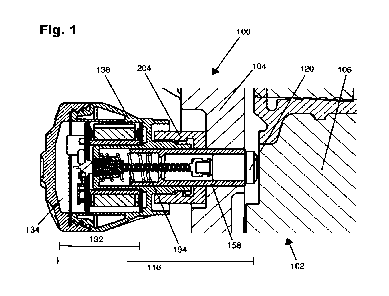
larger over time.
[005] Further, it is important for an operator to have knowledge of the
thickness of the front
side liner, back side liner and main side liner for the practice of effective
maintenance. Such
information would inform the operators of slurry pumps of the optimal time to
replace the liners,
as replacing them too early is financially undesirable and replacing them too
late runs the risk of
CA 03151399 2022-3-16
WO 2021/051165
PCT/AU2020/050988
2
failure of the liner and damage to the impeller, casing and other components.
However, accurately
determining the thickness of the various liners is challenging due to their
location within the thick
outer casing of the pump. As such, it is common for pumps to be disassembled
and visually
inspected for wear, which is a time consuming and costly exercise.
[006] In the past, ultrasonic sensors have been mounted to the outside of the
outer pump casing,
using magnets or other such devices to adhere the ultrasonic sensing device to
the pump. Such
devices may be placed around various locations on the exterior of the pump and
wired together in
order to communicate with one another. However, such solutions require the
determination of the
thickness of the internal components through different surfaces, such as the
thick outer casing. The
outer casing is designed to contain the high pressures generated during
operation of the pump, but
the thickness of the casing decreases the accuracy of external readings.
Further, additional issues
are encountered when measuring the thickness of a front side liner that is
axially adjustable relative
to the main liner.
[007] The preferred embodiments of the present invention seek to address one
or more of these
disadvantages, and/or to at least provide the public with a useful
alternative.
[008] The reference in this specification to any prior publication (or
information derived from
the prior publication), or to any matter which is known, is not, and should
not be taken as an
acknowledgment or admission or any form of suggestion that the prior
publication (or information
derived from the prior publication) or known matter forms liner of the common
general knowledge
in the field of endeavour to which this specification relates_
Summary
[009] This Summary is provided to introduce a selection of concepts in a
simplified form that
are further described below in the Detailed Description. This Summary is not
intended to identify
essential features of the claimed subject matter, nor is it intended to be
used to limit the scope of
the claimed subject matter.
[010] In a first aspect, there is provided by way of example only, a sensing
device for a
centrifugal slurry pump having an impeller which rotates about an axis, the
centrifugal slurry pump
including a side liner and a main liner housed within an outer casing of the
pump, the sensing
device comprising; a body portion arranged to pass through the outer casing,
wherein the body
CA 03151399 2022-3-16
WO 2021/051165 PCT/AU2020/050988
3
portion includes a sensor biased towards contact with either the side liner or
the main liner of the
pump.
[011] In a further example embodiment, the side liner is a front side liner,
the front side liner
comprising a front face and a rear face, the front face is arranged to face
the impeller housed within
the main liner, and the rear face is arranged to face the outer casing,
wherein where the front side
liner is arranged to be axially adjustable with respect to the main liner and
the sensor is arranged
to remain biased towards and in contact with the front side liner when the
front side liner is axially
adjusted with respect to the main liner of the pump.
[012] According to yet further optional aspects, provided by way of example
only, the sensor
senses a distance between the front face and the rear face to provide at least
one thickness reading
for the side liner or the main liner
[013] In a further embodiment, the at least one thickness reading includes a
first thickness
reading and a second thickness reading, where the tint thickness reading and
the second thickness
reading are separated by a period of use of the pump.
[014] In still a further particular, but non-limiting form, the body portion
includes a head
portion, said head portion including a communication module in connection with
the sensor.
[015] In a further, non-limiting embodiment, the head portion is arranged to
locate outside, the
surface of the outer casing.
[016] In a further example embodiment, the communication module transmits each
of the first
thickness reading and the second thickness reading from the sensor to a
computing device.
[017] In yet another example, the computing device compares the first
thickness reading and
the second thickness reading to determine a change in thickness of the main
liner or the side liner
for the period of use.
[018] According to yet further optional aspects, a user of the computing
device axially adjusts
a position of the front side liner relative to the main liner in accordance
with the change in thickness
of the front side liner such that such that the distance between the front
side liner and an impeller
housed in the main liner remains constant.
CA 03151399 2022-3-16
WO 2021/051165
PCT/AU2020/050988
4
[019] In a further embodiment, the body portion includes an elongate tube
member, wherein
the elongate tube member is slidingly received within the head portion.
[020] In a further, non-limiting embodiment, a first end of the elongate tube
member includes
a bias mechanism that biases the elongate tube member towards the main liner
or side liner of the
pump.
[021] In yet another non-limiting example, the bias mechanism is a spring.
[022] According to yet further optional aspects, a second end of the elongate
tube member
portion includes the sensor.
[023] In an embodiment, the body portion includes a connection portion that is
arranged to be
connected to the outer casing.
[024] In yet another example embodiment, the body portion is removably
connected to the
connection portion such that the sensing device passes through the outer
casing of the pump.
[025] According to yet further optional aspects, the body portion is
cylindrically shaped.
[026] In another embodiment, the head portion further comprises at least one
power source.
[027] In another embodiment, the at least one power source is connected to the
communication
module and powers the operation of the sensor.
[028] In yet another example embodiment, the sensing device includes a wired
connection that
joins the communication module to the ultrasonic device.
[029] According to yet further optional aspects, the wired connection arranged
to enable the
relative movement of the elongate tube member relative to the head portion.
[030] In another embodiment, the wired connection is an expandable and
contractible coil of
insulated wire.
[031] In yet another non-limiting embodiment, the at least one power source is
a Lithium
battery.
[032] In a further embodiment, the sensor is an ultrasonic sensor.
CA 03151399 2022-3-16
WO 2021/051165
PCT/AU2020/050988
[033] In another embodiment, the ultrasonic sensor is an ultrasonic
transducer.
[034] According to yet further optional aspects, the ultrasonic transducer is
a piezoelectric
transducer.
[035] In yet another embodiment, the side liner is a rear side liner, wherein
the sensor is
arranged to remain in contact with the rear side liner of the pump.
[036] In a second aspect, there is provided a system for detecting wear in a
centrifugal slurry
pump with a side liner and a main liner housed within an outer casing, said
system comprising a
sensing device arranged to pass through the outer casing, wherein the sensing
device includes a
sensor biased towards and in contact with either the side liner or the main
liner of the pump.
[037] According to yet further optional aspects, the sensor detects a first
thickness reading and
a second thickness reading of either the side liner or the main liner.
[038] In yet another embodiment, the system further includes a computing
device in
communication with the sensing device, the computing device being arranged to
receive the first
thickness reading and the second thickness reading from the sensing device.
[039] In yet another example embodiment, the computing device uses the first
thickness reading
and the second thickness reading to determine a change in thickness of the
side liner or the main
liner_
[040] In yet another non-limiting example, the side liner is a front side
liner arranged to be
axially adjustable with respect to the main liner, wherein a user axially
adjusts the front side liner
relative to the main liner in accordance with the change in thickness of the
front side liner.
[041] In a third aspect, there is provided a method of detecting wear in in a
centrifugal slurry
pump with a side liner and a main liner housed within an outer casing, the
method comprising the
steps of: arranging a sensing device to pass through a surface of the outer
casing, the sensing device
including a sensor; arranging the sensing device relative to the pump such
that the sensor is biased
towards and in contact with the side liner or the main liner; communicating a
first thickness reading
and a second thickness reading of either the side liner or the main liner from
the sensing device to
CA 03151399 2022-3-16
WO 2021/051165 PCT/AU2020/050988
6
a computing device, and determining a change in thickness of the side liner
due to wear using the
computing device.
[042] According to yet another example form, there is provided a device for a
centrifugal slurry
pump with a side liner and a main liner, the side liner being arranged to be
axially adjustable with
respect to the main liner, the device comprising; an ultrasonic sensor adapted
to bias towards
contact with a side liner of the pump, such that the ultrasonic sensor
maintains contact with the
side liner to determine at least one thickness reading for the side liner.
[043] In a fourth aspect, there is provided a sensing device for an unlined
centrifugal slurry
pump having an impeller which rotates about an axis, the centrifugal slurry
pump including an
outer casing of the pump, the outer casing including an inner surface and an
outer surface, the
sensing device comprising; a body portion arranged to engage with a bracket
connected to the
outer surface, wherein the body portion includes a sensor biased towards
contact with the outer
surface of the pump.
[044] In an embodiment, the sensor senses a distance between the outer surface
and the inner
surface to provide at least one thickness reading for the outer casing of the
unlined centrifugal
slurry pump.
[045] In another embodiment, the sensing device is connected to the outer
casing of the unlined
centrifugal slurry pump via a bracket, the bracket arranged to be connected to
at least one non-
wearing face provided to the outer casing.
Brief Description of Figures
[046] Example embodiments are apparent from the following description, which
is given by
way of example only, of at least one non-limiting embodiment, described in
connection with the
accompanying figures.
[047] Fig. 1 illustrates a cross section view of a sensing device in
accordance with an
embodiment of the present invention.
[048] Fig. 2 illustrates a bottom perspective view of an example main liner in
accordance with
an embodiment of the present invention.
CA 03151399 2022-3-16
WO 2021/051165 PCT/AU2020/050988
7
[049] Fig. 3 illustrates a side view of an example main liner in accordance
with an embodiment
of the present invention.
[050] Fig. 4 illustrates a side view of an example front side liner in
accordance with an
embodiment of the present invention.
[051] Fig. 5 illustrates a perspective view of an example front side liner in
accordance with an
embodiment of the present invention.
[052] Fig. 6 illustrates a perspective a cross section view of a sensing
device in accordance with
an embodiment of the present invention.
[053] Fig. 7 illustrates an example user interface for a sensing device in
accordance with an
embodiment of the present invention.
[054] Figs. 8, 8.1 and 8.2 respectively illustrate a side view, bottom
perspective view and top
perspective view of a sensing device in accordance with an embodiment of the
present invention.
[055] Fig. 9 illustrates a top perspective exploded view of a sensing device
in accordance with
an embodiment of the present invention.
[056] Fig. 10 illustrates a top perspective exploded section view of a sensing
device in
accordance with an embodiment of the present invention.
[057] Fig. 11 illustrates a side section view of a sensing device in
accordance with an
embodiment of the present invention.
[058] Fig. 12 illustrates a side section view of a sensing device in
accordance with an
embodiment of the present invention.
[059] Fig. 13 illustrates a perspective exploded view of a sensing device in
accordance with an
embodiment of the present invention.
CA 03151399 2022-3-16
WO 2021/051165 PCT/AU2020/050988
8
[060] Fig. 14 illustrates a bottom perspective view of an example outer casing
of an unlined
pump in accordance with an alternate embodiment of the present invention.
[061] Fig. 15 illustrates a right side view of an example outer casing of an
unlined pump in
accordance with an alternate embodiment of the present invention.
[062] Fig. 16 illustrates an exploded perspective view of an example of a
sensing device in
accordance with an embodiment of the present invention.
[063] Fig. 17 illustrates a perspective view of an example of a sensing device
in accordance
with an embodiment of the present invention.
[064] Fig. 18 illustrates a part view of a perspective view of a sensing
device in accordance
with an embodiment of the present invention.
Detailed Description
[065] The following modes, given by way of example only, are described in
order to provide a
more precise understanding of one or more embodiments. In the figures, like
reference numerals
are used to identify like liners throughout the figures.
[066] With general reference to Figs. 1 to 5, the invention is described in
relation to a centrifugal
slurry pump referred hereafter as "the pump". The pump may be lined or
unlined. That is, a lined
pump includes internal wearing liners and an unlined pump does not. These
wearing liners are
described in further detail below.
[067] A general description of a lined pump 102 is provided as follows. The
pump 102 may
include an outer casing 104, which provides an outer housing for the internal
components of the
pump 102. The outer casing 104 may be formed from cast or ductile iron. The
pump 102 may be
supported by a pedestal or base that is attached to the outer casing 104. The
outer casing 104 may
be formed from two side casing parts or halves (sometimes also known as the
frame plate and the
cover plate) which are joined together about the periphery of the two side
casings parts.
CA 03151399 2022-3-16
WO 2021/051165
PCT/AU2020/050988
9
[068] The pump 102 is formed with an inlet hole and a discharge outlet hole.
When in use, for
example in a process plant, the pump 102 is connected by piping to the inlet
hole and to the outlet
hole, for example to facilitate pumping of a mineral slurry.
[069] The pump 102 may include a side liner and a main liner housed within the
outer casing
104 of the pump 102. More particularly, the outer casing 104 houses a main
liner (or volute) and
two side liners. An example of a main liner 108 is provided in Figs. 2 and 3.
The main liner 108
further defines a pump chamber 110 in which an impeller (not shown) is
positioned for rotation.
The impeller is attached to a drive shaft rotated by a motor, where the drive
shaft drives the
impeller to rotate about an axis within the pump chamber 110.
[070] The outer casing 104 also houses the two side liners, the first being
the rear side liner
(also known as the back liner) is located nearer the rear end of the pump 102
(that is, nearest to
the pedestal or base).The other side liner is a front side liner 106 (also
known as a front liner or
throatbush) and is located nearer the front end of the pump 102 proximate to
the inlet hole or
suction side of the pump 102. Accordingly, the front side liner 106 on the
suction side of the pump
102 is provided with an aperture 112 to accommodate the inlet hole. An example
of a front side
liner 106 is provided in Figs. 4 and 5. The front side liner 106 may further
comprise a front face
114 and a rear face 116, the front face 114 is arranged to face the impeller
housed within the main
liner 108, and the rear face 116 is arranged to face the outer casing 104.
[071] Referring to Fig. 6, an embodiment is provided of a sensing device 100.
The sensing
device 100 may be provided to the pump 102. The sensing device 100 may
comprise a body portion
118 that is arranged to pass through the outer casing 106. In an embodiment,
the body portion 118
includes a sensor 120, which may be arranged to be in contact with either the
side liner 106 or the
main liner 108 of the pump 102. In a further embodiment, the sensor 120 may be
arranged to be
biased towards and in contact with either the side liner 106 or the main liner
108 of the pump 102.
[072] Referring again to Fig. 1, an embodiment is provided where the front
side liner 106 may
be arranged to be axially adjustable with respect to the main liner 108. In
the context of the
specification, the terms "axially adjustable" and "axially adjusted" are taken
to mean that the front
side liner 106 may be translated or moved along the axis of rotation of the
impeller. As such, the
front side liner 106 may be adjusted in order to maintain a constant distance
between the front face
114 and the impeller housed within the main casing 108. In such an embodiment,
the sensor 120
CA 03151399 2022-3-16
WO 2021/051165 PCT/AU2020/050988
is arranged to be biased towards and remain in contact with the front side
liner 106 when the front
side liner 106 is axially adjusted with respect to the main liner 108 of the
pump 102.
[073] In an embodiment, the sensor 120 is an ultrasonic sensor that senses a
distance between
the front face 114 and the rear face 116 to provide at least one thickness
reading for the front side
liner 106. In another embodiment, the sensor 120 is an ultrasonic sensor that
senses a distance
between the inner surface 122 of the main liner 108 (that is, the surface of
the pumping chamber
that faces the impeller) and the outer surface 124 of the main liner (that is,
the surface facing or in
contact with the outer casing 104) to provide at least one thickness reading
for the main liner 108.
[074] Alternatively, the sensor 120 may be an ultrasonic sensor for sensing
the thickness of a
side liner, where the side liner is a rear side liner arranged to locate
between the impeller and the
motor. That is, the rear side liner is on the opposite side of the impeller to
the front side liner. In
all such embodiments, the sensor 120 is arranged to be in contact with and
biased towards the
liners. In the following description, the term "liners" refers interchangeably
to any one of the front
side liner, main liner or the rear side liner of the pump 102. In an
embodiment, the liners may be
made of a wear resistant material such as but not limited to a high-chromium
alloy material.
Alternatively, the liners may be made from a wear resistant elastomeric
material.
[075] The sensor 120 may be an ultrasonic sensor, such as ultrasonic
transducer, which may
include piezoelectric transducers or capacitive transducers. For example, the
transducer may be a
single element, longitudinal wave transducer for use in direct contact.
Alternatively, the transducer
may be a dual element transducer that includes two crystal elements housed in
a single case, the
crystals being separated by an acoustic barrier. One element transmits
longitudinal waves, and the
other element acts as a receiver.
[076] In alternative embodiments, other types of ultrasonic sensors may be
used, such as a
replaceable delay line transducer, which is a single element that is heavily
damped for use with a
replaceable delay line, or an immersion transducer, which is single element,
longitudinal wave
transducer with a quarter-wavelength layer acoustically matched to water. As
such, it is within the
purview of the skilled addressee that other types of ultrasonic transducers
may be used to carry
out the workings of the invention as described and defined within the claims.
[077] The sensor 120 may be arranged to generate ultrasonic pulses and
transmit such pulses
through a medium. The sensor 120 may also be arranged to receive echoes of
such pulses, whilst
CA 03151399 2022-3-16
WO 2021/051165 PCT/AU2020/050988
11
measuring the time interval between when they are received. Using this time
interval, the thickness
of the medium can be determined. For example, the sensor 120 may be arranged
to transmit an
ultrasonic pulse from the rear face 116 of the front side liner 106 and
receive a reflected pulse that
is reflected off the interface formed by the front face 114 of the front side
liner 106. Alternatively,
the sensor 120 may also be arranged to transmit an ultrasonic pulse from the
outer surface 124 of
the main liner 108 and measuring the time interval until the sensor 120
receives the reflected pulse
that is reflected off the interface formed by the inner surface 122 of the
main liner 108.
[078] The sensor 120 may also measure the time interval between the pulse
being transmitted
and the reflected pulse being received. For example, this may be done by
measuring the time
interval between the transmission of the ultrasonic pulse through the liner
and the first returning
echo of that pulse. A small offset value may be subtracted from this time
interval to account for
fixed instrument, cable, and transducer wear plate delays. The thickness of
the liner is determined
using the measured time interval and a known velocity of the sound wave pulse
through the liner,
as the material of the liner and the velocity of an ultrasonic pulse through
the medium is a known
variable.
[079] Alternatively, when referring to Fig. 7, an example of a user interface
is provided. The
user interface merely provided to demonstrate a method by which the thickness
of the liner may
be determined by measuring the time interval between two successive backwall
echoes. A
backwall echo is a soundwave that rebounds of the distal boundary of the
liner. For example, as
shown in Fig. 7, for a sensor 120 in contact with a front side liner 106, the
first interface echo 126
is the reflected sound signal from the ultrasound pulse reflecting off the
rear face 116 of the front
side liner 106. Further, a first backwall echo 128 and a successive second
backwall echo 130 are
the reflected sound signals from the ultrasound pulse reflecting off the front
face 114 of the front
side liner 106. The thickness of the liner between the rear face 116 and the
front face 114 may be
determined by measuring the time period between the first backwall echo 128
and second backwall
echo 130. That is, the second back wall echo is part of the ultrasound pulse
that has travelled
through the liner twice. As would be understood by skilled addressee, this
measurement may be
taken multiple times for single point in time and combined to form a thickness
reading. The
combination of multiple measurements into a single reading may improve the
accuracy of the
readings. For example, a thickness reading may include an average of
approximately five to ten
individual measurements.
CA 03151399 2022-3-16
WO 2021/051165 PCT/AU2020/050988
12
[080] In an embodiment, the sensor 120 may be arranged to sample at least one
thickness
reading within the same period of use of the pump 102, where the period of use
is understood to
mean a discrete period of time over which the pump is in operation. The sensor
120 may be
arranged to sample at least one thickness reading, where the at least one
thickness reading may
include a first thickness reading and a second thickness reading. The first
thickness reading and
the second thickness reading are separated by a period of use of the pump 102.
That is, the sensor
120 may be arranged to measure the thickness of the liner at two different
points in time, where
the pump 102 has been in use and has been subject to wear during the period
between these two
points in time.
[081] In an embodiment, the sensing device 100 may include a polymer putty
that is located
between the sensor 120 and the liner. The polymer putty may improve the
effectiveness of the
transmission of the ultrasound pulse into the liner and reduce the magnitude
of the interface echo.
The polymer putty may also provide a small adhesive effect that additionally
increases contact
with the sensor 120 and the liner.
[082] In an embodiment, the body portion 118 includes a head portion 132, said
head portion
132 including a communication module 134 in connection with the sensor 120.
The
communication module 134 may be arranged to transmit data collected from the
sensor 120 to a
computing device. The data may be representative of a time period between
various ultrasound
pulses and reflections as described above. The terms data refers to the
information transmitted via
a signal. The data may incorporate multiple readings from the sensor at a
single point in time or
across multiple points in time.
[083] In an embodiment., the communication module 134 may include a
communication unit
arranged to facilitate the communication of data between the sensing device
100 and a computing
device. The computing device describes a separate computer under the control
of the user that is
arranged to undertake further analysis of the data collected by the sensing
device 100. The
computing device may also be configured to store the data collected by the
sensing device 100 and
may include servers or other computers that are connected to the computing
device via a network.
A person skilled in the art would understand that the term computing device
describes a broad
range of computing devices, technology and architectures.
[084] The communication unit may include a Bluetooth Low Energy (BLE) module
and
antenna for short range and long range communication with the computing
device, or another
CA 03151399 2022-3-16
WO 2021/051165
PCT/AU2020/050988
13
wireless personal area network communication device or technology. The
communication unit
may be programed to include a communication cycle, where the communication
module 134
remains mostly inactive in a power conservation mode and will only transmit
data to the computing
device at a time optimal for battery conservation, such as when a device
capable of receiving the
data is detected as being in range. For example, when a user with a computing
device, that may
include a mobile device such as a smart phone, laptop or tablet, comes in
range of the
communication unit.
[085] The communication module 134 may also include a processor, such as a
Central
Processing Unit (CPU) for the processing of data and other such operations.
Further, the
communication module may include a memory module that includes both volatile
and non-volatile
data storage so that data from the sensor 120 may be stored on the sensing
device 100 to be
transmitted to the computing device at a later time. The data storage may be
arranged with such a
capacity to store hundreds or thousands of data sets collected by the sensor
120.
[086] In an embodiment, the communication module 134 may be arranged to enable
"remote
processing" of data collected by the sensor 120. Remote processing within the
context of the
specification is understood to mean that the sensing device 100 is responsible
for the collection
and transmission of data, whilst the computing device is responsible for
processing, transforming
and contextualising the data to form information. That is, the communication
module 134 may be
arranged to filter an analogue data received from the sensor 120 to reduce or
remove noise and
artefacts and/or convert the analogue data gathered by the sensor 120 into
digital data and transmit
the digital data to the computing device. Once transmitted, the computing
device may convert this
data into a thickness reading. Alternatively, the sensor 120 may be arranged
to filter analogue data
received from the sensor 120 to reduce or remove noise and artefacts and/or
convert the analogue
data into digital data, where the communication module 134 then transmits the
digital data to the
computing device to be converted into a thickness reading.
[087] In an alternate embodiment, the communication module 134 may be arranged
to provide
"on-board" processing. On-board processing within the context of the
specification is understood
to mean that the sensing device 100 is responsible for collecting, processing,
transforming and
contextualising the data to form information and transmitting the information
to a computing
device. For example, the CPU may be arranged to do one or more of; filter
analogue data received
from the sensor 120 to reduce or remove noise and artefacts, convert the
analogue data received
from the sensor 120 into digital data, and use the digital data to determine
at least one thickness
CA 03151399 2022-3-16
WO 2021/051165
PCT/AU2020/050988
14
reading. For example, the communication module 134 may be arranged to
determine the at least
one thickness reading from data received from the sensor 120 and transmit the
at least one reading
to the computing device.
[088] In an embodiment, the computing device may be arranged to perform
additional analysis
or processing of the data. For example, the computing device may compare the
first thickness
reading and the second thickness reading to determine a change in thickness of
the main liner or
the side liner for the period of use. In other words, the computing device may
determine the change
in liner thickness by subtracting the first thickness reading from the second
thickness reading. By
knowing the change in liner thickness, a user will be able to determine the
level of wear
experienced by the internal components of the pump, which would be otherwise
near impossible
to determine without dissembling the pump.
[089] In an embodiment, where the front side liner 106 may be arranged to be
axially adjustable
with respect to the main liner 108, the sensing device 100 enables a user to
axially adjust a position
of the front side liner 106 relative to the main liner 108 in accordance with
the change in thickness
of the front side liner 106. In other words, the user changes the position of
the front side liner 106
to maintain a constant distance between the front side liner 106 and an
impeller housed in the main
liner 108.
[090] The user may use the change in liner thickness to optimise the
performance of the pump
without having to disassemble the pump. That is, as the front face 114 of the
front side liner 106
wears out, the user axially adjusts the front side liner 106 by moving the
front side liner 106
towards the impeller by the same distance as the change in thickness to ensure
that the gap between
the impeller and front side liner 106 remains in the optimal range. Otherwise,
with an increased
gap, the increases the recirculating flow reduces the pump efficiency and
increases the wear rate
on the pump impeller and the front side liner 106.
[091] Referring now to Fig. 1 and Figs. 8 to 11, an embodiment is provided
wherein the body
portion 118 includes a head portion 132, where said head portion 132 includes
the communication
module 134 in connection with the sensor 120.
[092] The head portion 132 may be arranged to align with, or locate outside,
the surface of the
outer casing 104. Referring in particular to Fig. 1, the head portion 132 may
be arranged to extend
through the entirety of and protrude past the surface of the outer casing 104.
Alternatively, the
CA 03151399 2022-3-16
WO 2021/051165
PCT/AU2020/050988
head portion 132 may be arranged to sit within a recess formed within the
outer surface of the
outer casing 104 (not shown) such that the head portion 132 sits flush with
respect to the outer
surface of the outer casing 104. By locating at least part of the head portion
132 outside the thick
outer casing 104 or in line with outer casing 104, the sensor device 100 is
able to wirelessly
communicate the data collected by the sensor 120 to the computing device.
[093] As shown in the Figs. 9 and 10, the head portion 132 may include a cap
136, which is
arranged to removably connect to a base 138. The connection between the cap
136 and the base
138 provides a watertight seal that prevents water and other contaminants like
dirt, mud or oil from
penetrating into the head portion 132. The cap 136 may connect to the base 138
by means of a
screw connection facilitated by a mating thread provided to an outer rim of
the base 138 and the
inner rim of the cap 136. Alternatively, the cap 136 may connect to the base
138 by means of a
snap fit connection. Such methods of connection are provided as examples to
demonstrate the
workings of the invention. Therefore, in light of such variations, the skilled
addressee would
understand that other similar means of removably connecting the cap 136 to the
base 138 in a way
that facilitate a water and dirt proof housing would be understood to fall
within the scope of the
invention as described and defined in the claims.
[094] The base 138 may be shaped to form a recess 140, the recess 140 being
arranged to receive
a power source housing 142, the power source housing 142 being arrange to
retain at least one
power source 144. The base 138 may also include a hollow housing 146, the
hollow housing 146
having a first end and a second end. The first end 148 of the hollow housing
146 protrudes upwards
from the floor of the base 138, where the first end 148 of the hollow housing
146 is receivable
within a recess formed in the centre of the power source housing 142. When the
head portion 132
is assembled, the first end 148 is arranged to sit proximate to the at least
one power source 144
and the communication module 134. This arrangement is clearly shown in Fig.
11, where the first
end 148 is proximate to the at least one power source 144 and the
communication module 134.
Further, the first end 148 is formed with an aperture 150 that enables access
to the interior 152 of
the hollow housing 146. As shown, the aperture 150 may have a smaller diameter
than the diameter
of the interior 152 due to a circular lip 154.
[095] The hollow housing 146 may be arranged to extend past the base 138 of
the head portion
132, such that the second end 155 of the hollow housing 146 is distally
located with respect to the
at least one power source 144 and the communication module 134. The second end
155 of the
CA 03151399 2022-3-16
WO 2021/051165 PCT/AU2020/050988
16
hollow housing 146 is formed with an opening 156, the opening 156 having the
same diameter as
the diameter of the interior 152. That is, the opening 156 does not contain a
neck or lip.
[096] In an embodiment, the body portion includes an elongate tube member. The
elongate tube
member may be arranged to be fixed or integrally formed with the head portion
132. Alternatively,
Fig. 12 provides an embodiment where the body portion 118 includes an elongate
tube member
158, wherein the elongate tube member 158 is slidably received within the head
portion 132. The
opening 156 may be arranged to slidably receive the elongate tube member 158,
which for
convenience is here after referred to as the "tube member" The tube member 158
is hollow and is
sized to be freely slidable within the interior 152 of the hollow housing 146.
The tube member 158
includes two ends, a first end 160 arranged to be received within the opening
156 and slidable
within the interior 152. The outer diameter of the tube member 158 remains
constant along its
length. The second end 162 of the tube member 158 is arranged to retain the
sensor 120. The first
end 160 of the elongate tube member 158 may include a bias mechanism that
biases the elongate
tube member 158 towards the main liner 108 or side liner 106 of the pump 102
relative to the head
portion 132.
[097] The tube member 158 further includes an elongate interior 164 bounded
and defined by
an inner diameter. In an embodiment, the inner diameter along the length of
the tube member 158
may vary to define different sections of the elongate interior 164. For
example, as shown in Fig.
12, the tube member 158 includes a first section 166, the first section 166
being a portion of the
elongate interior 164 arranged to locate between the first end 160 and a
second section 168 of the
of the elongate interior 164. The inner diameter of the second section 168 is
less than the diameter
of the first section 166, such that the boundary of the first section 166 and
the second section 168
forms a step 170.
[098] The tube member 158 may also include a third section 172, which is
arranged to locate
between the second section 168 and the second end 162 of the tube member 158.
The inner
diameter of the second section 168 is less than the diameter of the third
section 172, such that the
boundary of the second section 168 and the third section 172 forms a flange
174.
[099] In another embodiment, an alternate arrangement is provided with
alternate elongate tube
member 176. Alternate tube member 176 may include a first section 178, the
first section 178
being a portion of the elongate interior 180 arranged to locate between the
first end 182 of the
alternate tube member 176 and a second section 184 of the of the elongate
interior 180. The inner
CA 03151399 2022-3-16
WO 2021/051165
PCT/AU2020/050988
17
diameter of the second section 184 is less than the diameter of the first
section 178, such that the
boundary of the first section 178 and the second section 184 forms a step 186.
[0100] The alternate tube member 176 may also include a third section 188,
which is arranged
to locate between the second section 184 and the second end 190 of the
alternate tube member
176. The inner diameter of the second section 184 is less than the diameter of
the third section
188, such that the boundary of the second section 184 and the third section
188 forms a flange
192.
[0101] As can be seen from the tube member 158 and the alternate tube member
176, the tube
members may include different variations and permutations of arrangements,
sizes, diameters and
lengths may be used to suit different types of pumps and for use in measuring
different liners for
pumps. For example, tube member 158 may be used with a front side liner 106
and alternate tube
member 176 may be used with a main liner 108. Further variations in the tube
member 158 may
also be present to incorporate whether the liner is axially adjustable within
the pump 102.
[0102] In an embedment, the first end of the tube member 158 includes a bias
mechanism that
biases the tube member 158 towards the main liner 108 or side liner 106 of the
pump 102 relative
to the head portion. For example, the tube member 158 includes a spring 194. A
first end 196 of
the spring 194 abuts the lip 154 formed by the first end 148 of the hollow
housing 146. A second
end 198 of the spring 194 abuts the step 170 formed at the boundary of the
first and second portions
166, 168, and when so arranged, the spring 194 is in a state of compression.
The sensor 120 is at
least partially housed within the third section 172 at the second end 162 of
the tube member 158.
As such, the bias mechanism, in this case the spring 194 whilst in a state of
compression, biases
the sensor 120 to be in contact with the liner of the pump 102. This in turn
enables the sensor 120
to more accurately measure the thickness of the liner of the pump 102 as the
sensor 120 constantly
remains in contact with the liner due to the force of the bias.
[0103] Further, in an embodiment where the liner is a front side liner 106 and
is axially
adjustable, the bias mechanism enables the sensor 120 to remain in contact
with the front side liner
106 whilst the user is axially adjusting the front side liner 106 with respect
to the main liner 108.
This in turn enables the sensor 120 to more accurately measure the thickness
of the front side liner
106 of the pump 102 as the sensor 120 is always in contact with the front side
liner 106 regardless
of the front side liner's axial position within the pump 102. This is clearly
shown in Fig. 1, where
the front side liner 106 has moved away from outer casing 104 and this
movement has caused a
CA 03151399 2022-3-16
WO 2021/051165
PCT/AU2020/050988
18
gap to form between these components, where the gap is breached by the
expansion of the
compressed spring 194 which biases the sensor 120 to be in contact with the
front side liner 106.
[0104] In an embodiment, the head portion 132 may further comprise at least
one power source
144. For example, as shown in Fig. 11, the head portion 132 includes two power
sources 144 that
are provided on opposing sides within the head portion 132. Such power sources
may include, but
are not limited to, Lithium batteries, for example CR123A 3 Volt Lithium
batteries. Alternatively,
as shown in Fig. 9, a symmetrical arrangement of four batteries is provided,
although only three
of these batteries are viewable. Further, another embodiment is provided where
the head portion
132 houses eight batteries. Therefore, it would be understood by the skilled
addressee that other
arrangements, numbers of batteries and types of batteries and power sources
would be understood
to be within the scope of the invention as described and defined in the
claims.
[0105] In an embodiment, the at least one power source 144 is connected to the
communication
module 134 and powers the operation of the sensor 120. In other words, the at
least one power
source is arranged to provide power to the sensor 120 via the communication
module 134. The
communication module 134 may include various circuitry components to transform
the voltage
from the power source to the voltage required by the sensor to transmit an
ultrasonic pulse. For
example, the communication module may include a DC to DC step up converter or
transformer to
convert 3 Volts from the power source to 400 Volts as required by the sensor
120.
[0106] As such, the connection between the communication module 134 and the
sensor 120 is
arranged to enable the relative movement between the sensor 120 and tube
member 158 relative
to the rest of the head portion 132. For example, the sensing device 100
includes a wired
connection 200 that joins the communication module 134 to the sensor 120. The
wired connection
200 is arranged to enable the relative movement of the sensor 120 and tube
member 158 relative
to the head portion 132. In an embodiment, the wired connection 200 is an
expandable and
contractible coil of insulated wire, capable transmitting electrical and data
signals between the
sensor 120 and the communication module 134. The wired connection 200 may be
arranged to
pass through the opening 156 and along the elongate interior 164. The wired
connection 200 may
be formed in a helical coil along at least part or all of its length.
[0107] Referring now to Figs. 11 and 13, an embodiment is provided wherein the
body portion
118 and/or head portion 132 includes a connection portion 204 that is arranged
to be connected to
the outer casing 104. The body portion 118 and/or head portion 132 may be
removably connected
CA 03151399 2022-3-16
WO 2021/051165 PCT/AU2020/050988
19
to the connection portion 204 which holds the body portion and/or head portion
to enable the
sensing device 100 to pass through the outer casing 104 of the pump 102. An
aperture 202 may be
formed to extend through the outer casing 104. The connector portion 204 may
be fastened to the
outer casing 104 by means of screws 206 or similar fastening devices that
enable a robust and tight
connection. The connector portion 204 may be arranged such that an aperture
208 formed in the
connection portion 204 aligns with the aperture 202 formed in the outer casing
104.
[0108] The body portion 118 may be received and retained within the apertures
202 and 208.
The body portion 118 and the connection portion 204 may each include
respective connective
cammed surfaces that engage with one another to removably connect the body
portion 118 to the
connection portion 204. For example, as shown in Figs. 11 and 13, the
connection portion 204 and
the body portion 118 may connect together using a bayonet connection 210.
However, the skilled
addressee would understand that other similar mechanical means of removably
and securely
attaching the body portion 118 and/or head portion 132 to the connection
portion 204 may be
available, and hence connecting the sensing device 100 to the pump 102.
[0109] Referring to Figs. 14 to 18, an alternate embodiment is provided for
sensing device 100
for use with an unlined pump 212. An unlined pump 212 is one that does not
include separate
liners that experience wear. Instead, the inner surface 218 of the outer
casing 216 of the unlined
pump 212 experiences wear during the pumping process. The outer casing 216 may
be formed
from the same wear resistant material as the liners as described above. The
unlined centrifugal
slurry pump 212 includes an impeller that rotates about an axis. Further,
referring to Figs. 14 and
15, the unlined centrifugal slurry pump 212 includes an outer casing 216, the
outer casing 216
including an inner surface 218 and an outer surface 220.
[0110] In an embodiment, a sensing device 100 for an unlined centrifugal
slurry pump 212 is
provided. The sensing device 100 may comprise a body portion 118 arranged to
engage with a
bracket 214 connected to the outer surface 220, wherein the body portion 118
includes a sensor
120 in contact or biased towards contact with the outer surface 220 of the
unlined centrifugal slurry
pump 212.
[0111] In such an embodiment, the sensing device 100 may be alternatively
provided so that the
sensor 120 senses a distance between the outer surface 220 of the outer casing
216 and an inner
surface 218 of the outer casing 216 to provide at least one thickness reading
for the outer casing
CA 03151399 2022-3-16
WO 2021/051165
PCT/AU2020/050988
216. That is, the sensor 120 may be arranged to transmit an ultrasonic pulse
from the outer surface
220 of the outer casing 216 and measure the time interval until the pulse
reflected of the interface
formed by the inner surface 218 of the outer casing 216.
[0112] In an embodiment, the sensing device 100 may be connected to the outer
casing 216 of
the unlined centrifugal slurry pump 212 via an elongate bracket 214. In one
embodiment, the
connection portion 204 of the body 118 may be connected to the bracket 214 in
a similar manner
to how the connection portion 204 connects to the outer casing 202 of the
lined pump 102
embodiments. In turn, the ends of the bracket 214 are connected to a non-
wearing face 222 the
outer casing 216 of the unlined pump 212. As shown in Fig. 16, the bracket 214
is arranged to
extend around or over a portion of the outer casing 216 and connect to the non-
wearing face 222
provided on either side of the unlined pump 212. In an example, the bracket
may include a metal
plate that includes an aperture that is configured to receive and engage with
the connection portion
204, by means of mechanical fasteners, snap fit arrangements, or canuned
surfaces.
[0113] Connection of the sensing device 100 to the unlined pump 212 by means
of the bracket
214 removes the requirement to drill into the outer casing 216. Drilling into
the casing of an
unlined pump 212 is difficult and expensive due of the wear resistant material
used for the outer
casing 216. Further, drilling into the outer casing 216 will also compromise
the strength and
thickness of the wearing part, which may lead to premature failure of the
unlined pump 212, where
such failure may be catastrophic.
[0114] Referring to Fig. 17, a number of alternate embodiments are provided.
In an embodiment,
at least one sensing device 100 is connected to an unlined pump 212. In the
example shown, the
at least one sensing device 100 includes six sensing devices 100. The sensing
devices 100 may be
arranged in various arrangements in order to measure the thickness of the
outer casing 216 of the
unlined pump 212. The arrangement and relative positions of the sensing
devices 100 shown are
merely provided as an example, as a person skilled in the art would understand
that such locations
are non-limiting. Further, the skilled addressee would also understand that an
arrangement of
multiple sensing devices 100 may also be used to measure the thickness of
various liners or various
sections of a lined in a pump 102.
[0115] In an embodiment, five of the six sensing devices 100 are connected to
the bracket 214
and one of the sensing devices 100 being connected directly to the non-wearing
face 222. As such,
an embodiment is provided wherein the non-wearing face 222 may be configured
to receive and
CA 03151399 2022-3-16
WO 2021/051165 PCT/AU2020/050988
21
engage with the connection portion 204, by means of mechanical fasteners, snap
fit arrangements,
or cammed surfaces.
[0116] In an embodiment, the sensing device 100 may be provided in a generally
cylindrical
shape. As such, the head portion 132 and the tube member 156 may be
cylindrically shaped. That
is, they have an approximate cross sectional shape of a circle along a first
axis and are elongate
along another perpendicular axis. However, as would be understood by the
skilled addressee, other
shapes may be contemplated to accommodate different sizes or shaped sensors
120, positions of
the liner or variations in the pumps. Therefore, the person skilled in the art
would understand that
variations in the size and general shape of the sensing device 100 is within
the scope of the
invention as described and defined in the claims.
[0117] Figure 18 depicts a further embodiment where the sensing device may be
coupled to a
connecting portion 204 which itself may be adhered to the non-wearing face of
the outer surface
222 of the unlined pump casing.
[0118] With reference to Figs. 1 to 13, there is provided an embodiment fora
system for detecting
wear in a centrifugal slurry pump 102. The pump 102 includes a side liner 106
and a main liner
108 housed within an outer casing 104. The system comprises at least one
sensing device 100
arranged to pass through the outer casing 104, wherein the at least one
sensing device 100 includes
a sensor 120 biased towards contact with either the side liner 106 or the main
liner 108 of the pump
102. The at least one sensing device 100 may be arranged to detect a first
thickness reading and a
second thickness reading using the sensor 120. The first thickness reading and
the second thickness
reading may be in respect of the side liner 106 or the main liner 108 of the
pump.
[0119] In an embodiment, the system may further include a computing device
that is arranged in
communication with the at least one sensing device 100. The computing device
may be arranged
to receive the first thickness reading and the second thickness reading from
the at least one sensing
device 100. The computing device may then use the first thickness reading and
the second
thickness reading to determine a change in thickness of the side liner 106 or
the main liner 108
due to wear incurred during the operation of the pump 102.
[0120] In an embodiment, the side liner 106 is a front side liner that is
arranged to be axially
adjustable with respect to the main liner 108. Upon determining the change in
the thickness of the
front side liner 106, a user axially adjusts the front side liner 106 relative
to the main liner 108 in
CA 03151399 2022-3-16
WO 2021/051165
PCT/AU2020/050988
22
accordance with the change in thickness of the front side liner 106. This
enables the optimum
distance between the front side liner 106 and the impeller to be maintained.
[0121] Again, with reference to Figs. 110 13, there is provided an embodiment
for a method of
detecting wear in in a centrifugal slurry pump. The centrifugal slurry pump
including a side liner
106 and a main liner 108 housed within an outer casing 104 of the pump 102.
The method
comprising the steps of firstly arranging at least one sensing device 100 to
pass through a surface
of the outer casing 104. The at least one sensing device 100 includes a sensor
120 capable of
detecting the thickness of the either the side liner 106 or the main liner
108. Further, the at least
one sensing device 100 is arranged such that the sensor 120 is biased towards
contact with either
the side liner 106 or the main liner 108.
[0122] The method further includes the step of communicating a first thickness
reading and a
second thickness reading of either the side liner or the main liner from the
at least one sensing
device 100 to a computing device. Once the first and second thickness readings
have been
communicated to the computing device, the computing device determines a change
in thickness
of the side liner due to wear using the pump 102.
[0123] The sensing device referred to herein may be made of any material
suitable for being
shaped, formed or fitted as described, such as a plastic material. The plastic
material may have
properties such as high mechanical strength and impact resistance, High Glass
Transition
Temperature (Tg), UV resistance, water resistance, high dimensional stability
and good chemical
resistance. For example, the body portion 118 may be made from a thermoplastic
such as
Acrylonitrile styrene acrylate (ASA) or other similar composite materials. The
spring 194 may be
made from a metallic material or alloy that enables effective storage of
mechanical energy. For
example, the sprint 198 may be made of stainless steel.
[0124] In the foregoing description of preferred embodiments, specific
terminology has been
resorted to for the sake of clarity. However, the invention is not intended to
be limited to the
specific terms so selected, and it is to be understood that each specific term
includes all technical
equivalents which operate in a similar manner to accomplish a similar
technical purpose. Terms
such as "front" and "rear", "above" and "below" and the like are used as words
of convenience to
provide reference points and are not to be construed as limiting terms.
CA 03151399 2022-3-16
WO 2021/051165 PCT/AU2020/050988
23
[0125] Optional embodiments may also be said to broadly include the parts,
elements, steps
and/or features referred to or indicated herein, individually or in any
combination of two or more
of the parts, elements, steps and/or features, and wherein specific integers
are mentioned which
have known equivalents in the art to which the invention relates, such known
equivalents are
deemed to be incorporated herein as if individually set forth.
[0126] Although a preferred embodiment has been described in detail, it should
be understood
that modifications, changes, substitutions or alterations will be apparent to
those skilled in the art
without departing from the scope of the present invention.
[0127] Throughout this specification and the claims which follow, unless the
context requires
otherwise, the word "comprise", and variations such as "comprised",
"comprises" or
"comprising", will be understood to imply the inclusion of a stated integer or
step or group of
integers or steps but not the exclusion of any other integer or step or group
of integers or steps.
[0128] As used herein, a, an, the, at least one, and one or more are used
interchangeably, and
refer to one or to more than one (i.e. at least one) of the grammatical
object. By way of example,
"an element" means one element, at least one element, or one or more elements.
[0129] In the context of this specification, the term "about" is understood to
refer to a range of
numbers that a person of skill in the art would consider equivalent to the
recited value in the context
of achieving the same function or result.
Advantages
[0130] The embodiments described herein provide a novel means of enabling a
user to determine
the thickness of a liner within a pump at various points along that liner.
Further, the embodiments
described enable a user to determine the thickness of a liner with improved
accuracy over any
current techniques. In particular the arrangement of the sensor biased towards
the main liner, side
liner and/or casing provides that there is little to no air gap provided
between the sensor and the
main liner, side liner and/or casing which increases the accuracy of the
readings.
[0131] The device, system and methods described herein provide the user with
information that
allows them to identify the optimal time to replace or repair the liners.
Replacing or repairing the
liners at the optimal time avoids the financially cost of replacing the liners
too early. Moreover,
CA 03151399 2022-3-16
WO 2021/051165
PCT/AU2020/050988
24
replacing or repairing the liners before they suffer too much wear also
reduces the risk of failure
of the liner and damage to the impeller, casing and other components.
Essentially, the
embodiments described provide accurate and relevant information to operators
and users to
remove the "guess work" about undertaking optimised maintenance of the pumps.
Further, this
information is obtained without having to open the pump and visually inspect
the liners, which is
a time consuming and costly process.
[0132] Further, these embodiments enable the thickness of an axially
adjustable front side liner
to be determined, for which there are no current solutions that are able to
accommodate this axial
adjustment when determining the thickness of the front side liner.
[0133] Moreover, the embodiments describe a sensing device that is able be
retrofitted to existing
pumps without compromising the integrity of the outer casing when operating
under high-pressure
conditions.
[0134] Further, the embodiments described enable the wireless communication of
information
relating to that thickness to a user in a quick effective manner. Moreover,
the interchangeability
of the parts enables easy and cost effective replacement of the sensing
devices and easy and cost
effective modification of the sensing devices to suit different pumps.
[0135] Further, the sensing device described may be able to run various types
of software that
will enable the sensing device to communicate with any "smart" device with the
appropriate
software installed, as described above. As such, the wide scale application of
this device, system
and method would not be limited to communicating data to any particular device
or platform.
[0136] In a further advantageous aspect, the embodiments described provide a
device that, once
installed initially, the sensing device may be removed and attached easily and
without tools.
Moreover, the easily to remove design of the sensing device improves the
serviceability and
maintainability of the pump.
[0137] Moreover, once sufficient thickness readings and such data has been
collected from the
sensing device, the above mentioned further analysis of the date by the
computing device may
include forecasting when a pump requires service with much greater accuracy
than the current
available methods.
CA 03151399 2022-3-16