Note : Les descriptions sont présentées dans la langue officielle dans laquelle elles ont été soumises.
CA 03152832 2022-02-28
WO 2021/038192
PCT/GB2020/051932
AEROSOL PROVISION SYSTEMS
Field
The present disclosure relates to aerosol provision systems such as nicotine
delivery
systems (e.g. electronic cigarettes and the like).
Background
Electronic aerosol provision systems such as electronic cigarettes (e-
cigarettes) generally
contain an aerosol precursor material, such as a reservoir of a source liquid
containing a
formulation, typically including nicotine, or a solid material such a tobacco-
based product,
from which an aerosol is generated for inhalation by a user, for example
through heat
vaporisation. Thus, an aerosol provision system will typically comprise a
vaporiser, e.g. a
heating element, arranged to vaporise a portion of precursor material to
generate an aerosol
in an aerosol generation region of an air channel through the aerosol
provision system. As a
user inhales on the device and electrical power is supplied to the vaporiser,
air is drawn into
the device through one or more inlet holes and along the air channel to the
aerosol
generation region, where the air mixes with the vaporised precursor material
and forms a
condensation aerosol. The air drawn through the aerosol generation region
continues along
the air channel to a mouthpiece opening, carrying some of the aerosol with it,
and out
through the mouthpiece opening for inhalation by the user.
It is common for aerosol provision systems to comprise a modular assembly,
often having
two main functional parts, namely a control unit and disposable / replaceable
cartridge part.
Typically the cartridge part will comprise the consumable aerosol precursor
material and the
vaporiser (atomiser), while the control unit part will comprise longer-life
items, such as a
rechargeable battery, device control circuitry, activation sensors and user
interface features.
The control unit may also be referred to as a reusable part or battery section
and the
replaceable cartridge may also be referred to as a disposable part or
cartomiser.
The control unit and cartridge are mechanically coupled together at an
interface for use, for
example using a screw thread, bayonet, latched or friction fit fixing. When
the aerosol
precursor material in a cartridge has been exhausted, or the user wishes to
switch to a
different cartridge having a different aerosol precursor material, the
cartridge may be
removed from the control unit and a replacement cartridge may be attached to
the device in
its place.
A potential drawbacks for cartridges containing liquid aerosol precursor (e-
liquid) is the risk
of leakage. An e-cigarette cartridge will typically have a mechanism, e.g. a
capillary wick, for
drawing aerosolisable material from an aerosolisable material reservoir to a
vaporiser
1
CA 03152832 2022-02-28
WO 2021/038192
PCT/GB2020/051932
located in an air path / channel connecting from an air inlet to an aerosol
outlet for the
cartridge. Because there is a fluid transport path from the aerosolisable
material reservoir
into the open air channel through the cartridge, there is a corresponding risk
of aerosolisable
material leaking from the cartridge. Leakage is undesirable both from the
perspective of the
end user naturally not wanting to get the e-liquid on their hands or other
items, and also from
a reliability perspective, since leakage from an end of the cartridge
connected to the control
unit may damage the control unit, for example due to corrosion. Some
approaches to reduce
the risk of leakage may involve restricting the flow of aerosolisable material
to the vaporiser,
for example by tightly clamping a wick where it enters the air channel. In
normal use, the
aerosolisable material taken up by the wick is sufficient to keep the
vaporiser cool (i.e., at an
ideal operating temperature), but when the aerosolisable material taken up is
insufficient
(e.g., when the aerosolisable material in the reservoir runs low) this can in
some scenarios
give rise to overheating and undesirable flavours.
Various approaches are described herein which seek to help address or mitigate
some of
the issues discussed above.
Summary
According to a first aspect of certain embodiments there is provided a
cartridge for an
aerosol provision system comprising the cartridge and a control unit, wherein
the system
comprises a vaporiser for vaporising an aerosolisable material, wherein the
cartridge
comprises:
an air channel extending from an air inlet for the cartridge to an outlet via
an aerosol
generation region;
a reservoir for containing aerosolisable material for aerosolising;
wherein the cartridge further comprises an aerosolisable-material-level
observation means
for allowing a user to observe a level of aerosolisable material inside the
reservoir.
According to a second aspect of certain embodiments there is provided an
aerosol provision
system comprising the cartridge from the first aspect and a control unit,
wherein the control
unit comprises a cartridge receiving section that includes an interface
arranged to
cooperatively engage with the cartridge so as to releasably couple the
cartridge to the
control unit, wherein the control unit further comprises a power supply and
control circuitry.
It will be appreciated that features and aspects of the invention described
above in relation to
the various aspects of the invention are equally applicable to, and may be
combined with,
embodiments of the invention according to other aspects of the invention as
appropriate, and
not just in the specific combinations described herein.
2
CA 03152832 2022-02-28
WO 2021/038192
PCT/GB2020/051932
Brief Description of the Drawings
Embodiments of the invention will now be described, by way of example only,
with reference
to the accompanying drawings, in which:
Figure 1 schematically represents in perspective view an aerosol provision
system
comprising a cartridge and control unit (shown separated) in accordance with
certain
embodiments of the disclosure;
Figure 2 schematically represents in exploded perspective view of components
of the
cartridge of the aerosol provision system of Figure 1;
Figures 3A to 30 schematically represent various cross-section views of a
housing part of
the cartridge of the aerosol provision system of Figure 1;
Figures 4A and 4B schematically represent a perspective view and a plan view
of a dividing
wall element of the cartridge of the aerosol provision system of Figure 1;
Figures 5A to 50 schematically represent two perspective views and a plan view
of a
resilient plug of the cartridge of the aerosol provision system of Figure 1;
Figures 6A and 6B schematically represent a perspective view and a plan view
of a bottom
cap of the cartridge of the aerosol provision system of Figure 1;
Figures 7A and 7B schematically represent a respective cross section view, and
perspective
view, of a modified cartridge for use with the control unit shown in Figure 1
to form an
aerosol provision system in accordance with certain embodiments of the
disclosure;
Figure 70 schematically represents a perspective view of another modified
cartridge for use
with the control unit shown in Figure 1;
Figures 8A and 8B schematically represent a respective cross section view, and
perspective
view, of a second modified cartridge for use with the control unit shown in
Figure 1;
Figures 9A and 9B schematically represent a respective cross section view, and
perspective
view, of a third modified cartridge for use with the control unit shown in
Figure 1;
Figures 10A and 10B schematically represent a respective cross section view,
and
perspective view, of a fourth modified cartridge for use with the control unit
shown in Figure
1;
Figures 100-10E schematically represent a respective front view, first side
perspective view,
and second side perspective view, of a fifth modified cartridge for use with
the control unit
shown in Figure 1;
3
CA 03152832 2022-02-28
WO 2021/038192
PCT/GB2020/051932
Figures 10F-10H schematically represent a respective front view, first side
perspective view,
and second side perspective view, of a sixth modified cartridge for use with
the control unit
shown in Figure 1;
Figures 11A and 11B schematically represent a respective cross section view,
and a first
perspective view, of a seventh modified cartridge for use with the control
unit shown in
Figure 1;
Figure 110 schematically represents a second perspective view of the seventh
modified
cartridge; and
Figures 12A and 12B schematically represents a respective cross section view,
and
perspective view, of an eigth modified cartridge for use with the control unit
shown in Figure
1.
Detailed Description
Aspects and features of certain examples and embodiments are discussed /
described
herein. Some aspects and features of certain examples and embodiments may be
implemented conventionally and these are not discussed / described in detail
in the interests
of brevity. It will thus be appreciated that aspects and features of apparatus
and methods
discussed herein which are not described in detail may be implemented in
accordance with
any conventional techniques for implementing such aspects and features.
The present disclosure relates to non-combustible aerosol provision systems,
which may
also be referred to as aerosol provision systems, such as e-cigarettes.
According to the
present disclosure, a "non-combustible" aerosol provision system is one where
a constituent
aerosolisable material of the aerosol provision system (or component thereof)
is not
combusted or burned in order to facilitate delivery to a user. Aerosolisable
material, which
also may be referred to herein as aerosol generating material or aerosol
precursor material,
is material that is capable of generating aerosol, for example when heated,
irradiated or
energized in any other way.
Throughout the following description the term "e-cigarette" or "electronic
cigarette" may
sometimes be used, but it will be appreciated this term may be used
interchangeably with
aerosol provision system / device and electronic aerosol provision system /
device. An
electronic cigarette may also known as a vaping device or electronic nicotine
delivery system
(END), although it is noted that the presence of nicotine in the aerosolisable
material is not a
requirement.
In some embodiments, the non-combustible aerosol provision system is a hybrid
system to
generate aerosol using a combination of aerosolisable materials, one or a
plurality of which
4
CA 03152832 2022-02-28
WO 2021/038192
PCT/GB2020/051932
may be heated. In some embodiments, the hybrid system comprises a liquid or
gel
aerosolisable material and a solid aerosolisable material. The solid
aerosolisable material
may comprise, for example, tobacco or a non-tobacco product.
Typically, the non-combustible aerosol provision system may comprise a non-
combustible
aerosol provision device and an article for use with the non-combustible
aerosol provision
device. However, it is envisaged that articles which themselves comprise a
means for
powering an aerosol generating component may themselves form the non-
combustible
aerosol provision system.
In some embodiments, the article for use with the non-combustible aerosol
provision device
may comprise an aerosolisable material (or aerosol precursor material), an
aerosol
generating component (or vaporiser), an aerosol generating area, a mouthpiece,
and/or an
area for receiving aerosolisable material.
In some embodiments, the aerosol generating component is a heater capable of
interacting
with the aerosolisable material so as to release one or more volatiles from
the aerosolisable
material to form an aerosol. In some embodiments, the aerosol generating
component is
capable of generating an aerosol from the aerosolisable material without
heating. For
example, the aerosol generating component may be capable of generating an
aerosol from
the aerosolisable material without applying heat thereto, for example via one
or more of
vibrational, mechanical, pressurisation or electrostatic means.
In some embodiments, the substance to be delivered may be an aerosolisable
material
which may comprise an active constituent, a carrier constituent and optionally
one or more
other functional constituents.
The active constituent may comprise one or more physiologically and/or
olfactory active
constituents which are included in the aerosolisable material in order to
achieve a
physiological and/or olfactory response in the user. The active constituent
may for example
be selected from nutraceuticals, nootropics, and psychoactives. The active
constituent may
be naturally occurring or synthetically obtained. The active constituent may
comprise for
example nicotine, caffeine, taurine, theine, a vitamin such as B6 or B12 or C,
melatonin, a
cannabinoid, or a constituent, derivative, or combinations thereof. The active
constituent
may comprise a constituent, derivative or extract of tobacco or of another
botanical. In some
embodiments, the active constituent is a physiologically active constituent
and may be
selected from nicotine, nicotine salts (e.g. nicotine ditartrate/nicotine
bitartrate), nicotine-free
tobacco substitutes, other alkaloids such as caffeine, or mixtures thereof.
In some embodiments, the active constituent is an olfactory active constituent
and may be
selected from a "flavour" and/or "flavourant" which, where local regulations
permit, may be
5
CA 03152832 2022-02-28
WO 2021/038192
PCT/GB2020/051932
used to create a desired taste, aroma or other somatosensorial sensation in a
product for
adult consumers. In some instances such constituents may be referred to as
flavours,
flavourants, cooling agents, heating agents, and/or sweetening agents. They
may include
naturally occurring flavour materials, botanicals, extracts of botanicals,
synthetically
obtained materials, or combinations thereof (e.g., tobacco, cannabis, licorice
(liquorice),
hydrangea, eugenol, Japanese white bark magnolia leaf, chamomile, fenugreek,
clove,
maple, matcha, menthol, Japanese mint, aniseed (anise), cinnamon, turmeric,
Indian spices,
Asian spices, herb, wintergreen, cherry, berry, red berry, cranberry, peach,
apple, orange,
mango, clementine, lemon, lime, tropical fruit, papaya, rhubarb, grape,
durian, dragon fruit,
cucumber, blueberry, mulberry, citrus fruits, Drambuie, bourbon, scotch,
whiskey, gin,
tequila, rum, spearmint, peppermint, lavender, aloe vera, cardamom, celery,
cascarilla,
nutmeg, sandalwood, bergamot, geranium, khat, naswar, betel, shisha, pine,
honey
essence, rose oil, vanilla, lemon oil, orange oil, orange blossom, cherry
blossom, cassia,
caraway, cognac, jasmine, ylang-ylang, sage, fennel, wasabi, piment, ginger,
coriander,
coffee, hemp, a mint oil from any species of the genus Mentha, eucalyptus,
star anise,
cocoa, lemongrass, rooibos, flax, ginkgo biloba, hazel, hibiscus, laurel,
mate, orange skin,
rose, tea such as green tea or black tea, thyme, juniper, elderflower, basil,
bay leaves,
cumin, oregano, paprika, rosemary, saffron, lemon peel, mint, beefsteak plant,
curcuma,
cilantro, myrtle, cassis, valerian, pimento, mace, damien, marjoram, olive,
lemon balm,
lemon basil, chive, carvi, verbena, tarragon, limonene, thymol, camphene),
flavour
enhancers, bitterness receptor site blockers, sensorial receptor site
activators or stimulators,
sugars and/or sugar substitutes (e.g., sucralose, acesulfame potassium,
aspartame,
saccharine, cyclamates, lactose, sucrose, glucose, fructose, sorbitol, or
mannitol), and other
additives such as charcoal, chlorophyll, minerals, botanicals, or breath
freshening agents.
They may be imitation, synthetic or natural ingredients or blends thereof.
They may be in any
suitable form, for example, liquid such as an oil, solid such as a powder, or
gasone or more
of extracts (e.g., licorice, hydrangea, Japanese white bark magnolia leaf,
chamomile,
fenugreek, clove, menthol, Japanese mint, aniseed, cinnamon, herb,
wintergreen, cherry,
berry, peach, apple, Drambuie, bourbon, scotch, whiskey, spearmint,
peppermint, lavender,
cardamom, celery, cascarilla, nutmeg, sandalwood, bergamot, geranium, honey
essence,
rose oil, vanilla, lemon oil, orange oil, cassia, caraway, cognac, jasmine,
ylang-ylang, sage,
fennel, piment, ginger, anise, coriander, coffee, or a mint oil from any
species of the genus
Mentha), flavour enhancers, bitterness receptor site blockers, sensorial
receptor site
activators or stimulators, sugars and/or sugar substitutes (e.g., sucralose,
acesulfame
potassium, aspartame, saccharine, cyclamates, lactose, sucrose, glucose,
fructose, sorbitol,
or mannitol), and other additives such as charcoal, chlorophyll, minerals,
botanicals, or
6
CA 03152832 2022-02-28
WO 2021/038192
PCT/GB2020/051932
breath freshening agents. They may be imitation, synthetic or natural
ingredients or blends
thereof. They may be in any suitable form, for example, oil, liquid, or
powder.
In some embodiments, the flavour comprises menthol, spearmint and/or
peppermint. In
some embodiments, the flavour comprises flavour components of cucumber,
blueberry,
citrus fruits and/or redberry. In some embodiments, the flavour comprises
eugenol. In some
embodiments, the flavour comprises flavour components extracted from tobacco.
In some
embodiments, the flavour may comprise a sensate, which is intended to achieve
a
somatosensorial sensation which are usually chemically induced and perceived
by the
stimulation of the fifth cranial nerve (trigeminal nerve), in addition to or
in place of aroma or
taste nerves, and these may include agents providing heating, cooling,
tingling, numbing
effect. A suitable heat effect agent may be, but is not limited to, vanillyl
ethyl ether and a
suitable cooling agent may be, but not limited to eucalyptol, WS-3.
The carrier constituent may comprise one or more constituents capable of
forming an
aerosol. In some embodiments, the carrier constituent may comprise one or more
of
glycerine, glycerol, propylene glycol, diethylene glycol, triethylene glycol,
tetraethylene
glycol, 1,3-butylene glycol, erythritol, meso-Erythritol, ethyl vanillate,
ethyl laurate, a diethyl
suberate, triethyl citrate, triacetin, a diacetin mixture, benzyl benzoate,
benzyl phenyl
acetate, tributyrin, lauryl acetate, lauric acid, myristic acid, and propylene
carbonate.
The one or more other functional constituents may comprise one or more of pH
regulators,
colouring agents, preservatives, binders, fillers, stabilizers, and/or
antioxidants.
As noted above, aerosol provision systems (e-cigarettes) often comprise a
modular
assembly including both a reusable part (control unit) and a replaceable
(disposable)
cartridge part. Devices conforming to this type of two-part modular
configuration may
generally be referred to as two-part devices. It is also common for electronic
cigarettes to
.. have a generally elongate shape. For the sake of providing a concrete
example, certain
embodiments of the disclosure described herein comprise this kind of generally
elongate
two-part device employing disposable cartridges. However, it will be
appreciated the
underlying principles described herein may equally be adopted for other
electronic cigarette
configurations, for example modular devices comprising more than two parts, as
devices
conforming to other overall shapes, for example based on so-called box-mod
high
performance devices that typically have a more boxy shape..
Figure 1 is a schematic perspective view of an example aerosol provision
system / device (e-
cigarette) 1 in accordance with certain embodiments of the disclosure. Terms
concerning the
relative location of various aspects of the electronic cigarette (e.g. terms
such as upper,
lower, above, below, top, bottom etc.) are used herein with reference to the
orientation of the
7
CA 03152832 2022-02-28
WO 2021/038192
PCT/GB2020/051932
electronic cigarette as shown in Figure 1 (unless the context indicates
otherwise). However,
it will be appreciated this is purely for ease of explanation and is not
intended to indicate
there is any required orientation for the electronic cigarette in use.
The e-cigarette 1 comprises two main components, namely a cartridge 2 and a
control unit
4. The control unit 4 and the cartridge 2 are shown separated in Figure 1, but
are coupled
together when in use.
The cartridge 2 and control unit 4 are coupled by establishing a mechanical
and electrical
connection between them. The specific manner in which the mechanical and
electrical
connection is established is not of primary significance to the principles
described herein and
may be established in accordance with conventional techniques, for example
based around
a screw thread, bayonet, latched or friction-fit mechanical fixing with
appropriately arranged
electrical contacts / electrodes for establishing the electrical connection
between the two
parts as appropriate. For example electronic cigarette 1 represented in Figure
1, the
cartridge comprises a mouthpiece end 52 and an interface end 54 and is coupled
to the
control unit by inserting an interface end portion 6 at the interface end of
the cartridge into a
corresponding receptacle 8 / receiving section of the control unit. The
interface end portion 6
of the cartridge is a close fit to be receptacle 8 and includes protrusions 56
which engage
with corresponding detents in the interior surface of a receptacle wall 12
defining the
receptacle 8 to provide a releasable mechanical engagement between the
cartridge and the
control unit. An electrical connection is established between the control unit
and the cartridge
via a pair of electrical contacts on the bottom of the cartridge (not shown in
Figure 1) and
corresponding sprung contact pins in the base of the receptacle 8 (not shown
in Figure 1).
As noted above, the specific manner in which the electrical connection is
established is not
significant to the principles described herein, and indeed some
implementations might not
have an electrical connection between the cartridge and a control unit at all,
for example
because the transfer of electrical power from the reusable part to the
cartridge may be
wireless (e.g. based on electromagnetic induction techniques).
The electronic cigarette 1 has a generally elongate shape extending along a
longitudinal axis
L. When the cartridge is coupled to the control unit, the overall length of
the electronic
cigarette in this example (along the longitudinal axis) is around 12.5 cm. The
overall length
of the control unit is around 9 cm and the overall length of the cartridge is
around 5 cm (i.e.
there is around 1.5 cm of overlap between the interface end portion 6 of the
cartridge and
the receptacle 8 of the control unit when they are coupled together). The
electronic cigarette
has a cross-section which is generally oval and which is largest around the
middle of the
electronic cigarette and tapers in a curved manner towards the ends. The cross-
section
around the middle of the electronic cigarette has a width of around 2.5 cm and
a thickness of
8
CA 03152832 2022-02-28
WO 2021/038192
PCT/GB2020/051932
around 1.7 cm. The end of the cartridge has a width of around 2 cm and a
thickness of
around 0.6 mm, whereas the other end of the electronic cigarette has a width
of around 2 cm
and a thickness of around 1.2 cm. The outer housing of the electronic
cigarette is in this
example is formed from plastic. It will be appreciated the specific size and
shape of the
electronic cigarette and the material from which it is made is not of primary
significance to
the principles described herein and may be different in different
implementations. That is to
say, the principles described herein may equally be adopted for electronic
cigarettes having
different sizes, shapes and / or materials.
The control unit 4 may in accordance with certain embodiments of the
disclosure be broadly
conventional in terms of its functionality and general construction
techniques. In the example
of Figure 1, the control unit 4 comprises a plastic outer housing 10 including
the receptacle
wall 12 that defines the receptacle 8 for receiving the end of the cartridge
as noted above.
The outer housing 10 of the control unit 4 in this example has a generally
oval cross section
conforming to the shape and size of the cartridge 2 at their interface to
provide a smooth
transition between the two parts. The receptacle 8 and the end portion 6 of
the cartridge 2
are symmetric when rotated through 180 so the cartridge can be inserted into
the control
unit in two different orientations. The receptacle wall 12 includes two
control unit air inlet
openings 14 (i.e. holes in the wall). These openings 14 are positioned to
align with an air
inlet 50 for the cartridge when the cartridge is coupled to the control unit.
A different one of
the openings 14 aligns with the air inlet 50 of the cartridge in the different
orientations. It will
be appreciated some implementations may not have any degree of rotational
symmetry such
that the cartridge is couplable to the control unit in only one orientation
while other
implementations may have a higher degree of rotational symmetry such that the
cartridge is
couplable to the control unit in more orientations.
The control unit further comprises a battery 16 for providing operating power
for the
electronic cigarette, control circuitry 18 for controlling and monitoring the
operation of the
electronic cigarette, a user input button 20, an indicator light 22, and a
charging port 24.
The battery 16 in this example is rechargeable and may be of a conventional
type, for
example of the kind normally used in electronic cigarettes and other
applications requiring
provision of relatively high currents over relatively short periods. The
battery 16 may be
recharged through the charging port 24, which may, for example, comprise a USB
connector.
The input button 20 in this example is a conventional mechanical button, for
example
comprising a sprung mounted component which may be pressed by a user to
establish an
electrical contact in underlying circuitry. In this regard, the input button
may be considered
9
CA 03152832 2022-02-28
WO 2021/038192
PCT/GB2020/051932
an input device for detecting user input, e.g. to trigger aerosol generation,
and the specific
manner in which the button is implemented is not significant. For example,
other forms of
mechanical button or touch-sensitive button (e.g. based on capacitive or
optical sensing
techniques) may be used in other implementations, or there may be no button
and the
device may rely on a puff detector for triggering aerosol generation.
The indicator light 22 is provided to give a user with a visual indication of
various
characteristics associated with the electronic cigarette, for example, an
indication of an
operating state (e.g. on / off! standby), and other characteristics, such as
battery life or fault
conditions. Different characteristics may, for example, be indicated through
different colours
and / or different flash sequences in accordance with generally conventional
techniques.
The control circuitry 18 is suitably configured / programmed to control the
operation of the
electronic cigarette to provide conventional operating functions in line with
the established
techniques for controlling electronic cigarettes. The control circuitry
(processor circuitry) 18
may be considered to logically comprise various sub-units / circuitry elements
associated
with different aspects of the electronic cigarette's operation. For example,
depending on the
functionality provided in different implementations, the control circuitry 18
may comprises
power supply control circuitry for controlling the supply of power from the
battery/power
supply to the cartridge in response to user input, user programming circuitry
for establishing
configuration settings (e.g. user-defined power settings) in response to user
input, as well as
other functional units / circuitry associated functionality in accordance with
the principles
described herein and conventional operating aspects of electronic cigarettes,
such as
indicator light display driving circuitry and user input detection circuitry.
It will be appreciated
the functionality of the control circuitry 18 can be provided in various
different ways, for
example using one or more suitably programmed programmable computer(s) and /
or one or
more suitably configured application-specific integrated circuit(s) /
circuitry / chip(s) /
chipset(s) configured to provide the desired functionality.
Figure 2 is an exploded schematic perspective view of the cartridge 2
(exploded along the
longitudinal axis L). The cartridge 2 comprises a housing part 32, an air
channel seal 34, a
dividing wall element 36, an outlet tube 38, a vaporiser/heating element 40,
an aerosolisable
material transport element 42, a plug 44, and an end cap 48 with contact
electrodes 46.
Figures 3 to 6 schematically represents some of these components in more
detail.
Figure 3A is a schematic cut-away view of the housing part 32 through the
longitudinal axis L
where the housing part 32 is thinnest. Figure 3B is a schematic cut-away view
of the housing
part 32 through the longitudinal axis L where the housing part 32 is widest.
Figure 30 is a
CA 03152832 2022-02-28
WO 2021/038192
PCT/GB2020/051932
schematic view of the housing part along the longitudinal axis L from the
interface end 54
(i.e. viewed from below in the orientation of Figures 3A and 3B).
Figures 4A is a schematic perspective view of the dividing wall element 36 as
seen from
below. Figure 4B is a schematic cross-section through an upper part of the
dividing wall
element 36 as viewed from below.
Figure 5A is a schematic perspective view of the plug 44 from above and Figure
5B is a
schematic perspective view of the plug 44 from below. Figure 50 is a schematic
view of the
plug 44 along the longitudinal axis L seen from the mouthpiece end 52 of the
cartridge (i.e.
viewed from above for the orientation in Figures 1 and 2).
Figure 6A is a schematic perspective view of the end cap 48 from above. Figure
6B is a
schematic view of the end cap 48 along the longitudinal axis L seen from the
mouthpiece
end 52 of the cartridge (i.e. from above).
The housing part 32 in this example comprises a housing outer wall 64 and a
housing inner
tube 62 which in this example are formed from a single moulding of
polypropylene. The
housing outer wall 64 defines the external appearance of the cartridge 2 and
the housing
inner tube 62 defines a part the air channel through the cartridge. The
housing part is open
at the interface end 54 of the cartridge and closed at the mouthpiece end 52
of the cartridge
except for a mouthpiece opening / aerosol outlet 60 in fluid communication
with the housing
inner tube 62. The housing part 32 includes an opening in a sidewall which
provides the air
inlet 50 for the cartridge. The air inlet 50 in this example has an area of
around 2 mm2. The
outer surface of the outer wall 64 of the housing part 32 includes the
protrusions 56
discussed above which engage with corresponding detents in the interior
surface of the
receptacle wall 12 defining the receptacle 8 to provide a releasable
mechanical engagement
between the cartridge and the control unit. The inner surface of the outer
wall 64 of the
.. housing part includes further protrusions 66 which act to provide an
abutment stop for
locating the dividing wall element 36 along the longitudinal axis L when the
cartridge is
assembled. The outer wall 64 of the housing part 32 further comprises holes
which provide
latch recesses 68 arranged to receive corresponding latch projections 70 in
the end cap to
fix the end cap to be housing part when the cartridge is assembled.
The outer wall 64 of the housing part 32 includes a double-walled section 74
that defines a
gap 76 in fluid communication with the air inlet 50. The gap 76 provides a
portion of the air
channel through the cartridge. In this example the doubled-walled section 74
of the housing
part 32 is arranged so the gap defines an air channel running within the
housing outer wall
64 parallel to the longitudinal axis with a cross-section in a plane
perpendicular to the
11
CA 03152832 2022-02-28
WO 2021/038192
PCT/GB2020/051932
longitudinal axis of around 3 mm2. The gap / portion of air channel 76 defined
by the double-
walled section of the housing part extends down to the open end of the housing
part 32.
The air channel seal 34 is a silicone moulding generally in the form of a tube
having a
through hole 80. The outer wall of the air channel seal 34 includes
circumferential ridges 84
and an upper collar 82. The inner wall of the air channel seal 34 also
includes circumferential
ridges, but these are not visible in Figure 2. When the cartridge is assembled
the air channel
seal 34 is mounted to the housing inner tube 62 with an end of the housing
inner tube 62
extending partly into the through hole 80 of the air channel seal 34. The
through hole 80 in
the air channel seal has a diameter of around 5.8 mm in its relaxed state
whereas the end of
the housing inner tube 62 has a diameter of around 6.2 mm so that a seal is
formed when
the air channel seal 34 is stretched to accommodate the housing inner tube 62.
This seal is
facilitated by the ridges on the inner surface of the air channel seal 34.
The outlet tube 38 comprises a tubular section, for instance made of ANSI 304
stainless
steel or polypropylene, with an internal diameter of around 8.6 mm and a wall
thickness of
around 0.2 mm. The bottom end of the outlet tube 38 includes a pair of
diametrically
opposing slots 88 with an end of each slot having a semi-circular recess 90.
When the
cartridge is assembled the outlet tube 38 mounts to the outer surface of the
air channel seal
34. The outer diameter of the air channel seal is around 9.0 mm in its relaxed
state so that a
seal is formed when the air channel seal 34 is compressed to fit inside the
outlet tube 38.
This seal is facilitated by the ridges 84 on the outer surface of the air
channel seal 34. The
collar 80 on the air channel seal 34 provides a stop for the outlet tube 38.
The aerosolisable material transport element 42 comprises a capillary wick and
the vaporiser
40 comprises a resistance wire heater wound around the capillary wick. In
addition to the
portion of the resistance wire wound around the capillary wick, the vaporiser
comprises
electrical leads 41 which pass through holes in the plug 44 to contact
electrodes 46 mounted
to the end cap 54 to allow power to be supplied to the vaporiser via the
electrical interface
the established when the cartridge is connected to a control unit. The
vaporiser leads 41
may comprise the same material as the resistance wire wound around the
capillary wick, or
may comprise a different material (e.g. lower-resistance material) connected
to the
resistance wire wound around the capillary wick. In this example the heater
coil 40
comprises a nickel iron alloy wire and the wick 42 comprises a glass fibre
bundle. The
vaporiser and aerosolisable material transport element may be provided in
accordance with
any conventional techniques and is may comprise different forms and / or
different materials.
For example, in some implementations the wick may comprise fibrous or solid a
ceramic
material and the heater may comprise a different alloy. In other examples the
heater and
wick may be combined, for example in the form of a porous and a resistive
material. More
12
CA 03152832 2022-02-28
WO 2021/038192
PCT/GB2020/051932
generally, it will be appreciated the specific nature aerosolisable material
transport element
and vaporiser is not of primary significance to the principles described
herein.
When the cartridge is assembled, the wick 42 is received in the semi-circular
recesses 90 of
the outlet tube 38 so that a central portion of the wick about which the
heating coil is would is
inside the outlet tube while end portions of the wick are outside the outlet
tube 38.
The plug 44 in this example comprises a single moulding of silicone, may be
resilient. The
plug comprises a base part 100 with an outer wall 102 extending upwardly
therefrom (i.e.
towards the mouthpiece end of the cartridge). The plug further comprises an
inner wall 104
extending upwardly from the base part 100 and surrounding a through hole 106
through the
base part 100.
The outer wall 102 of the plug 44 conforms to an inner surface of the housing
part 32 so that
when the cartridge is assembled the plug in 44 forms a seal with the housing
part 32. The
inner wall 104 of the plug 44 conforms to an inner surface of the outlet tube
38 so that when
the cartridge is assembled the plug 44 also forms a seal with the outlet tube
38. The inner
wall 104 includes a pair of diametrically opposing slots 108 with the end of
each slot having
a semi-circular recess 110. Extended outwardly (i.e. in a direction away from
the longitudinal
axis of the cartridge) from the bottom of each slot in the inner wall 104 is a
cradle section
112 shaped to receive a section of the aerosolisable material transport
element 42 when the
cartridge is assembled. The slots 108 and semi-circular recesses 110 provided
by the inner
wall of the plug 44 and the slots 88 and semi-circular recesses 90 of the
outlet tube 38 are
aligned so that the slots 88 in the outlet tube 38 accommodate respective ones
of the
cradles 112 with the respective semi-circular recesses in the outlet tube and
plug
cooperating to define holes through which the aerosolisable material transport
element
passes. The size of the holes provided by the semi-circular recesses through
which the
aerosolisable material transport element passes correspond closely to the size
and shape of
the aerosolisable material transport element, but are slightly smaller so a
degree of
compression is provided by the resilience of the plug 44. This allows
aerosolisable material
to be transported along the aerosolisable material transport element by
capillary action while
restricting the extent to which aerosolisable material which is not
transported by capillary
action can pass through the openings. As noted above, the plug 44 includes
further
openings 114 in the base part 100 through which the contact leads 41 for the
vaporiser pass
when the cartridge is assembled. The bottom of the base part of the plug
includes spacers
116 which maintain an offset between the remaining surface of the bottom of
the base part
and the end cap 48. These spacers 116 include the openings 114 through which
the
electrical contact leads 41 for the vaporiser pass.
13
CA 03152832 2022-02-28
WO 2021/038192
PCT/GB2020/051932
The end cap 48 comprises a polypropylene moulding with a pair of gold-plated
copper
electrode posts 46 mounted therein.
The ends of the electrode posts 44 on the bottom side of the end cap are close
to flush with
the interface end 54 of the cartridge provided by the end cap 48. These are
the parts of the
electrodes to which correspondingly aligned sprung contacts in the control
unit connect
when the cartridge is assembled and connected to the control unit. The ends of
the electrode
posts on the inside of the cartridge extend away from the end cap 48 and into
the holes 114
in the plug 44 through which the contact leads 41 pass. The electrode posts
are slightly
oversized relative to the holes 114 and include a chamfer at their upper ends
to facilitate
insertion into the holes 114 in the plug where they are maintained in pressed
contact with the
contact leads for the vaporiser by virtue of the plug.
The end cap has a base section 124 and an upstanding wall 120 which conforms
to the
inner surface of the housing part 32. The upstanding wall 120 of the end cap
48 is inserted
into the housing part 32 so the latch projections 70 engage with the latch
recesses 68 in the
housing part 32 to snap-fit the end cap 48 to the housing part when the
cartridge is
assembled. The top of the upstanding wall 120 of the end cap 48 abuts a
peripheral part of
the plug 44 and the lower face of the spacers 116 on the plug also abut the
base section 124
of the plug so that when the end cap 48 is attached to the housing part it
presses against the
resilient part 44 to maintain it in slight compression.
The base portion 124 of the end cap 48 includes a peripheral lip 126 beyond
the base of the
upstanding wall 112 with a thickness which corresponds with the thickness of
the outer wall
of the housing part at the interface end of the cartridge. The end cap also
includes an
upstanding locating pin 122 which aligns with a corresponding locating hole
128 in the plug
to help establish their relative location during assembly.
The dividing wall element 36 comprises a single moulding of polypropylene and
includes a
dividing wall 130 and a collar 132 formed by projections from the dividing
wall 130 in the
direction towards the interface end of the cartridge. The dividing wall
element 36 has a
central opening 134 through which the outlet tube 38 passes (i.e. the dividing
wall is
arranged around the outlet tube 38). In some embodiments, the dividing wall
element 36
may be integrally formed with the outlet tube 38. When the cartridge is
assembled, the upper
surface of the outer wall 102 of the plug 44 engages with the lower surface of
the dividing
wall 130, and the upper surface of the dividing wall 130 in turn engages with
the projections
66 on the inner surface of the outer wall 64 of the housing part 32. Thus, the
dividing wall
130 prevents the plug from being pushed too far into the housing part 32 -
i.e. the dividing
wall 130 is fixedly located along the longitudinal axis of the cartridge by
the protrusions 66 in
14
CA 03152832 2022-02-28
WO 2021/038192
PCT/GB2020/051932
the housing part and so provides the plug with a fixed surface to push
against. The collar
132 formed by projections from the dividing wall includes a first pair of
opposing projections /
tongues 134 which engage with corresponding recesses on an inner surface of
the outer
wall 102 of the plug 44. The protrusions from the dividing wall 130 further
provide a pair of
cradle sections 136 configured to engage with corresponding ones of the cradle
sections
112 in the part 44 when the cartridge is assembled to further define the
opening through
which the aerosolisable material transport element passes.
When the cartridge is assembled an air channel extending from the air inlet 50
to the aerosol
outlet 60 through the cartridge is formed. Starting from the air inlet 50 in
the side wall of the
housing part 32, a first section of the air channel is provided by the gap 76
formed by the
double-walled section 74 in the outer wall 64 of the housing part 32 and
extends from the air
inlet 50 towards the interface end 54 of the cartridge and past the plug 44. A
second portion
of the air channel is provided by the gap between the base of the plug 44 and
the end cap
48. A third portion of the air channel is provided by the hole 106 through the
plug 44. A
fourth portion of the air channel is provided by the region within the inner
wall 104 of the plug
and the outlet tube around the vaporiser 40. This fourth portion of the air
channel may also
be referred to as an aerosol/aerosol generation region, it being the primary
region in which
aerosol is generated during use. The air channel from the air inlet 50 to the
aerosol
generation region may be referred to as an air inlet section of the air
channel. A fifth portion
of the air channel is provided by the remainder of the outlet tube 38. A sixth
portion of the air
channel is provided by the outer housing inner tube 62 which connects the air
channel to the
aerosol outlet 60. The air channel from the aerosol generation region to be
the aerosol outlet
may be referred to as an aerosol outlet section of the air channel.
Also, when the cartridge is assembled a reservoir 31 for aerosolisable
material is formed by
the space outside the air channel and inside the housing part 32. This may be
filled during
manufacture, for example through a filling hole which is then sealed, or by
other means. The
specific nature of the aerosolisable material, for example in terms of its
composition, is not of
primary significance to the principles described herein, and in general any
conventional
aerosolisable material of the type normally used in electronic cigarettes may
be used. The
present disclosure may refer to a liquid as the aerosolisable material, which
as mentioned
above may be a conventional e-liquid. However, the principles of the present
disclosure
apply to any aerosolisable material which has the ability to flow, and may
include a liquid, a
gel, or a solid, where for a solid a plurality of solid particles may be
considered to have the
ability to flow when considered as a bulk.
The reservoir is closed at the interface end of the cartridge by the plug 44.
The reservoir
includes a first region above the dividing wall 130 and a second region below
the dividing
CA 03152832 2022-02-28
WO 2021/038192
PCT/GB2020/051932
wall 130 within the space formed between the air channel and the outer wall of
the plug. The
aerosolisable material transport element (capillary wick) 42 passes through
openings in the
wall of the air channel provided by the semi-circular recesses 108, 90 in the
plug 44 and the
outlet tube 38 and the cradle sections 112, 136 in the plug 44 and the
dividing wall element
36 that engage with one another as discussed above. Thus, the ends of the
aerosolisable
material transport element extend into the second region of the reservoir from
which they
draw aerosolisable material through the openings in the air channel to the
vaporiser 40 for
subsequent vaporisation.
In normal use, the cartridge 2 is coupled to the control unit 4 and the
control unit activated to
supply power to the cartridge via the contact electrodes 46 in the end cap 48.
Power then
passes through the connection leads 41 to the vaporiser 40. The vaporiser is
thus electrically
heated and so vaporises a portion of the aerosolisable material from the
aerosolisable
material transport element in the vicinity of the vaporiser. This generates
aerosol in the
aerosol generation region of the air path. Aerosolisable material that is
vaporised from the
aerosolisable material transport element is replaced by more aerosolisable
material drawn
from the reservoir by capillary action. While the vaporiser is activated, a
user inhales on the
mouthpiece end 52 of the cartridge. This causes air to be drawn through
whichever control
unit air inlet 14 aligns with the air inlet 50 of the cartridge (which will
depend on the
orientation in which the cartridge was inserted into the control unit
receptacle 8). Air then
enters the cartridge through the air inlet 50, passes along the gap 76 in the
double-walled
section 74 of the housing part 32, passes between the plug 44 and the end cap
48 before
entering the aerosol generation region surrounding the vaporiser 40 through
the hole 106 in
the base part 100 of the plug 44. The incoming air mixes with aerosol
generated from the
vaporiser to form a condensation aerosol, which is then drawn along the outlet
tube 38 and
the housing part inner 62 before exiting through the mouthpiece outlet/aerosol
outlet 60 for
user inhalation.
VVith reference to Figure 7A and 7B, there is shown schematically a cross
section view of a
modified cartridge 200 for use with the control unit 4 shown in Figure 1 to
form an aerosol
provision system in accordance with certain embodiments of the disclosure. The
cartridge
200 shown in Figures 7A and 7B is based on the construction of the cartridge 2
shown in
Figures 1-6B, and comprises similar components as set out by the reference
numerals that
are common to both sets of Figures. For instance, the cartridge 200 defines a
reservoir 31
which extends around an aerosol outlet tube 38. In accordance with such
embodiments, the
reservoir 31 may be annular, and is configured for containing aerosolisable
material for
aerosolising.
16
CA 03152832 2022-02-28
WO 2021/038192
PCT/GB2020/051932
In accordance with some embodiments, the reservoir 31 may comprise a first end
31A which
is proximal the aerosol outlet 60 of the cartridge 200, and a second end 31B
which is
proximal the vaporiser 40. The cartridge in accordance with some embodiments
may
comprise an elliptical cross section 206, which may be perpendicular to the
longitudinal axis
L of the cartridge 200 (as shown in Figure 7B). As shown in Figure 7B, the
elliptical cross
section 206 defines a major axis and a minor axis, which are axes that may be
perpendicular
to the longitudinal axis L of the cartridge 200.
VVith reference to the cartridge 200 shown in Figure 7, a first modification
over the cartridge
2 shown in Figures 1-6B is the introduction of an aerosolisable-material-level
observation
means 205 for allowing a user to observe a level of aerosolisable material 207
inside the
reservoir 31. The aerosolisable-material-level observation means 205 may
include one or
more features and these will now be described. In accordance with some
embodiments, the
aerosolisable-material-level observation means 205 comprises a portion 208 of
the cartridge
200. In accordance with some embodiments, the portion 208 of the cartridge
comprises a
window 210 for viewing into the reservoir 31. Such a window is shown best in
Figure 7B,
where the window 210 is operable to allow a user to observe a level of
aerosolisable
material inside the reservoir 31. To assist with the viewing of aerosolisable
material inside
the reservoir, the portion 208 of the cartridge and/or the window 210 may be
translucent or
transparent. A possible material for the portion 208 of the cartridge is
plastic, such as
polypropylene.
It is envisaged that the portion 208 of the cartridge may be located at any
part, or
combination of parts (noting such parts may, or may not, be located next to
each other), of
the cartridge 200. In some particular embodiments, the portion 208 of the
cartridge 200 may
be located on any visible surface(s) and/or visible edge(s) of the cartridge
200. For instance,
in some embodiments, the portion 208 of the cartridge 200 may be located on
any one or
combination of a first, front, surface 209A; a second, rear, surface 209B
opposite the front
surface 209B; and/or a side surface(s) 2090;209D of the cartridge 200 which
are located
between the front surface 209A and the rear surface 209B. The portion 208 of
the cartridge
200 may additionally/alternatively be located on any one or combination of
edge(s) from the
cartridge 200, for instance a first edge 211A and/or a second edge 211B which
are located
between the first surface 209A and the second surface 209B, such as located at
one or both
intersections of the elliptical cross section 206 with the major and/or minor
axis.
In accordance with some embodiments, the portion 208 of the cartridge 200 may
form a first
wall portion 212 of the reservoir 31, as shown in Figure 7A with a reduced
thickness. In such
embodiments, the first wall portion 212 may have a maximum thickness T1 which
is no more
than any of 3.5mm; 3.0mm; 2.5mm; 2.0mm; 1.5mm; or 1mm. In that way, the
reduced
17
CA 03152832 2022-02-28
WO 2021/038192
PCT/GB2020/051932
thickness may assist with the user being able to observe the level of
aerosolisable material
inside the reservoir. For some embodiments of the cartridge 200, the reservoir
may further
comprise a second wall portion 214. There, the first wall portion 212 may be
more
transparent/translucent than the respective transparency/translucency of the
second wall
portion 214. In that way the portion 208 of the cartridge 200, and the first
wall portion 212,
act to provide the aerosolisable-material-level observation means 205. In
terms of the
shape/structure of the first wall portion 212 and the second wall portion 214,
it is envisaged
that each wall portion may span any part, or combination of parts (noting such
parts may, or
may not, be located next to each other), of the cartridge 200. For instance,
in one
embodiment, the first and/or second wall portion 212;214 may be located at one
or both
intersections of the elliptical cross section 206 with the major axis.
Equally, the first and/or
second wall portion 212;214 might be located at one or both intersections of
the elliptical
cross section 206 with the minor axis.
In some embodiments, such as the embodiment shown in Figures 7A and 7B, the
first wall
portion 212 may define a recess 220 on an outside surface 222 of the cartridge
200. In some
embodiments, such as that shown in Figure 70, the first wall portion 212 may
define a
recess 224 inside the reservoir 31. As shown in that embodiment, and also the
embodiment
shown in Figures 7A and 7B, the first wall portion 212 may comprise a maximum
thickness
which is less than the maximum thickness of the second wall portion 214. In
some
implementations, the thickness of the first wall portion 212 is uniform over
the extent of the
first wall portion 212 to help provide a consistent transparency/translucency
over the whole
of wall portion 212.
The aerosolisable-material-level observation means 205, which allows a user to
observe a
level of aerosolisable material inside the reservoir 31, may in some
embodiments be
achieved by varying the level of pigmentation of a portion of the cartridge in
a way that
allows this portion of the cartridge 200 to be more easily seen through.
Accordingly, using
the embodiments of cartridges shown in Figures 7A-70 as an example, in
accordance with
some embodiments the first wall portion 212 may comprise a first concentration
of coloured
pigment, and the second wall portion 214 comprise a second concentration of
coloured
pigment, wherein the first concentration is less than the second
concentration. In such
embodiments, the first wall portion 212 need not necessarily be thinner than
the second wall
portion 214 to achieve the aerosolisable-material-level observation means,
since that may
be achieved through the reduced levels of pigment used in the first wall
portion.
In particular embodiments, the first concentration of coloured pigment may be
no more than
lg of pigment per 1kg of the first wall portion. In other embodiments, the 1g
value may be
0.9g, or 0.85g. These reduced levels of pigment in the first wall portion 212
present
18
CA 03152832 2022-02-28
WO 2021/038192
PCT/GB2020/051932
surprisingly effective levels of pigment that provide for an aerosolisable-
material-level
observation means 205 with good visibility characteristics.
To help contrast with the visibility levels provided in the first wall portion
212 through its
reduced levels of pigment concentration, in accordance with some embodiments,
the second
concentration of coloured pigment in the second wall portion 214 may be more
than 1g of
pigment per 1kg of the second wall portion. In other embodiments, the 1g value
relating to
this second wall portion 214 may be 1.3g, or 1.6g.
It will be appreciated in the above embodiments that any particular pigment(s)
may be used
as required for each portion of the cartridge to provide the required
visibility properties for
each such portion. In one very particular embodiment, the pigment used may
comprise one
or more colourants, and/or opaque material(s) which affect the visibility
properties of the
portion of the cartridge. For example, the pigment may comprise Manganese
Ferrite black
pigment (CAS No. 68186-94-7).
In terms of the materials used in the cartridge 200, in some embodiments the
first wall
portion 212 and/or the second wall portion 214 may comprise/be made of
plastic. In some
embodiments, the first wall portion 212 may comprise a material that is
different from the
material of the second wall portion 214. By selecting an appropriate material
for each portion
of the cartridge, an appropriate aerosolisable-material-level observation
means 205 may be
effectively provided.
A modified version of the cartridge 200 shown in Figures 7A and 7B is shown in
the cartridge
200 of Figures 8A and 8B. VVith reference Figures 8A and 8B, it is envisaged
that some
embodiments of the cartridge 200 may comprise a second window 240 for allowing
light into
the reservoir 31. In some embodiments, as shown in that of Figure 8A, the
second window
240 may comprise a different shape (for instance circular) than the shape of
the first window
210, although from an aesthetic point of view, the second window 240 may in
some
implementations have the same or similar shape to the first window 210.
Indeed, the shape
of each window may take several forms. For instance, in some embodiments, such
as those
shown in Figures 7A and 8A, the first window 210 may be elongate. In that way,
a wide
variety of different levels of aerosolisable material can be observed through
the first window
210 as the quantity of aerosolisable material in the reservoir 31 diminishes
in use of the
cartridge 200.
To better prevent the user from obscuring the second window 240 whilst using
the first
window 210, in accordance with some embodiments, the first window 210 may be
located on
a first side 242 of the reservoir 31, and the second window 240 located on a
second side
244, opposite the first side 242, of the reservoir 31, as is shown in Figure
8A. Having the first
19
CA 03152832 2022-02-28
WO 2021/038192
PCT/GB2020/051932
and second windows opposite one another may increase the amount of light that
passes
through the second window 242 into the reservoir 31, and then out of the first
window to the
user's eye for instance. This may be compared to when the windows 210;240 are
offset
where any light entering the cartridge 200 may interact with the walls of the
reservoir 31
before exiting the first window 210. Increasing the amount of light exiting
the first window
210 may increase the user's ability to detect the level of aerosolisable
material.
The dimensions of each window may be varied depending on the application and
size of the
cartridge 200. In accordance with some embodiments, the first window 210
and/or the
second window 240 may comprise a maximum dimension of no more than 30mm,
preferably
no more than 20mm, and more preferably no more than 10mm. The phrase maximum
dimension here means that none of the maximum length (Lniõ)/width
(Wmõ)/thickness (Tniõ)
of the respective window must be more than the quoted amount in millimetres.
Turning to the version of the cartridge 200 shown in Figures 9A and 9B, in
accordance with
some embodiments of the cartridge 200, the cartridge 200 may further comprise
a covering
means 250 for inhibiting the visibility of at least one portion 252 of the
cartridge 200 by the
user. In accordance with some embodiments, the covering means 250 may comprise
an
opaque sheet(s) of material affixed to a surface of the cartridge, such as a
label 252 as
shown in Figure 9A. In some embodiments, the covering means may comprise an
opaque
material, such as an opaque plastic or metal, forming part of the cartridge.
The provision of the covering means 250 focusses the user's vision to the
aerosolisable-
material-level observation means 205 which allows for the level of
aerosolisable material 207
inside the reservoir 31 to be observed. Accordingly, the provision of the
covering means 250
makes it easier for the user to view the level of aerosolisable material 207
inside the
reservoir 31.
To assist with the functioning of the covering means 250 to focus the user's
vision to the
aerosolisable-material-level observation means 205, the covering means 250
inhibits the
visibility of at least one portion 252 of the cartridge 200. In some
embodiments, the portion
252 comprises at least one of the vaporiser 40; the aerosol generation region;
and/or the air
channel.
A further modified version of the cartridge 200 is shown in Figures 10A and
10B. As shown
in these Figures, it is envisaged that in some embodiments of the cartridge
200, the
aerosolisable-material-level observation means 205 may comprise a plurality of
markings
256 on the cartridge 200 for allowing the user to gauge the level of
aerosolisable material
207 inside the reservoir 31 against these plurality of markings 256. The
markings 256 may
take any required shape/size as suited to the cartridge 200, and may be
located on an
CA 03152832 2022-02-28
WO 2021/038192
PCT/GB2020/051932
external and/or an internal surface (such as any of the surfaces
209A;209B;2090;209D) or
edge (such as the edges 211A;211B between the front surface 209A and the rear
surface
209B) of the cartridge 200, such as on a surface inside the reservoir 31 which
is also visible
from the portion 208 of the cartridge 200. In a particular embodiment, the
plurality of
markings 256 may be located on a surface of the outlet tube 38;62. In some
embodiments,
the plurality of markings may comprise a plurality of parallel lines 258.
To improve the visibility of the plurality of markings 256, in accordance with
some
embodiments the plurality of markings may be surrounded by a portion 208 of
the cartridge
200 that is transparent and/or translucent. In that respect, the plurality of
markings may be
opaque.
For gauging/quantifying the level of aerosolisable material 207 inside the
reservoir 200, in
some embodiments the plurality of markings may comprise text indicators 260
for gauging
the level of aerosolisable material inside the reservoir 200. It is envisaged
that the text
markings will depend on the application of the cartridge 200. Accordingly, in
some particular
embodiments, the text indicators might comprise any of: a plurality of
percentage amounts
between 0% - 100%; plurality of fractions between/from zero and one; a
plurality of
volumetric amounts in imperial units; and or plurality of volumetric amounts
in metric units
(as shown in Figure 10B with reference to the illustrated amounts V1ml... V9
ml).
In accordance with some embodiments, the plurality of markings may be recessed
into a
surface of the cartridge 200, or alternatively may project from a surface of
the cartridge 200
(as shown in Figure 10B). In some embodiments, the plurality of markings 256
may project
from a surface of the reservoir 31, and/or project into the reservoir 31. In a
particular
embodiment, the plurality of markings 256 are located in a first wall portion
212 of the
reservoir 31, wherein the plurality of markings 256 project into the reservoir
31.
The dimensions of the plurality of markings 256 may be varied depending on the
application
and size of the cartridge 200. In accordance with some embodiments, the
plurality of
markings 256 may have a combined maximum dimension of no more than 30mm,
preferably
no more than 20mm, and more preferably no more than 10mm. The phrase maximum
dimension here means that the maximum length/width/thickness of the plurality
of markings
256 must be more than the quoted amount in millimetres.
In terms of the orientation of the plurality of markings 256, in accordance
with some
embodiments, the plurality of markings and/or the text indicators 260 may be
orientated such
that the cartridge 200 must be inverted/rotated from a first orientation in
which the cartridge
200 is configured to operate when in normal use, to a second orientation
(which is different
from the first orientation) for allowing the user to gauge the level of
aerosolisable material
21
CA 03152832 2022-02-28
WO 2021/038192
PCT/GB2020/051932
inside the reservoir against these plurality of markings/text indicators. Such
an embodiment
of cartridge is shown in the cartridge of Figures 100-10E; and the cartridge
shown in Figures
10F-10H, where the cartridge must be inverted from the first orientation to
the second
orientation (which is upside down from the upside first orientation) for
allowing the user to
gauge the level of aerosolisable material inside the reservoir against the
text indicators
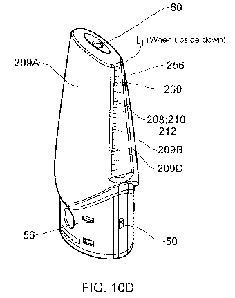
260.As illustrated in the cartridge shown in Figures 10C-10E, the portion 208
of the cartridge
200 may be located on at least one side surface(s) 2090;209D of the cartridge
200. In some
embodiments, the side surfaces 2090;209D may be inclined towards the outlet
60. In
Figures 10C-10E, and Figures 10F-10H, the portion 208 is located on two side
surfaces
2090;209D which are each located between the first, front, surface 209A; and
the second,
rear, surface 209B opposite the front surface 209B of the cartridge 200. The
portion 208 of
the cartridge in such embodiments as shown in Figures 10C-10E forms the first
wall portion
212 and comprises a pair of windows 210, such as one window 210 on each of the
side
surfaces 2090;209D, for viewing into the reservoir 31.
In such embodiments, the portion 208/each window 210 of the cartridge 200 may
extend
from a first position proximal the outlet 60 to a second position that is
proximal the vaporiser
40. In the embodiments shown in Figures 10C-10E and Figures 10F-10H, the
plurality of
markings 256 and the text indicators 260 are located on the first wall portion
212 of the
reservoir 31. By locating the portion 208 / window 210 proximal the outlet 60,
this allows the
user to more easily observe residual levels of aerosolisable material inside
the reservoir 31
when the cartridge 200 is orientated to have the outlet 60 facing downwards
(see for
instance an example residual level of aerosolisable material L1 as illustrated
in Figures 10D
and 10G, that is visible when such cartridges 200 are orientated to have the
outlet 60 facing
downwards, and when there is a residual level of aerosolisable material L1
left in the
reservoir 31).
Returning to the cartridge shown in Figure 10A, in accordance with some
embodiments of
cartridge 200, the aerosolisable-material-level observation means 205 may
comprise at least
one light source 260 for illuminating the contents of the reservoir 31. In
some embodiments,
the light source 260 may be located in the reservoir and/or attached to a wall
of the reservoir
31, as shown in Figure 10A. The light source is preferably electrically
powered, and in some
embodiments is operable to receive power from a power supply 16 of the control
unit 4 when
the cartridge 200 is coupled to the control unit 4 (for instance via the
contact electrodes 46).
Turning to the version of the cartridge 200 shown in Figures 11A-11C, in
accordance with
some embodiments of the cartridge 200, an optical property of the portion 208
of the
cartridge 200, or the first wall portion 212, may be operable to be varied by
the user of the
cartridge 200. In that way, an aerosolisable-material-level observation means
205 may be
22
CA 03152832 2022-02-28
WO 2021/038192
PCT/GB2020/051932
provided for selectively allowing a user to observe the level of aerosolisable
material 207
inside the reservoir 31 by varying the optical property of the portion 208;212
of the cartridge
200. In accordance with some embodiments, the optical property of the portion
of the
cartridge 200 may be operable to be varied upon supply of an electric current
to the portion
of the cartridge 200 (for instance in some embodiments via the contact
electrodes 46),
and/or varied in response to an electrical signal. In some embodiments, the
optical property
of the portion of the cartridge may be configured to be varied in response to
the pressing of a
button or switch 262, which may in some particular embodiments be located on
the cartridge
200, as shown in Figure 11A. Where an electrical supply is required for the
aerosolisable-
material-level observation means 205, such as the embodiments outlined above,
the
aerosolisable-material-level observation means 205 may in such embodiments be
operable
to receive power from the power supply 16 of the control unit 4 when the
cartridge 200 is
coupled to the control unit 4 (for instance via the contact electrodes 46).
The optical property which may be varied may, in some embodiments, be the
translucency
and/or the transparency of the portion 208;212 of the cartridge 200. In that
respect, in an
example operation, the portion of the cartridge 200 may be varied/switched
between a first
state in which the user cannot observe the level of aerosolisable material 207
inside the
reservoir 31, and a second state (for instance a second state where the
portion 208;212 is in
a more transparent/translucent configuration than when the portion 208;212 is
in the first
state) where the user can observe the level of aerosolisable material 207
inside the reservoir
31. A possible material for the portion 208;212 of the cartridge in such
embodiments is an
electrochromic material 260, which might in some particular embodiments
comprise an
electrochromic glass; electrochromic plastic; and/or electrochromic ink. For
such
embodiments, Figures 110 illustrates the portion 208;212 of the cartridge in
the first state in
which the user cannot observe the level of aerosolisable material 207 inside
the reservoir 31,
whereas Figure 11B illustrates the portion 208;212 of the cartridge in the
second state in
which the user can observe the level of aerosolisable material 207 inside the
reservoir 31.
Another modified version of the cartridge 200 in shown in Figures 12A-12B. As
shown in
these Figures, it is envisaged that in some embodiments of the cartridge 200,
the
aerosolisable-material-level observation means 205 may comprise at least one
contoured
surface 300 located on a surface of the cartridge 200 (including for instance,
but not
necessarily limited to, any one or combination of the first, front, surface
209A; the second,
rear, surface 209B opposite the front surface 209B; and/or the side surface(s)
2090;209D of
the cartridge 200 which are located between the front surface 209A and the
rear surface
209B). A function of the contoured surface 300, which is a surface that is not
23
CA 03152832 2022-02-28
WO 2021/038192
PCT/GB2020/051932
featureless/smooth, is to improve the visibility of the aerosolisable material
level 207 inside
the reservoir due to the interaction of light with the contoured surface.
In accordance with some embodiments, such as the embodiment shown in Figures
12A and
12B, a first contoured surface 301 may be located in the reservoir 31. As
shown in those
Figures, the contoured surface is not smooth, and is not featureless, and may
extend from
the first end 31A of the reservoir 31 to the second end 31B, opposite the
first end 31A, of the
reservoir 31. Depending on the embodiment, the first contoured surface 301
may, or may
not, extend around the entirety of a circumference of the reservoir 31. For
instance, in some
embodiments the first contoured surface 301 may extend around a half of a
circumference of
the reservoir 31.
In some particular embodiments where the reservoir 31 comprises an elliptical
cross section
206 comprising a major axis and a minor axis, the first contoured surface 301
located in the
reservoir 31 may in such embodiments be located at one or both intersections
of the elliptical
cross section 206 with the major axis. Similarly, in some embodiments, the
first contoured
surface 301 may not be located at one or both intersections of the elliptical
cross section 206
with the minor axis.
In accordance with some embodiments, a contoured surface 302 may be located on
an
outermost surface of the cartridge 200 (as shown in Figure 12A). The presence
of the
contoured surface 302 on the outermost surface of the cartridge 200 not only
provides a
user with a gripping means for better holding the cartridge 200, but also when
the outermost
surface is not opaque, improves the visibility of the aerosolisable material
level 207 inside
the reservoir 31 due to the interaction of light with the contoured surface
302. As required,
the contoured surface 302 may in some embodiments (as in the case of Figure
12A), or may
not in other embodiments, extend around the entirety of a circumference of the
outermost
surface of the cartridge 200. In some embodiments, the contoured surface 302
may extend
around a half of a circumference of the outermost surface of the cartridge
200.
In terms of the shape/contours of each contoured surface 301302, one or more
of the
contoured surfaces 301;302 in accordance with some embodiments may comprise a
plurality
of surface features, such as grooves. In some embodiments, one or more of the
contoured
surfaces 301302 may comprise a plurality of surface features in the form of
projections
and/or recesses 303. As noted above, the surface features from these contoured
surfaces
301302 improve the visibility of the aerosolisable material level 207 inside
the reservoir 31
due to the interaction of light with the contoured surface.
In relation to the contoured surfaces 301302, in some embodiments each such
contoured
surface 301;302 may be longer in a first (length) direction than in a second
(width) direction
24
CA 03152832 2022-02-28
WO 2021/038192
PCT/GB2020/051932
that is perpendicular to the first direction. In some embodiments, the first
direction of the
contoured surface may be parallel to the longitudinal axis L of the cartridge
200.
In accordance with some embodiments, the aerosolisable-material-level
observation means
may comprise a smooth surface 304 located on a surface of the cartridge 200,
such as a
surface located in the reservoir 31 and/or a surface located on an outermost
surface from
the cartridge 200. Where appropriate, these smooth surfaces may be polished.
In some
particular embodiments, the smooth surface 304 may be located on a first side
of the
reservoir 31, with a contoured surface 301 located on a second side, opposite
the first side,
of the reservoir 31. Figure 12A illustrates such a particular embodiment of
cartridge 200. In
that embodiment, the two opposing contoured/smooth surfaces 301;304 may
further improve
the visibility of the aerosolisable material level 207 inside the reservoir 31
due to the
interaction of light with the two surfaces 301;304. Furthermore, having only
one or more of
the sides of the reservoir that are contoured surfaces, as opposed to the
entirety of the sides
of the reservoir being contoured surfaces makes the cartridge 200 easier to
tool and
manufacture.
In some of the above embodiments, in terms of the materials used in the
cartridge 200, in
some embodiments the first wall portion 212 and/or the second wall portion 214
may
comprise/be made of plastic. In some embodiments, the first wall portion 212
may
comprise/be made of a material that is different from the material of the
second wall portion
214. Such embodiments may be made using a two-shot moulding technique, where
each of
the different materials are one shot of the two-shot moulding technique. While
this may
increase the cost, manufacturing complexity, and/or material used, one can
select an
appropriate material for each portion of the cartridge, to form an appropriate
aerosolisable-
material-level observation means 205 with the desired characteristics.
Alternatively, other
embodiments may use the same material for the first wall portion 210 and
second wall
portion 212. Such embodiments may be formed using a one-shot moulding
technique. .
In accordance with particular embodiments described above, the reservoir 31
and/or the
aerosolisable-material-level observation means 205 may be made of plastic. The
provision
of plastic for these parts of the cartridge 200 makes the cartridge 200
lightweight and easy to
manufacture.
Thus in accordance with certain embodiments of the disclosure, a cartridge for
an aerosol
provision system may generally comprise a housing part having a mouthpiece end
and an
interface end, wherein the mouthpiece end includes an aerosol outlet for the
cartridge and
the interface end includes an interface for coupling the cartridge to a
control unit. An air
channel wall (which may be formed by various components of the cartridge)
extends from an
CA 03152832 2022-02-28
WO 2021/038192
PCT/GB2020/051932
air inlet for the cartridge to the aerosol outlet via an aerosol generation
region in the vicinity
of a vaporiser. The cartridge has a reservoir within the housing part
containing aerosolisable
material for aerosolisation. The reservoir is defined by a region within the
housing part which
is outside the air channel and an end of the reservoir at the interface end of
the housing part
is sealed by a resilient plug comprising a base part and an outer wall,
wherein the outer wall
of the resilient plug forms a seal with an inner surface of the housing part.
Respective ends
of a aerosolisable material transport element pass through opening in the air
channel or into
the reservoir so as to convey aerosolisable material from the reservoir to the
vaporiser.
One aspect of some particular cartridge configurations in accordance with
certain
embodiments of the disclosure is the manner in which the resilient plug 44
provides a seal to
the housing part 32. In particular, in accordance with some example
implementations the
outer wall 102 of the resilient plug 44 which seals to the inner surface of
the housing part 32
to form the end of the aerosolisable material reservoir extends in direction
parallel to the
longitudinal axis of the cartridge to a position which is further from the
interface end of the
cartridge than the aerosolisable material transport element / vaporiser. That
is to say, the
ends of the aerosolisable material transport element extends into the
aerosolisable material
reservoir in a region which is surrounded by the outer sealing wall of the
resilient plug. Not
only does this help seal the reservoir against leakage, it allows the geometry
of the reservoir
in the region which supplies the aerosolisable material transport element with
aerosolisable
material to be governed by the geometry of the resilient plug. For example,
the radial
thickness of the reservoir in this region can readily be made smaller than the
radial thickness
in other longitudinal positions along the air channel, which can help trap
aerosolisable
material in the vicinity of the aerosolisable material transport element,
thereby helping to
reduce the risk of dry out for different orientations of the cartridge during
use.
The outer wall of the resilient plug may, for example, contact the inner
surface of the housing
part at locations over a distance of at least 5 mm, 6 mm, 7 mm, 8 mm, 9 mm and
10 mm in a
direction extending from the interface end to the mouthpiece end (i.e.
parallel to the
longitudinal axis). The outer wall of the resilient plug may be in contact
with the inner surface
of the housing over the majority of this distance, or the outer wall of the
resilient plug may
include a number of (e.g. four) circumferential ridges 140 to help improve
sealing. The
resilient plug may be slightly oversized relative to the opening in the
housing part so that it is
biased into slight compression. For example, for the implementation shown in
Figure 3B, the
interior width of the housing part into which the resilient plug is inserted
in the plane of this
figure is around 17.5 mm, whereas the corresponding width of the resilient
plug is around 18
mm, thereby placing the resilient plug into compression when inserted into the
housing part.
As can be most readily seen in Figures 5A to 5C, whereas the outer cross
section of the
26
CA 03152832 2022-02-28
WO 2021/038192
PCT/GB2020/051932
cartridge housing part is symmetric under a 180 rotation, the resilient plug
44 does not have
the same symmetry because it includes a flat 142 on one side to accommodate
the air
channel gap 76 provided by the double-walled section 74 of the housing part
(i.e. the
resilient plug is asymmetric in a plane perpendicular to a longitudinal axis
of the cartridge to
accommodate the double-walled section of the housing part).
In terms of the radial size / width of the reservoir in the annular region
where the
aerosolisable material transport element extends into the reservoir, a
distance between the
air channel wall and the outer wall of the resilient plug in this region may,
for example, be in
the range 3 mm to 8 mm. In the example cartridge discussed above which has a
generally
oval housing part and a generally circular air channel, it will be appreciated
the thickness of
the reservoir is different at different locations around the air channel. In
this example the
aerosolisable material transport element is arranged to extend into the
reservoir in the region
where it is widest in the axial direction, i.e. into the "lobes" of the oval
reservoir around the
air channel. The portions of the aerosolisable material transport element that
extend into the
reservoir may, for example, have a length, as measured from the interior of
the air channel
wall, in the range 2 mm to 8 mm, e.g. in the range 3 mm to 7 mm or in the
range 4 mm to 6
mm. The specific geometry in this regard (and for other aspects of the
configuration) may be
chosen having regard to a desired rate of aerosolisable material transport,
for example
having regard to the capillary strength of the aerosolisable material
transport element and
the viscosity of the aerosolisable material, and may be established for a
given cartridge
design through modelling or empirical testing.
Another aspect of some particular cartridge configurations in accordance with
certain
embodiments of the disclosure is the manner in which the air channel is routed
through the
cartridge, and in particular from the air inlet to the vicinity of the
vaporiser (the aerosol
generation region). In particular, whereas in a conventional cartridges an air
inlet is typically
provided at the interface end of the cartridge, in accordance with certain
embodiments of the
disclosure, an air inlet for the cartridge is located in a side wall of the
housing part at a
position which is further from the interface end than at least a part of the
resilient plug that
seals an end of the reservoir. Thus, the air channel in the cartridge is
initially routed from the
air inlet towards the interface end and bypasses the resilient plug before
changing direction
and entering the aerosol generation chamber through the resilient plug. This
can allow the
outer surface of the cartridge at the interface end, where it is closest to
the vaporiser, to be
closed, thereby helping to reduce the risk of leakage from the cartridge, both
in terms of
aerosolisable material coming through the openings in the air channel which is
not retained
by the aerosolisable material transport element in the air channel (e.g. due
to saturation /
agitation) or aerosolisable material that has being vaporised but condensed
back to
27
CA 03152832 2022-02-28
WO 2021/038192
PCT/GB2020/051932
aerosolisable material in the air channel during use. In some implementations,
a distance
from air inlet to the interface end of the housing part may be at least 5 mm,
6 mm, 7 mm, 8
mm, 9 mm or 10 mm.
In some example implementations an absorbent element, for example a portion of
sponge
material or a series of channels forming a capillary trap, may be provided
between the air
inlet and the aerosol generation chamber, for example in the region air
channel formed
between the base of the resilient plug and the end cap, to further help reduce
the risk of
leakage by absorbing aerosolisable material that forms in the air channel and
so helping
prevent the aerosolisable material travelling around the air channel through
the air inlet or
towards the aerosol outlet.
In some example implementations the air channel from the air inlet to the
aerosol outlet may
have its smallest cross-sectional area where it passes through the hole 106 in
the resilient
plug. That is to say, the hole in the resilient plug may be primarily
responsible for governing
the overall resistance to draw for the electronic cigarette.
Another aspect of some particular cartridge configurations in accordance with
certain
embodiments of the disclosure is the manner in which the dividing wall element
divides the
air reservoir into two regions, namely a main region above the dividing wall
(i.e. towards a
mouthpiece end of the cartridge) and a aerosolisable-material-supply region
below the
dividing wall (i.e. on the same side of the dividing wall as where the
aerosolisable material
transport element extends from the vaporiser into the reservoir). The dividing
wall includes
openings to govern the flow of aerosolisable material on the main region to
the aerosolisable
material supply region. The dividing wall can help retain aerosolisable
material in the
aerosolisable material supply region of the reservoir, example when the
electronic cigarette
is tilted through various orientations, which can help avoid dry out. The
dividing wall can also
conveniently provide a mechanical stop for the resilient plug to abut / press
against so as to
help correctly locate the resilient plug during assembly and maintain the
resilient plug in
slight compression between the dividing wall and the end cap when the
cartridge is
assembled.
In the example discussed above, the dividing wall is formed as a separate
element form the
housing part, wherein an inner surface of the housing part includes one or
more protrusions
arranged to contact the side of the dividing wall facing the mouthpiece end of
the cartridge to
locate the dividing wall along a longitudinal axis of the cartridge, but in
other examples the
dividing wall may be integrally formed with the housing part.
In the example discussed above the dividing wall is in the form of an annular
band around
the air channel and comprises four fluid communication openings 150 located in
respective
28
CA 03152832 2022-02-28
WO 2021/038192
PCT/GB2020/051932
quadrants of the band. However, more or fewer openings through the dividing
wall may be
provided in different implementations. Individual openings may, for example,
have an area of
between 4 mm2 and 15 mm2.
A combined area for the at least one openings as a fraction of the total area
of the dividing
wall exposed to aerosolisable material supply region of the reservoir region
may be, for
example, from 20% to 80%; 30% to 70% or 40% to 60%.
It will be appreciated that while the above description has focused on some
specific cartridge
configurations comprising a number of different features, cartridges in
accordance with other
embodiments of the disclosure may not include all these features. For example,
in some
implementations an air path generally of the kind discussed above, i.e. with
an air inlet which
is in a sidewall of the cartridge and closer to the mouthpiece end of the
cartridge than the
vaporiser, may be provided in a cartridge which does not include a resilient
plug with an
outer sealing wall which extends around the vaporiser and / or does not
include a dividing
wall element of the kind discussed above. Similarly, a cartridge which does
include a
resilient plug with an outer sealing wall which extends around the vaporiser
may have an air
inlet into the cartridge which is at the interface end of the cartridge, and
not in a sidewall, and
which may also not have a dividing wall element of the kind discussed above.
Furthermore,
a cartridge which does include a dividing wall element, might not include an
air inlet located
further from the interface end of the cartridge than the vaporiser and / or an
extended outer
sealing wall for a resilient plug as discussed above.
Thus, there has been described a cartridge for an aerosol provision system
comprising the
cartridge and a control unit, wherein the system comprises a vaporiser for
vaporising an
aerosolisable material, wherein the cartridge comprises: an air channel
extending from an air
inlet for the cartridge to an outlet via an aerosol generation region; a
reservoir for containing
aerosolisable material for aerosolising; wherein the cartridge further
comprises an
aerosolisable-material-level observation means for allowing a user to observe
a level of
aerosolisable material inside the reservoir.
There has also been described a cartridge 200 for an aerosol provision system
comprising
the cartridge 200 and a control unit 4 is provided. The cartridge 200
comprises an air
channel extending from an air inlet for the cartridge to an outlet via an
aerosol generation
region, and a reservoir 31 for containing aerosolisable material for
aerosolising. The system
comprises a vaporiser 40 for heating aerosolisable material from the reservoir
31 to generate
aerosol in the aerosol generation region, and the cartridge comprises an
aerosolisable-
material-level observation means for allowing a user to observe a level of
aerosolisable
material inside the reservoir. The aerosolisable-material-level observation
means may
29
CA 03152832 2022-02-28
WO 2021/038192
PCT/GB2020/051932
comprise at least one contoured surface 300 located on a surface of the
cartridge 200, such
as a surface located in the reservoir 31. The contoured surface 300 improves
the visibility of
the level of aerosolisable material 207 inside the reservoir due to the
interaction of light with
the contoured surface 300.
Also described is a cartridge 2;200 for an aerosol provision system 1
comprising the
cartridge 2;200 and a control unit 4, wherein the system comprises a vaporiser
for vaporising
an aerosolisable material. The cartridge 2;200 comprises an air channel
extending from an
air inlet 50 for the cartridge 2;200 to an outlet 60 via an aerosol generation
region, and a
reservoir 31 for containing aerosolisable material 207 for aerosolising. The
cartridge 2;200
further comprises an aerosolisable-material-level observation means 205 for
allowing a user
to observe a level of aerosolisable material 207 inside the reservoir 31. The
aerosolisable-
material-level observation means 205 may comprise a portion 208 of the
cartridge 2;200,
which may comprise a window 210 for viewing into the reservoir 31. The portion
208 of the
cartridge 2;200 may be located on a first side surface 2090 and a second side
surface 209D
of the cartridge 2;200, and/or might be located on a different surface
209A;209B of the
cartridge 2;200.
Also described are the embodiments as set out in the clauses at the end of
this specification.
While the above described embodiments have in some respects focussed on some
specific
example aerosol provision systems, it will be appreciated the same principles
can be applied
for aerosol provision systems using other technologies. That is to say, the
specific manner in
which various aspects of the aerosol provision system function, for example in
terms of the
underlying form of the vaporiser or vaporiser technology used are not directly
relevant to the
principles underlying the examples described herein.
In that respect, it will also be appreciated that various modifications may be
made to the
embodiments of aerosol provision system described herein. For instance,
although the
vaporiser 40 has been described in a number of the above embodiments as being
located in
the cartridge, it will be appreciated that in some embodiments the vaporiser
may be located
in the control unit of the aerosol provision system.
It will also be appreciated that the teachings herein, such as the
aerosolisable-material-level
observation means 205 (and any of its more specific features, such as the
contoured surface
300; the portion 208; the window 210; and/or the light source 260), may also
be applicable to
other forms of aerosol provision system 1 which do not expressly comprise a
cartridge 2;200
and a control unit 4. From the foregoing therefore, also provided herein may
be an aerosol
provision system comprising a vaporiser for vaporising an aerosolisable
material; an air
channel extending from an air inlet for the aerosol provision system to an
outlet via an
CA 03152832 2022-02-28
WO 2021/038192
PCT/GB2020/051932
aerosol generation region; a reservoir for containing an aerosolisable
material for
aerosolising; wherein the aerosol provision system further comprises an
aerosolisable-
material-level observation means for allowing a user to observe a level of
aerosolisable
material inside the reservoir. In accordance with such embodiments, it is
envisaged that any
of the features of the aerosolisable-material-level observation means 205,
such as it
comprising a contoured surface 300; the portion 208; the window 210, may form
part of the
aerosol provision system 1 itself, rather than as part of a cartridge 2;200
specifically.
In order to address various issues and advance the art, this disclosure shows
by way of
illustration various embodiments in which the claimed invention(s) may be
practiced. The
advantages and features of the disclosure are of a representative sample of
embodiments
only, and are not exhaustive and/or exclusive. They are presented only to
assist in
understanding and to teach the claimed invention(s). It is to be understood
that advantages,
embodiments, examples, functions, features, structures, and/or other aspects
of the
disclosure are not to be considered limitations on the disclosure as defined
by the claims or
limitations on equivalents to the claims, and that other embodiments may be
utilised and
modifications may be made without departing from the scope of the claims.
Various
embodiments may suitably comprise, consist of, or consist essentially of,
various
combinations of the disclosed elements, components, features, parts, steps,
means, etc.
other than those specifically described herein, and it will thus be
appreciated that features of
the dependent claims/clauses may be combined with features of the independent
claims/clauses
in combinations other than those explicitly set out in the claims/clauses. The
disclosure may
include other inventions not presently claimed, but which may be claimed in
future. In effect,
any combination of feature(s) from one set of clauses/claims many be combined
with any
other individual feature(s) from any of the remaining set of clauses/claims.
31
CA 03152832 2022-02-28
WO 2021/038192
PCT/GB2020/051932
First Set of Clauses
1. A cartridge for an aerosol provision system comprising the cartridge and
a control
unit, wherein the system comprises a vaporiser for vaporising an aerosolisable
material,
wherein the cartridge comprises:
an air channel extending from an air inlet for the cartridge to an outlet via
an aerosol
generation region;
a reservoir for containing an aerosolisable material for aerosolising;
wherein the cartridge further comprises an aerosolisable-material-level
observation
means for allowing a user to observe a level of aerosolisable material inside
the reservoir.
2. A cartridge according to clause 1, wherein the aerosolisable-material-
level
observation means comprises a portion of the cartridge.
3. A cartridge according to clause 2, wherein the cartridge comprises a
first surface, a
second surface, and a first side surface and a second side surface, wherein
the side
surfaces are located between the first surface and the second surface.
4. A cartridge according to clause 3, wherein the first side surface and
the second side
are inclined towards the outlet.
5. A cartridge according to clause 3 or 4, wherein the portion of the
cartridge is located
on at least one of the side surfaces.
6. A cartridge according to clause 5, wherein the portion of the cartridge
is located on
both the side surfaces.
7. A cartridge according to any of clauses 3-6, wherein the portion of the
cartridge is
located on the first surface.
8. A cartridge according to any of clauses 3-7, wherein the portion of the
cartridge is
located on the second surface.
9. A cartridge according to any of clauses 2-8, wherein the portion of the
cartridge is
located proximal the outlet.
32
CA 03152832 2022-02-28
WO 2021/038192
PCT/GB2020/051932
10. A cartridge according to any of clauses 2-9, wherein the portion of the
cartridge
comprises a window for viewing into the reservoir.
11. A cartridge according to any of clauses 2 to 10, wherein the portion of
the cartridge is
translucent.
12. A cartridge according to any of clauses 2-11, wherein the portion of
the cartridge is
transparent.
13. A cartridge according to any of clauses 2-12, wherein the portion of
the cartridge
forms a first wall portion of the reservoir, wherein the first wall portion
has a maximum
thickness which is no more than 1mm.
14. A cartridge according to any of clauses 2-13, wherein the portion of
the cartridge
forms a first wall portion of the reservoir, wherein the reservoir further
comprises a second
wall portion.
15. A cartridge according to clauses 13 or 14, wherein the first wall
portion defines a first
recess inside the reservoir.
16. A cartridge according to any of clauses 13-15, wherein the first wall
portion defines a
second recess on an outside surface of the cartridge.
17. A cartridge according to clause 14-16, wherein the first wall portion
is more
transparent than the transparency of the second wall portion.
18. A cartridge according to any of clauses 14-17, wherein the first wall
portion is more
translucent than the translucency of the second wall portion.
19. A cartridge according to any of clauses 14-18, wherein the first wall
portion
comprises a first concentration of coloured pigment, and the second wall
portion comprises a
second concentration of coloured pigment, wherein the first concentration is
less than the
second concentration.
20. A cartridge according to clause 19, wherein the first concentration of
coloured
pigment is no more than 1g of pigment per 1kg of the first wall portion.
33
CA 03152832 2022-02-28
WO 2021/038192
PCT/GB2020/051932
21. A cartridge according to clause 19 or 20, wherein the first
concentration of coloured
pigment is no more than 0.9g of pigment per 1kg of the first wall portion.
22. A cartridge according to any of clauses 19-21, wherein the first
concentration of
coloured pigment is no more than 0.85g of pigment per 1kg of the first wall
portion.
23. A cartridge according to any of clauses 19-22, wherein the second
concentration of
coloured pigment is more than 1g of pigment per 1kg of the second wall
portion.
24. A cartridge according to any of clauses 19-23, wherein the second
concentration of
coloured pigment is more than 1.3g of pigment per 1kg of the second wall
portion.
25. A cartridge according to any of clauses 19-24, wherein the second
concentration of
coloured pigment is more than 1.6g of pigment per 1kg of the second wall
portion.
26. A cartridge according to any of clauses 13-25, wherein the first wall
portion is made
of plastic.
27. A cartridge according to any of clauses 14-26, wherein the second wall
portion is
made of plastic.
28. A cartridge according to any of clauses 14-27, wherein the first wall
portion has a
maximum thickness which is less than the maximum thickness of the second wall
portion.
29. A cartridge according to any of clauses 14-28, wherein the first wall
portion
comprises a material that is different from the material of the second wall
portion.
30. A cartridge according to any preceding clause, further comprising an
aerosol outlet
tube, extending between the aerosol generating region and the outlet, for
directing aerosol
generated in the aerosol generating region through to the outlet.
31. A cartridge according to clause 30, wherein the reservoir extends
around the aerosol
outlet tube.
32. A cartridge according to any preceding clause, wherein the reservoir is
annular.
34
CA 03152832 2022-02-28
WO 2021/038192
PCT/GB2020/051932
33. A cartridge according to any preceding clause, wherein the reservoir
contains the
aerosolisable material for aerosolising.
34. A cartridge according to any preceding clause, wherein the vaporiser is
located in the
cartridge.
35. An aerosol provision system comprising the cartridge of any preceding
clause and a
control unit, wherein the control unit comprises a cartridge receiving section
that includes an
interface arranged to cooperatively engage with the cartridge so as to
releasably couple the
cartridge to the control unit, wherein the control unit further comprises a
power supply and
control circuitry.
36. An aerosol provision system according to clause 35, wherein the control
circuitry is
configured to selective supply power from the power supply to the vaporiser
located in the
cartridge via their cooperatively engaging interfaces.
CA 03152832 2022-02-28
WO 2021/038192
PCT/GB2020/051932
Second Set of Clauses
1. A cartridge for an aerosol provision system comprising the cartridge and
a control
unit, wherein the system comprises a vaporiser for vaporising an aerosolisable
material,
wherein the cartridge comprises:
an air channel extending from an air inlet for the cartridge to an outlet via
an aerosol
generation region;
a reservoir for containing aerosolisable material for aerosolising;
wherein the cartridge further comprises an aerosolisable-material-level
observation
means for allowing a user to observe a level of aerosolisable material inside
the reservoir.
2. A cartridge according to clause 1, wherein the cartridge further
comprises a covering
means for inhibiting the visibility of a portion of the cartridge by the user.
3. A cartridge according to clause 2, wherein the covering means comprises
an opaque
sheet of material affixed to a surface of the cartridge.
4. A cartridge according to clause 3, wherein the sheet of material is
a label.
5. A cartridge according to any of clauses 2-4, wherein the covering means
comprises
an opaque material forming part of the cartridge.
6. A cartridge according to clause 5, wherein the opaque material is an
opaque plastic.
7. A cartridge according to any of clauses 2-6, wherein the portion
comprises the
vaporiser.
8. A cartridge according to any of clauses 2-7, wherein the portion
comprises the
aerosol generation region.
9. A cartridge according to any of clauses 2-8, wherein the portion
comprises the air
channel.
10. A cartridge according to any preceding clause, wherein the reservoir is
made of
plastic.
36
CA 03152832 2022-02-28
WO 2021/038192
PCT/GB2020/051932
11. A cartridge according to any preceding clause, wherein the
aerosolisable-material-
level observation means further comprises a portion of the cartridge.
12. A cartridge according to clause 11, wherein the portion of the
cartridge is translucent.
13. A cartridge according to clause 11 or 12, wherein the portion of the
cartridge is
transparent.
14. A cartridge according to any preceding clause, further comprising an
aerosol outlet
tube, extending between the aerosol generating region and the outlet, for
directing aerosol
generated in the aerosol generating region through to the outlet.
15. A cartridge according to clause 14, wherein the reservoir extends
around the aerosol
outlet tube.
16. A cartridge according to any preceding clause, wherein the reservoir is
annular.
17. A cartridge according to any preceding clause, wherein the reservoir
contains the
aerosolisable material for aerosolising.
18. A cartridge according to any preceding clause, wherein the vaporiser is
located in the
cartridge.
19. An aerosol provision system comprising the cartridge of any preceding
clause and a
control unit, wherein the control unit comprises a cartridge receiving section
that includes an
interface arranged to cooperatively engage with the cartridge so as to
releasably couple the
cartridge to the control unit, wherein the control unit further comprises a
power supply and
control circuitry.
20. An aerosol provision system according to clause 19, wherein the control
circuitry is
configured to selective supply power from the power supply to the vaporiser
located in the
cartridge via their cooperatively engaging interfaces.
37
CA 03152832 2022-02-28
WO 2021/038192
PCT/GB2020/051932
Third Set of Clauses
1. A cartridge for an aerosol provision system comprising the cartridge and
a control
unit, wherein the system comprises a vaporiser for vaporising an aerosolisable
material,
wherein the cartridge comprises:
an air channel extending from an air inlet for the cartridge to an outlet via
an aerosol
generation region;
a reservoir for containing aerosolisable material for aerosolising;
wherein the cartridge further comprises an aerosolisable-material-level
observation
means for allowing a user to observe a level of aerosolisable material inside
the reservoir.
2. A cartridge according to clause 1, wherein the aerosolisable-material-
level
observation means comprises a portion of the cartridge.
3. A cartridge according to clause 2, wherein the portion of the cartridge
comprises a
window for viewing into the reservoir.
4. A cartridge according to any of clauses 2-3, wherein an optical property
of the portion
of the cartridge is operable to be varied by the user of the cartridge.
5. A cartridge according to any of clauses 2-4, wherein an optical property
of the portion
of the cartridge is operable to be varied upon supply of an electric current
to the portion of
the cartridge.
6. A cartridge according to clause 4 or 5, wherein the optical property is
the
translucency of the portion of the cartridge.
7. A cartridge according to any of clauses 4-6, wherein the optical
property is the
transparency of the portion of the cartridge.
8. A cartridge according to any of clauses 4-7, wherein the optical
property of the
portion of the cartridge is configured to be varied in response to an
electrical signal.
9. A cartridge according to any of clauses 4-8, wherein the optical
property of the
portion of the cartridge is configured to be varied in response to the
pressing of a button or
switch.
38
CA 03152832 2022-02-28
WO 2021/038192
PCT/GB2020/051932
10. A cartridge according to any clause 9, wherein the button or switch is
located on the
cartridge.
11. A cartridge according to any of clauses 2-10, wherein the portion of
the cartridge
comprises an electrochromic material.
12. A cartridge according to clause 11, wherein the electrochromic material
comprises
electrochromic glass.
13. A cartridge according to clause 11 or 12, wherein the electrochromic
material
comprises electrochromic plastic.
14. A cartridge according to any of clauses 11-13, wherein the
electrochromic material
comprises electrochromic ink.
15. A cartridge according to any preceding clause, further comprising an
aerosol outlet
tube, extending between the aerosol generating region and the outlet, for
directing aerosol
generated in the aerosol generating region through to the outlet.
16. A cartridge according to clause 15, wherein the reservoir extends
around the aerosol
outlet tube.
17. A cartridge according to any preceding clause, wherein the reservoir
is annular.
18. A cartridge according to any preceding clause, wherein the reservoir
contains the
aerosolisable material for aerosolising.
19. A cartridge according to any preceding clause, wherein the vaporiser is
located in the
cartridge.
20. An aerosol provision system comprising the cartridge of any preceding
clause and a
control unit, wherein the control unit comprises a cartridge receiving section
that includes an
interface arranged to cooperatively engage with the cartridge so as to
releasably couple the
cartridge to the control unit, wherein the control unit further comprises a
power supply and
control circuitry.
39
CA 03152832 2022-02-28
WO 2021/038192
PCT/GB2020/051932
21. An aerosol provision system according to clause 20, wherein the control
circuitry is
configured to selective supply power from the power supply to the vaporiser
located in the
cartridge via their cooperatively engaging interfaces.
22. An aerosol provision system according to clause 20 or 21, wherein the
aerosolisable-
material-level observation means is operable to receive power from the power
supply of the
control unit when the cartridge is coupled to the control unit.
CA 03152832 2022-02-28
WO 2021/038192
PCT/GB2020/051932
Fourth Set of Clauses
1. A cartridge for an aerosol provision system comprising the cartridge and
a control
unit, wherein the system comprises a vaporiser for vaporising an aerosolisable
material,
wherein the cartridge comprises:
an air channel extending from an air inlet for the cartridge to an outlet via
an aerosol
generation region;
a reservoir for containing aerosolisable material for aerosolising;
wherein the cartridge further comprises an aerosolisable-material-level
observation
means for allowing a user to observe a level of aerosolisable material inside
the reservoir.
2. A cartridge according to clause 1, wherein the aerosolisable-material-
level
observation means comprises a portion of the cartridge.
3. A cartridge according to clause 2, wherein the portion of the cartridge
comprises a
first window for viewing into the reservoir.
4. A cartridge according to clause 3, wherein the portion of the cartridge
comprises a
second window for allowing light into the reservoir.
5. A cartridge according to clause 4, wherein the second window has a
different shape
than the shape of the first window.
6. A cartridge according to clause 4 or 5, wherein the first window is
located on a first
side of the reservoir, and the second window is located on a second side,
opposite the first
side, of the reservoir.
7. A cartridge according to any of clauses 3-6, wherein each window has a
maximum
dimension of no more than 30mm, preferably no more than 20mm, and more
preferably no
more than 10mm.
8. A cartridge according to any of clauses 3-7, wherein the first window is
elongate.
9. A cartridge according to any of clauses 2-8, wherein the portion of the
cartridge is
translucent.
41
CA 03152832 2022-02-28
WO 2021/038192
PCT/GB2020/051932
10. A cartridge according to any of clauses 2-9, wherein the portion of the
cartridge is
transparent.
11. A cartridge according to any of clauses 2-10, wherein the portion of
the cartridge
forms a first wall portion of the reservoir, wherein the first wall portion
has a maximum
thickness which is no more than 1mm.
12. A cartridge according to any of clauses 2-11, wherein the portion of
the cartridge
forms a first wall portion of the reservoir, wherein the reservoir further
comprises a second
wall portion.
13. A cartridge according to clause 11 or 12, wherein the first wall
portion defines a first
recess inside the reservoir.
14. A cartridge according any of clauses 11-13, wherein the first wall
portion defines a
second recess on an outside surface of the cartridge.
15. A cartridge according to any of clauses 12-15, wherein the first wall
portion is more
transparent than the transparency of the second wall portion.
16. A cartridge according to any of clauses 12-15, wherein the first wall
portion is more
translucent than the translucency of the second wall portion.
17. A cartridge according to any of clauses 12-16, wherein the first wall
portion has a
maximum thickness which is less than the maximum thickness of the second wall
portion.
18. A cartridge according to any of clauses 12-17, wherein the first wall
portion
comprises a material that is different from the material of the second wall
portion.
19. A cartridge according to any preceding clause, further comprising an
aerosol outlet
tube, extending between the aerosol generating region and the outlet, for
directing aerosol
generated in the aerosol generating region through to the outlet.
20. A cartridge according to clause 19, wherein the reservoir extends
around the aerosol
outlet tube.
21. A cartridge according to any preceding clause, wherein the reservoir is
annular.
42
CA 03152832 2022-02-28
WO 2021/038192
PCT/GB2020/051932
22. A cartridge according to any preceding clause, wherein the reservoir
contains the
aerosolisable material for aerosolising.
23. A cartridge according to any preceding clause, wherein the vaporiser is
located in the
cartridge.
24. An aerosol provision system comprising the cartridge of any preceding
clause and a
control unit, wherein the control unit comprises a cartridge receiving section
that includes an
interface arranged to cooperatively engage with the cartridge so as to
releasably couple the
cartridge to the control unit, wherein the control unit further comprises a
power supply and
control circuitry.
25. An aerosol provision system according to clause 24, wherein the control
circuitry is
configured to selective supply power from the power supply to the vaporiser
located in the
cartridge via their cooperatively engaging interfaces.
43
CA 03152832 2022-02-28
WO 2021/038192
PCT/GB2020/051932
Fifth Set of Clauses
1. A cartridge for an aerosol provision system comprising the cartridge and
a control
unit, wherein the system comprises a vaporiser for vaporising an aerosolisable
material,
wherein the cartridge comprises:
an air channel extending from an air inlet for the cartridge to an outlet via
an aerosol
generation region;
a reservoir for containing aerosolisable material for aerosolising;
wherein the cartridge further comprises an aerosolisable-material-level
observation
means for allowing a user to observe a level of aerosolisable material inside
the reservoir.
2. A cartridge according to any preceding clause, wherein the aerosolisable-
material-
level observation means is located on a wall of the reservoir.
3. A cartridge according to any preceding clause, wherein the aerosolisable-
material-
level observation means comprises a plurality of markings on the cartridge for
allowing the
user to gauge the level of aerosolisable material inside the reservoir against
these plurality of
markings.
4. A cartridge according to clause 3, wherein the plurality of markings
comprise a
plurality of parallel lines.
5. A cartridge according to clause 3 or 4, wherein the plurality of
markings is recessed
into a surface of the cartridge.
6. A cartridge according to any of clauses 3-5, wherein the plurality of
markings project
from a surface of the cartridge.
7. A cartridge according to any of clauses 3-6, wherein the plurality of
markings project
.. from a surface of the reservoir.
8. A cartridge according to any of clauses 3-7, wherein the plurality of
markings are
opaque.
9. A cartridge according to any of clauses 3-8, wherein the plurality of
markings is
surrounded by a portion of the cartridge that is transparent.
44
CA 03152832 2022-02-28
WO 2021/038192
PCT/GB2020/051932
10. A cartridge according to any of clauses 3-9, wherein the plurality of
markings is
surrounded by a portion of the cartridge that is translucent.
11. A cartridge according to clause 9 or 10, wherein the portion of the
cartridge is made
of plastic.
12. A cartridge according to any of clauses 3-11, wherein the plurality of
markings are
located in a first wall portion of the reservoir, wherein the plurality of
markings project into the
reservoir.
13. A cartridge according to any of clauses 2-12, wherein the plurality of
markings
comprise text indicators for gauging the level of aerosolisable material
inside the reservoir.
14. A cartridge according to clause 13, wherein the text indicators
comprise a plurality of
percentage amounts between 0% - 100%.
15. A cartridge according to any of clauses 13-14, wherein the text
indicators comprise a
plurality of fractions between zero and one.
16. A cartridge according to any of clauses 13-15, wherein the text
indicators comprise a
plurality of volumetric amounts in imperial units.
17. A cartridge according to any of clauses 13-16, wherein the text
indicators comprise a
plurality of volumetric amounts in metric units.
18. A cartridge according to any of clauses 2-17, wherein the plurality of
markings have a
combined maximum dimension of no more than 30mm.
19. A cartridge according to any preceding clause, wherein the reservoir
contains the
aerosolisable material for aerosolising.
20. A cartridge according to any preceding clause, wherein the
aerosolisable-material-
level observation means comprises a light source for illuminating the contents
of the
reservoir.
21. A cartridge according to clause 20, wherein the light source is
electrically powered.
CA 03152832 2022-02-28
WO 2021/038192
PCT/GB2020/051932
22. A cartridge according to clause 20 or 21, wherein the light source is
located in the
reservoir.
23. A cartridge according to any of clauses 20-22, wherein the light source
is attached to
a wall of the reservoir.
24. A cartridge according to any preceding clause, further comprising an
aerosol outlet
tube, extending between the aerosol generating region and the outlet, for
directing aerosol
generated in the aerosol generating region through to the outlet.
25. A cartridge according to clause 24, wherein the reservoir extends
around the aerosol
outlet tube.
26. A cartridge according to any preceding clause, wherein the reservoir is
annular.
27. A cartridge according to any preceding clause, wherein the vaporiser is
located in the
cartridge.
28. An aerosol provision system comprising the cartridge of any preceding
clause and a
control unit, wherein the control unit comprises a cartridge receiving section
that includes an
interface arranged to cooperatively engage with the cartridge so as to
releasably couple the
cartridge to the control unit, wherein the control unit further comprises a
power supply and
control circuitry.
29. An aerosol provision system according to clause 28, wherein the control
circuitry is
configured to selective supply power from the power supply to the vaporiser
located in the
cartridge via their cooperatively engaging interfaces.
30. An aerosol provision system according to clause 28 or 29, wherein the
aerosolisable-
material-level observation means is operable to receive power from the power
supply of the
control unit when the cartridge is coupled to the control unit.
31. An aerosol provision system according to any of clause 28-30, when
further
dependent on any of clauses 20-23, wherein the light source is operable to
receive power
from the power supply of the control unit when the cartridge is coupled to the
control unit.
46
CA 03152832 2022-02-28
WO 2021/038192
PCT/GB2020/051932
32. A method of observing the level of aerosolisable material inside a
reservoir from a
cartridge for an aerosol provision system, wherein the cartridge comprises:
an aerosol outlet;
an air channel extending from an air inlet for the cartridge to the aerosol
outlet via an
aerosol generation region; and
an aerosolisable-material-level observation means for allowing a user to
observe a
level of aerosolisable material inside the reservoir; wherein the method
comprises:
using the aerosolisable-material-level observation means to observe the level
of
aerosolisable material inside the reservoir.
33. A method according to clause 32, wherein the cartridge further
comprises:
a reservoir within the housing part containing aerosolisable material for
aerosolising;
and
an aerosolisable material transport element for transporting aerosolisable
material
from the reservoir to a vaporiser;
wherein the method further comprises passing aerosolisable material from the
reservoir via the aerosolisable material transport element, and forming
aerosol inside the
aerosol generating region using the vaporiser.
47
CA 03152832 2022-02-28
WO 2021/038192
PCT/GB2020/051932
Consistory Set of Clauses
1. A cartridge for an aerosol provision system comprising the cartridge and
a control
unit, wherein the system comprises a vaporiser for vaporising an aerosolisable
material,
wherein the cartridge comprises:
an air channel extending from an air inlet for the cartridge to an outlet via
an aerosol
generation region;
a reservoir for containing aerosolisable material for aerosolising;
wherein the cartridge further comprises an aerosolisable-material-level
observation
means for allowing a user to observe a level of aerosolisable material inside
the reservoir.
2. A cartridge according to clause 1, wherein the aerosolisable-material-
level
observation means comprises at least one contoured surface located on a
surface of the
cartridge.
3. A cartridge according to clause 2, wherein the cartridge comprises a
first surface, a
second surface, and a first side surface and a second side surface, wherein
the side
surfaces are located between the first surface and the second surface.
4. A cartridge according to clause 3, wherein the contoured surface is
located on at
least one of the side surfaces.
5. A cartridge according to clause 4, wherein the contoured surface is
located on both
the side surfaces.
6. A cartridge according to any of clauses 3-5, wherein the contoured
surface is located
on the first surface.
7. A cartridge according to any of clauses 3-6, wherein the contoured
surface is located
on the second surface.
8. A cartridge according to any of clauses 2-7, wherein the contoured
surface is located
proximal the outlet.
9. A cartridge according to any of clauses 2-8, wherein the contoured
surface is located
in the reservoir.
48
CA 03152832 2022-02-28
WO 2021/038192
PCT/GB2020/051932
10. A cartridge according to clause 9, wherein the reservoir comprises
an elliptical cross
section comprising a major axis and a minor axis, wherein the contoured
surface is located
at an intersection of the elliptical cross section with the major axis.
11. A cartridge according to clause 10, wherein the contoured surface is
not located at
an intersection of the elliptical cross section with the minor axis.
12. A cartridge according to any of clauses 2-11, wherein the contoured
surface extends
from a first end of the reservoir to a second end, opposite the first end, of
the reservoir.
13. A cartridge according to any of clauses 2-12, wherein the contoured
surface does not
extend around the entirety of a circumference of the reservoir.
14. A cartridge according to any of clauses 2-13, wherein the contoured
surface is
located on an outermost surface of the cartridge.
15 A cartridge according to clause 14, wherein the contoured surface
does not extend
around the entirety of a circumference of the outermost surface of the
cartridge.
16. A cartridge according to any of clauses 2-16, wherein the contoured
surface
comprises a plurality of grooves.
17. A cartridge according to any of clauses 2-16, wherein the contoured
surface
comprises a plurality of projections and/or recesses.
18. A cartridge according to any preceding clause, wherein the
aerosolisable-material-
level observation means comprises a smooth surface located on a surface of the
cartridge.
19. A cartridge according to clause 18, wherein the smooth surface is
located in the
reservoir.
20. A cartridge according to clause 18 or 19, wherein the smooth surface is
located on
an outermost surface from the cartridge.
21. A cartridge according to any of preceding clause, wherein the
aerosolisable-material-
level observation means comprises a smooth surface inside the reservoir, and a
contoured
surface inside the reservoir.
49
CA 03152832 2022-02-28
WO 2021/038192
PCT/GB2020/051932
22. A cartridge according to clause21, wherein the smooth surface is
located on a first
side of the reservoir, and the contoured surface is located on a second side,
opposite the
first side, of the reservoir.
23. A cartridge according to any of clauses 18-22, wherein the smooth
surface is
polished.
24. A cartridge according to any preceding clause, wherein the reservoir is
made of
plastic.
25. A cartridge according to any preceding clause, wherein the
aerosolisable-material-
level observation means is made of plastic.
26. A cartridge according to any preceding clause, wherein the
aerosolisable-material-
level observation means comprises a portion of the cartridge.
27. A cartridge according to clause 26, wherein the portion of the
cartridge is translucent.
28. A cartridge according to clause 26 or 27, wherein the portion of the
cartridge is
transparent.
29. A cartridge according to any preceding clause, further comprising an
aerosol outlet
tube, extending between the aerosol generating region and the outlet, for
directing aerosol
generated in the aerosol generating region through to the outlet.
30. A cartridge according to clause 29, wherein the reservoir extends
around the aerosol
outlet tube.
31. A cartridge according to any preceding clause, wherein the reservoir is
annular.
32. A cartridge according to any preceding clause, wherein the reservoir
comprises a first
end which is proximal the outlet of the cartridge, and a second end which is
proximal the
vaporiser.
33. A cartridge according to any preceding clause, wherein the reservoir
comprises an
elliptical cross section.
CA 03152832 2022-02-28
WO 2021/038192
PCT/GB2020/051932
34. A cartridge according to any preceding clause, wherein the reservoir
contains the
aerosolisable material for aerosolising.
35. A cartridge according to any preceding clause, wherein the vaporiser is
located in the
cartridge.
36. An aerosol provision system comprising the cartridge of any preceding
clause and a
control unit, wherein the control unit comprises a cartridge receiving section
that includes an
interface arranged to cooperatively engage with the cartridge so as to
releasably couple the
cartridge to the control unit, wherein the control unit further comprises a
power supply and
control circuitry.
37. An aerosol provision system according to clause 36, wherein the control
circuitry is
configured to selective supply power from the power supply to the vaporiser
located in the
cartridge via their cooperatively engaging interfaces.
51