Note : Les descriptions sont présentées dans la langue officielle dans laquelle elles ont été soumises.
WO 2021/071407
PCT/SE2020/050939
A DEVICE FOR SUPPORTING A LOAD
TECHNICAL FIELD
The disclosure relates to a device for supporting a load comprising a fixed
lower
platform, a movable upper platform and at least three limbs interconnecting
the fixed
.5 platform and the movable upper platform.
BACKGROUND
Devices that are used to hold, move, and position a workpiece or an object are
useful
in several settings such as within manufacturing, machining, or industrial
processes.
It is used widely in aerospace and defence, automotive, transportation and
machine
tool technology. Devices used to hold, move and position workpieces and
objects
require accuracy, robustness and stability, to allow them to hold, move and
position
workpieces and objects of different sizes and weights without damaging the
device or
the quality of the task of the device.
It is known in the art to provide devices that perform these operations. Such
devices
is usually have an operating area adapted to hold, move, and position
workpieces and
objects. Further they usually comprise a plurality of limbs that are pivotably
movable
in relation to the operating area allowing the device to change position.
Devices within this technical area usually have one or several actuating
devices in
order for the device to be able to move within different positions and
directions. A
zo disadvantage of the prior art is that they may fail to provide
satisfactory performance
when being under high force or pressure. A further disadvantage of the prior
art is
that they fail to consistently provide stability to the device while
maintaining flexibility.
A previously known device is disclosed in US20140263883A1, which discloses a
tool
holder mounted to a platform and comprises a plurality of legs extending from
25 respective positions on the platform for connecting the platform to
respective
positions on the workpiece. Each leg has a first joint system at its platform
end.
Further, the tool holder is configured to allow free movement of the
respective leg. A
problem with this disclosure is that the free movement of the legs may hamper
the
stability of the device.
1
CA 03152926 2022-3-29
WO 2021/071407
PCT/SE2020/050939
Thus, even though the prior art fulfils certain requirements related to
devices there is
still a need for further improvements.
SUMMARY
It is therefore an object of the present disclosure to provide a device which
alleviates
all or at least part of the drawbacks associated with presently known
solutions.
This object is achieved by means of providing a device as defined in the
appended
claims
The present disclosure is at least partly based on the insight that by
providing
alternating revolute and prismatic joints the device will be more robust.
in In accordance with the invention there is provided a device according to
claim 1.
The present disclosure provides a machine comprising;
a fixed lower platform having a first connecting area;
a movable upper platform having an operating area and a second connecting
area;
at least three limbs, each limb comprising a lower section, an upper section
and an intermediate section between said lower section and said upper section;
each one of the limbs interconnects said fixed lower platform and said movable
upper platform by joining said first connecting area and said second
connecting
area, the lower section of each limb comprises a first part of a first
prismatic joint
arranged for movement along a first axis, and the first connecting area
comprises
a cooperating second part of said first prismatic joint. Further, the lower
section of
each limb further comprises a first revolute joint arranged for movement
around a
second axis. The intermediate section of each limb comprises a second
prismatic
joint extendable along a third axis defined by the axis of extension of the
intermediate section of the limb, and the upper section of each limb comprises
a
second revolute joint for rotation around a fourth axis. Each limb is
pivotably
movable relative to the movable upper platform and each of the limbs comprise
an actuation arrangement for moving the movable upper platform relative to the
fixed lower platform. Further, each limb comprises an actuation arrangement
for
moving the upper platform relative the lower platform. The intermediate
section of
2
CA 03152926 2022-3-29
WO 2021/071407
PCT/SE2020/050939
each limb comprises an upper and lower body, a first support structure extends
from the lower section of the limb to the upper body, traversing the lower
body.
The intermediate section of each limb comprises a second support structure
which extends from the upper section to the lower body, traversing the upper
s
body. The actuation arrangement is arranged
allowing for slidable motion of the
upper body relative the lower body. The actuation arrangement further
comprises
a device for actuating the actuation arrangement.
A benefit of having a device with four joints, where every other joint is
prismatic and
in every other joint is revolute is that it may allow for more accurate and
fast
movements from the device. Further, the benefit of having a first prismatic
joint that
has a first part on the limb and a second cooperating part on the fixed lower
platform
is that it constraints the limb movement relative to the fixed lower platform
which
allows for a more robust and stable construction. The upper and lower bodies
1.5 increase the rigidity and ability of the device to support greater
loads on the movable
platform.
The movable upper platform may be parallel to said fixed lower platform
independently of its position. This also provides the benefit of a more robust
and
stable construction.
20 The first part of said first prismatic joint may comprise a bearing
carriage. Further the
second part of said first prismatic joint may comprise a rail arrangement
provided on
the first connecting area. Furthermore, the first part of the first prismatic
joint may be
slidably attached to the rail arrangement, allowing for linear motion along
said rail
arrangement.
25 An advantage of having a bearing carriage slidably attached to a rail
arrangement is
that it allows for a low friction linear slidable movement. Accordingly, this
leads to
stability of the device while maintaining flexibility in location of the
position of the
upper platform.
3
CA 03152926 2022-3-29
WO 2021/071407
PCT/SE2020/050939
The rail arrangement may comprise at least three straight rail tracks, wherein
said rail
arrangement may form a polygonal shape, wherein each bearing carriage is
slidably
attached to a respective rail track.
A benefit of having several rail tracks forming a polygonal shape is that it
allows for
the first prismatic joint to have a larger motion area. A further advantage is
that the
device is more stable and robust.
The limbs may have a tapered extension from said fixed lower platform to said
movable upper platform. A benefit of this is that it may allow for more
stability to
pressuring forces on the movable upper platform. Accordingly, there is a less
chance
in that the limbs may be damaged.
The movable upper platform may only have three translational degrees of
freedom.
An advantage of this is that it allows for flexibility of the device while
maintaining
stability.
The second prismatic joint may be telescopically extendable. This may allow
for the
second prismatic joint to extend with low friction.
The second prismatic joint in said intermediate section of each of said at
least three
limbs may further comprise a lower body and an upper body, wherein a first
support
structure extend from said lower section to said upper body, traversing said
lower
body, wherein a second support structure extend from said upper section to
said
zo lower body, traversing said upper body, wherein said actuation
arrangement is
attached to at least a part of one of said upper body or lower body, allowing
for a
slidable motion. A benefit of having support structures extending in the limb
is that
they may prevent the limbs from rotating when under pressure and motion.
Further,
they may increase the stability of the limbs by support the structure. It
should be
understood that this is just one exemplary embodiment, and that other
exemplary
embodiments with different configurations of the limbs are conceivable. For
instance,
the lower body and upper body may, in other exemplary embodiments be omitted.
Likewise, the number of support structures extending in the limbs may be
adapted as
desired, or may be omitted, etc.
4
CA 03152926 2022-3-29
WO 2021/071407
PCT/SE2020/050939
One of said first or second support structure may form a part of the actuation
arrangement, the actuation arrangement may further comprise a motor for
driving
said one support structure linearly. A benefit of this is that with the help
of one
actuation arrangement on each limb, all the prismatic joints may be utilized
and the
device may operate according to its function.
The second prismatic joint in said intermediate section of each of said at
least three
limbs may further comprise a lower body and an upper body. Further the
actuation
arrangement may comprise a shaft, extending from the lower section to at least
said
upper body. The shaft is linearly guided by a motor in the actuation
arrangement,
in allowing for slidable motion. Accordingly, the shaft of each limb may
steer the
movement of the movable upper platform in relation to the fixed lower
platform. An
advantage of having a shaft steering the movements is that it allows for more
stability
when trying to extend under pressure.
A method for supporting a load is also provided.
Further advantageous embodiments are disclosed in the appended and dependent
patent claims.
BRIEF DESCRIPTION OF DRAWINGS
Further objects, features, and advantages of embodiments of the disclosure
will
appear from the following detailed description, reference being made to the
zo accompanying drawings, in which:
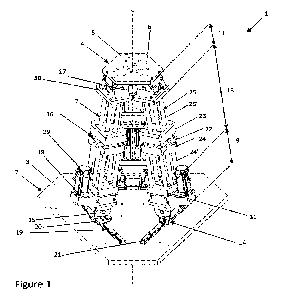
FIGURE 1 Depicts a perspective view of at least one exemplary embodiment of
the
device.
FIGURE 2 Depicts a perspective view of a part of a limb, which may be used
with the
embodiment of Figure 1.
FIGURE 3 Depicts a front view of a part of the limb in Figure 2.
FIGURE 4 Depicts a perspective view of a fixed lower platform and a first
prismatic
joint and a first revolute joint.
FIGURE 5 Depicts another perspective view of the device.
FIGURE 6 Depicts a perspective view of a part of a limb which may be used with
the
embodiment of Figure 1.
5
CA 03152926 2022-3-29
WO 2021/071407
PCT/SE2020/050939
DETAILED DESCRIPTION
In the following detailed description, some embodiments of the present
disclosure will
be described. However, it is to be understood that features of the different
embodiments are exchangeable between the embodiments and may be combined in
different ways, unless anything else is specifically indicated. Even though in
the
following description, numerous specific details are set forth to provide a
more
thorough understanding of the provided device and method, it will be apparent
to one
skilled in the art that the device and method may be realized without these
details. In
in other instances, well known constructions or functions are not described
in detail, so
as not to obscure the present disclosure.
In the following description of example embodiments, the same reference
numerals
denote the same or similar components.
The term "prismatic joint" refers to means for providing linear sliding. A
prismatic joint
may be between two bodies.
The term "revolute joint" refers to means for providing a single-axis rotation
function.
Figure 1 discloses a device for supporting a load 1 comprising; a fixed lower
platform
2 having a first connecting area 3; a movable upper platform 4 having an
operating
area 5 and a second connecting area 6; at least three limbs 7, each limb 7
zo comprising a lower section 9, an upper section 11 and an intermediate
section 13
between said lower section 9 and said upper section 11; wherein each limb 7
interconnects said fixed lower platform 2 and said movable upper platform 4 by
joining said first connecting area 3 and said second connecting area 6,
wherein said
lower section 9 of each limb 7 comprises a first part of a first prismatic
joint 14,
wherein, the first connecting area 3 comprises a cooperating second part of
said first
prismatic joint 14; wherein said lower section 9 of each limb 7 further
comprises a
first revolute joint 15; wherein said intermediate section 13 of each limb 7
comprises
a second prismatic joint 16, wherein said upper section 11 of each limb 7
comprises
a second revolute joint 17; wherein each limb 7 is pivotably movable relative
to said
movable upper platform 4; wherein each of said limbs 7 comprise an actuation
6
CA 03152926 2022-3-29
WO 2021/071407
PCT/SE2020/050939
arrangement 18 for moving the movable upper platform 4 relative to the fixed
lower
platform 2. The actuation arrangement 18 may control the movement of the
movable
upper platform 4 relative to the fixed lower platform 2. The actuation
arrangement 18
drives the motion of the device for supporting a load 1.
The load supported by the device 1 is applied to the upper platform 4. The
load is
generally a compressive load applied to the upper platform 4. The device is
arranged
upright with the movable upper platform 4 relatively above the fixed lower
platform 2.
Due to the arrangement of the limbs and joints, the device is especially
suitable for
supporting heavy loads acting downwards on the upper platform 4.
in As disclosed in Figure 1, the device may comprise two platforms, a fixed
lower
platform 2 and a movable upper platform 4. The fixed lower platform 2 is
configured
to be fixed to a basis such as the ground. The movable upper platform 4 is
movable
in relation to the fixed lower platform 2. As further disclosed in Figure 1,
the movable
upper platform 4 comprises an operating area 5. Tools, objects, or other means
may
be mounted or fixed to the operating area 5 of the movable upper platform 4.
The
movable upper platform 4 may have a polygonal shape. The fixed lower platform
2,
may have a polygonal shape. The movable upper platform 4 and the fixed lower
platform 2 may have the same polygonal shape. However, other shapes are also
conceivable for the upper and lower platforms 2, 4. The movable upper platform
4
and the fixed lower platform 2 may have a regular convex polygonal shape. As
seen
in Figure 1, the device 1 may comprise 2 prismatic joints and 2 revolute
joints
allowing for the upper movable platform 4 to move in relation to the fixed
lower
platform 2.
Figure 1 further discloses that there is a device for supporting a load 1
comprising
three limbs 7. The device 1 may have more than three limbs 7, such as four
limbs 7,
or five limbs 7. Each limb 7 may have a lower section 9 an intermediate
section 13
and an upper section 11. As seen in figure 1, the upper section 11 may
comprise at
least a second revolute joint 17, the lower section 9 may comprise at least a
first
revolute joint 15 and a first part of a first prismatic joint 14. The
intermediate section
13 may comprise a second prismatic joint 16 as is disclosed in figure 1. The
first and
the second revolute joint 15, 17 may be the same type of joint, however it may
be
placed in different positions as seen in figure 1. The first and second
prismatic joint
7
CA 03152926 2022-3-29
WO 2021/071407
PCT/SE2020/050939
14, 16 may differ, in other words the first and second prismatic 14, 16 joint
may
comprise different type of slide means and different mechanical parts.
The first prismatic joint 14 is arranged for movement along a linear axis. The
first
prismatic joint is arranged for movement along an axis henceforth defined as
the first
axis. The axis along which the first prismatic joint is moveable is defined by
the
arrangement of the joint on the fixed lower platform 2.
The first revolute joint 15 is rotatable around an axis. The axis around which
the first
revolute joint rotates is henceforth defined as the second axis. The second
axis is
generally parallel to the first axis. As can be seen throughout the figures,
the second
in axis is displaced vertically from the first. The second axis may also be
displaced
horizontally to the first axis.
The second prismatic joint 16 is movable along a third axis. The third axis is
defined
by the axis of longitudinal extension of the intermediate section 13. The
second
prismatic joint 16 enables telescopic extension of the intermediate section
13. The
third axis is perpendicular to the first axis.
The second revolute joint 17 is rotatable around a fourth axis. The fourth
axis is
generally parallel to the second axis. The fourth axis is, as can be seen in
the figures,
displaced vertically and horizontally from the second axis.
When referring to the term "polygonal shape" as used above, the term means
that
zo each of the first prismatic joints 14 of their respective limb 7 has an
axis of extension
i.e., the first axis, which together forms a convex regular polygon having a
number of
sides equal to the number of limbs 7 of the device 1. That is, if the device 1
has three
limbs 7, then the polygon is a triangle having three sides, the first
prismatic joint 14 of
each limb 7 defining a side of the triangle. The respective prismatic joints
14 need not
actually intersect to form a convex polygon, however, their respective first
axes
intersect. The arrangement of the axis of the first prismatic joints 14
forming a convex
polygon can be seen most easily in figure 4, where the three prismatic joints
14 have
three respective first axes forming an equilateral triangle on the fixed lower
platform
2. If the device were to be provided with four limbs 7 then the first axes of
each limb 7
would form a square. The polygonal shape formed by the first prismatic joints
14 of
8
CA 03152926 2022-3-29
WO 2021/071407
PCT/SE2020/050939
each limb 7 result in a rigid and more stable device 1, than would be the case
with a
different arrangement of axes.
As further shown in figure 1, each of said limbs 7 may comprise an actuation
arrangement 18. The actuation arrangement 18 may be connected to the second
prismatic joint 16. In other words, the device 1 and the position of the
movable upper
platform 4 may be controlled through the actuation arrangement 18 positioned
on
respective second prismatic 16 joint. Thus, the motion of the first prismatic
joint 14,
the first revolute joint 15, and the second revolute 17 joint may be dependent
on the
actuation arrangements 18 control of the second prismatic joint 16.
in As disclosed in figure 1 and figure 4, the first part of said first
prismatic joint 14 may
comprise a bearing carriage 20; wherein said second part of said first
prismatic joint
14 may comprise; a rail arrangement 19 provided on said first connecting area
3;
wherein said first part of said first prismatic joint 14 is slidably attached
to the rail
arrangement 19, allowing for linear motion along said rail arrangement 19. The
rail
arrangement 19 may have different profiles, however the bearing carriage 20 is
adapted to be slidably mountable on said profile. The bearing carriage 20 may
be a
sleeve bearing carriage. The rail arrangement 19 constraints the motion of the
first
prismatic joint 14, allowing for the device 1 to be more robust and stable
without
losing flexibility and movement. The term "bearing carriage" refers to a
device
element that constrains relative motion to only the desired direction and
reduces
friction between moving parts, in other words, it limits an objects motion to
a linear
motion.
As disclosed in figure 1 and figure 4 the first revolute joint 15 may be
directly
attached to the first part of the first prismatic joint 14, in other words the
first revolute
joint 15 may be directly attached to the bearing carriage 20. However, the
first
revolute joint 15 may be spaced apart from the first prismatic joins 14.
Further as
seen in figure 1, the second revolute joint 17 may have its attachment point
on the
second connecting area 6.
The rail arrangement 19 may comprise at least three straight rail tracks 21,
wherein
said rail arrangement may 19 form a polygonal shape, wherein each bearing
carriage
20 is slidably attached to a respective rail track 21. In figure 1 and figure
4, the rail
9
CA 03152926 2022-3-29
WO 2021/071407
PCT/SE2020/050939
arrangement 19 comprises 3 straight rail tracks 21, and each rail track 21 has
one
attached bearing carriage 20. Further, as seen in Figure 4, the rail tracks 21
may
form a triangular shape.
As seen in figure 1, said limbs 7 may have a tapered extension from said fixed
lower
platform 2 to said movable upper platform 4. Further, the device 1, may have a
centre axis c extending longitudinally from the central point of the device 1.
Accordingly, the upper section 11 of the limbs 7 may have a smaller distance
to the
centre axis c of the device 1 compared to the lower section 9 of the limbs 7
where the
distance to the centre axis c is larger in relation to the upper section 11,
thus the
in limbs 7 may have a tapered extension from the fixed lower platform 2 to
the movable
upper platform 4 as shown in figure 1. The limbs 7 may have a tapered
extension
independently of the position of the movable upper platform 4.
In other embodiments, the limbs 7 may have a symmetric extension from said
fixed
lower platform 2 to said movable upper platform 4. In further embodiments the
limbs
7 may have a reverse tapered extension from said fixed lower platform 2 to
said
movable upper platform 4.
The movable upper platform 4 may have three translational degrees of freedom.
Hence, independently of the revolute joints 15, 17 of the device lit may only
move in
three translational degrees of freedom. However, the movable upper platform 4
may
be coupled with external mechanisms to provide rotational motion.
The movable upper platform 4 may be parallel to said fixed lower platform 2
independently of its position. In other words, the movable upper platform and
the
fixed lower platform may always be parallel. Independently of motion of the
first
prismatic joint 14 or the second prismatic joint 16 or the first revolute
joint 15 or the
second revolute joint 17 they may be parallel, in other words the angle
between the
movable upper platform 4 and the centre-axis c may at all times be 90 degrees,
and
the angle between the fixed lower platform 2 and the centre-axis c may at all
times
be 90 degrees i.e. the centre-axis c may be perpendicular to the movable upper
platform 4 and the fixed lower platform 2 at all times.
1.0
CA 03152926 2022-3-29
WO 2021/071407
PCT/SE2020/050939
The second prismatic joint 16 may be telescopically extendable. Accordingly,
the
limbs 7 may be able to become longer or shorter by having sections that slide
inside
one another.
The second prismatic 16 joint in the intermediate section 13 of each of said
at least
three limbs 7 may further comprise a lower body 22 and an upper body 23,
wherein a
first support structure 24 extend from said lower section 9 to said upper body
23,
traversing said lower body 22, wherein a second support structure 25 extend
from
said upper section 11 to said lower body 22, traversing said upper body 23,
wherein
said actuation arrangement 18 is at least partially attached to at least one
of said
upper body 23 or lower body 22, allowing for a slidable motion. The first
support
structure 24 may be slidable in relation to said lower body 22 and fixed to
said upper
body 23_ The second support structure 25 may be slidable in relation to said
upper
body 23 and fixed to said lower body 22. This is further shown in figure 1-3,
where
there is seen that the limbs 7 comprises a lower body 22 and an upper body 23.
The
closer the lower body 22 is to the upper body 23, the shorter the extension of
each
limb 7 may be. Accordingly, the longer the distance is between the lower body
22
and the upper body 23, the longer the extension of the limb 7 may be.
As the first support structure 24 traverses the lower body 22 and the second
support
structure 25 traverses the upper body 23, and the lower and upper bodies 22,
23
move relative to each other to extend the second prismatic joint 16, the
second
prismatic joint is substantially more rigid than existing prismatic joints.
The device can
support substantially greater loads, for greater durations, without the upper
platform 4
slipping, rotating or otherwise moving. The first and second support
structures 24, 25
enable the load which the device 1 supports to be decoupled from the actuation
zs arrangement 18 of the second prismatic joint 16.
The support structures 24, 25 may comprise a plurality of rods 24', 25'. This
is
reflected in Figure 1, 2, 3, 5, according to which a first plurality of rods
24' extend
from said lower section 9 to said upper body 23, traversing said lower body
22,
wherein a second plurality of rods 25' extend from said upper section 11 to
said lower
body 22, traversing said upper body 23, wherein said actuation arrangement 18
is
attached to at least one of said upper body or lower body, allowing for a
slidable
motion. Further, one of said first or second plurality of rods 24', 25' may
form a part of
11
CA 03152926 2022-3-29
WO 2021/071407
PCT/SE2020/050939
said actuation arrangement 18, said actuation arrangement 18 further
comprising a
motor 29 for driving said rod 24', 25' linearly. The motor 29 may, for
example, be a
stepping motor or any other electric motor, or a pneumatic motor, or a
hydraulic
motor or any other type of suitable motor. The motor 29 may be defined as a
device
suitable for actuating the actuation arrangement 18.
As seen in figures 1, 2, 3 and 5, the first support structure 24 may comprise
4-8 rods
24' distributed substantially evenly along the cross-sectional area of each
limb 7 to
provide stability. Further, the second support structure 25 may preferably be
between
4-8 rods 25' distributed substantially evenly along the cross-sectional area
of each
in limb 7. Further, the number of rods 24', 25' of the first support
structure 24 and the
second support structure 25 may be 1-20 rods 24', 25' respectively. The first
and
second support structures 24, 25 need not be cylindrical rods but could be any
suitable rigid longitudinally extending member.
The first support structure 24 may extend from a lower base member 31 to the
upper
body 23 and the second support structure 25 may extend from an upper base
member 30 to the lower body 22. The base members 30, 31 are disclosed in
figure 2
and figure 3 where the lower base member 31 extend from the lower section 13
of
the limbs 7 and the upper base member 30 extend from the upper section 11 of
the
limbs 7. The base members 30, 31 may be flat metal pieces. The first support
structure 24 comprises a plurality of rigid members 24' which are fixed at a
first end
to the lower base member 31, and at a second end to the upper body 23. The
second support structure comprises a plurality of rigid members 25' which are
fixed
at a first end to the lower body 22, and at a second end to the upper base
member
30.
Traversing as it is used herein means passing through or by, but not fixed
longitudinally with respect to the respective member which is traversed. The
first
support structure 24 is connected to the lower body 22, but it is not fixed to
the lower
body 22 and may slide with respect to the lower body 22. The second support
structure 25 is connected to the upper body 23, but it is not fixed to the
upper body
23 and may slide with respect to the upper body 23. This enables the sliding
relative
movement as discussed herein, enables the second prismatic joint 16, and
maintains
torsional rigidity. A torsional force applied to the movable upper platform 4,
and
12
CA 03152926 2022-3-29
WO 2021/071407
PCT/SE2020/050939
acting through a limb 7, is substantially supported by the lower body 22 and
the
upper body 23. That is, the lower and upper bodies 22, 23 may be subjected to
a
torque, the torque, however, is not generally transmitted to the actuation
arrangement 18. This provides a stronger and more stable platform.
The actuation arrangement 18 may be at least partially attached to the lower
body
22, allowing the lower body 22 to be controlled, consequently the upper base
member 30 will also be controlled. Accordingly, the lower body 22 may be
actuated
by the actuation arrangement 18 and further also perform the linear motion in
relation
to the upper body 23 i.e. the lower body 22 and the upper base member 30 may
move and the upper body 23 and the lower base member 31 may be fixed in the
longitudinal direction.
One of said first support structure or second support structure 24, 25 may
form a part
of said actuation arrangement 18. The actuation arrangement 18 may further
comprise a motor 29 for driving said support structure linearly. Accordingly,
one of
the support structures 24, 25 may form a part of the actuation arrangement 18
and
the first support structure 24 or the second support structure 25 that doesn't
form a
part of the actuation arrangement 18 may act as stability means for the limb
to add
stability and prevent rotation of each limb 7. Hence, the one support
structure that
forms a part of the actuation arrangement 18 may decide the motion of each
limb 7.
As seen in figure 5, the second prismatic joint 16 in said intermediate
section 13 of
each of said at least three limbs 7 may comprise a lower body 22 and an upper
body
23, wherein said actuation arrangement 18 may comprise a shaft 27 and a motor
29,
extending from said lower section 9 to at least said upper body 23, said shaft
27 may
be guided by said motor 29, allowing for slidable motion of the second
prismatic joint
zs 16. The slidable motion may be motion of the lower body 22 in relation
to the upper
body 23 i.e. the second prismatic joint 16 may be movements of the lower body
22
and the upper body 23 in relation to each other. As disclosed in figure 2, the
shaft 27
may extend from the lower base member 31 to the upper body 23, traversing the
lower body 22. Hence, the shaft 27 that forms a part of the actuation
arrangement 18
and may decide the motion of each limb 7. The shaft may be connected to the
actuation arrangement 18 by ball screw actuation. Accordingly, the shaft 27
may be
13
CA 03152926 2022-3-29
WO 2021/071407
PCT/SE2020/050939
threaded so as to provide a helical raceway for ball bearing which act as
screws of
the shaft 27 to allow it to extend or retract.
As shown in figure 6, the first prismatic joint 14 may be an active prismatic
joint 14
where the location of the lower section 9 of each of the limbs 7 along the
first
prismatic joint 14 is controllable via a second actuation arrangement 32,
comprising a
device 33 which provides both control to the position, and feedback relating
to the
position. The device 33 is generally a motor which provides positional control
and
feedback. The active first prismatic joint 14 enables the position of the
upper platform
4 to be controlled with greater precision than if the first prismatic joint is
simply a
passive sliding rail.
If both the first prismatic joint 14 and the second prismatic joint 16 are
provided with
actuation arrangements 18, 32 which provide both positional feedback and
control as
described above then the location of the upper platform 4 can be determined
and
controlled more efficiently than if only one of the first or second prismatic
joints 14, 16
was provided with an actuation arrangement. The kinematics determining the
position of the upper platform 4 is more easily solved if the positions of the
first
prismatic joint 14 and the second prismatic joint 16 are known. The position
of the
first and second prismatic joints 14, 16 may be transmitted to a device, such
as a
controller, computer or similar, for calculating the position of the movable
upper
platform 4. The position of the movable upper platform is determined relative
the
fixed lower platform 2.
The first revolute joint 15 and the second revolute joint 17 are generally not
provided
with actuating arrangements. The angle of rotation of each of the first
revolute joint
15 and the second revolute joint 17 is determined by the position of the first
prismatic
joint 14, and the length of the second prismatic joint 16.
There may also be a method for manufacturing a device for supporting a load 1,
said
method may comprise; providing a fixed lower platform 2 having a first
connecting
area 3; a movable upper platform 4 having an operating area 5 and a second
connecting area 6; at least three limbs 7, each limb 7 comprising a lower
section 9
having a lower section 9, an upper section 11 having an upper section 11 and
an
intermediate section 13 between the lower section 9 and the upper section 11;
14
CA 03152926 2022-3-29
WO 2021/071407
PCT/SE2020/050939
wherein each limb 7 interconnects said fixed lower platform 2 and said movable
upper platform 4 by joining said first connecting area 3 and said second
connecting
area 6, wherein each limb 7 are pivotably movable relative to said movable
upper
platform 4, wherein each of said limbs 7 comprise an actuation arrangement 18
for
s moving the movable upper platform 4 relative to the fixed lower platform
2;
- assembling a first prismatic joint 14 on said
lower section 9 of each limb 7
- assembling a first revolute joint 15 on said lower
section 9 of each limb 7;
- assembling a second prismatic joint 16, in said
intermediate section 13 of
each limb 7;
lo assembling a second revolute joint 17 in said upper section 11 of each
of said at
least three limbs 7.
A method for supporting a load using the device as described herein comprises
applying a load to the movable upper platform 4. The position of the load
relative the
fixed lower platform 2 may be determined, such as via forward kinematics. The
is position of the upper platform 4 may be adjusted by displacing the first
prismatic joint
14, the second prismatic joint 16 or a combination thereof. The rotation of
the first
revolute joint 15 and the rotation of the second revolute joint 17 depends on
the
displacement of the first and/or second prismatic joints 14, 16.
The disclosure has mainly been described above with reference to a few
20 embodiments. However, as is readily appreciated by a person skilled in
the art, other
embodiments than the ones disclosed above are equally possible within the
scope of
the invention, as defined by the appended claims. In the claims, any reference
signs
placed between parentheses shall not be construed as limiting to the claim.
The word
"comprising" does not exclude the presence of other elements or steps than
those
25 listed in the claim. The word "a" or "an" preceding an element does not
exclude the
presence of a plurality of such elements.
CA 03152926 2022-3-29