Note : Les descriptions sont présentées dans la langue officielle dans laquelle elles ont été soumises.
WO 2021/071884
PCT/US2020/054493
System And Method For Determining An Operating Condition Of A Wind Turbine
CROSS-REFERENCE TO RELATED APPLICATIONS
[0001] The present application claims the benefit of U.S. Patent Application
No.
5 16/599,255, filed on October 11, 2019, the entirety of which is
incorporated herein by
reference.
FIELD
[0002] The present disclosure relates to determining
an operating condition of a wind
turbine, and particularly, determining an operating condition of a wind
turbine based on
10 sensor data measured within the nacelle.
BACKGROUND
[0003] At wind farms or sites where one or more wind
turbines are operated it is
difficult to detect the condition of a wind turbine prior to a catastrophic
failure occurring.
The only way to detect or inspect the condition of the wind turbine is to have
a technician
15 physically inspect the structure and associated components prior to a
failure occurring.
These inspections normally cover the external structure of the wind turbine
including the
nacelle and require a technician to physically climb wind turbine structure.
Performing a
physical inspection also involves inspecting the inside of the nacelle. In
nearly all
instances, these inspections require that the wind turbine be taken online,
which results in
20 the loss of a renewable energy resource.
SUMMARY
[0004] An exemplary system for determining an
operating condition for a wind turbine
having a rotor, generator, and gearbox is disclosed, the system comprising: a
plurality of
sensors mounted within the nacelle of the wind turbine; a pair of proximity
sensors of the
25 plurality of sensors, the pair of proximity sensors being mounted
adjacent to the rotor for
measuring rotor displacement; a first processor connected to receive sensor
data from the
pair of proximity sensors and configured to partition the received sensor data
into
predefined datasets; and a second processor configured to format the
predefined datasets
for transmission over a network to a processing computer.
30 [0005] A method for determining an operating condition for a wind
turbine having a
rotor, generator, and gearbox is disclosed, the method comprising: receiving
data from a
plurality of sensors mounted within the nacelle of the wind turbine, at least
one pair of the
1
CA 03154395 2022-4-11
WO 2021/071884
PCT/US2020/054493
plurality of sensors measuring rotor displacement; partitioning the received
sensor data
into predefined datasets; formatting the predefined datasets for transmission
over a
network; and processing the datasets to determine whether the rotor
displacement is within
an accepted range.
5 BRIEF DESCRIPTION OF THE DRAWINGS
[0006] The scope of the present disclosure is best
understood from the following
detailed description of exemplary embodiments when read in conjunction with
the
accompanying drawings. Included in the drawings are the following figures:
[0007] FIG. 1 is a block diagram illustrating a
system architecture in accordance with
10 an exemplary embodiment of the present disclosure.
[0008] FIG. 2 is a block diagram illustrating an
architecture of processing device in
accordance with an exemplary embodiment of the present disclosure.
[0009] FIG. 3 is a block diagram illustrating a
sensor arrangement associated with a
rotor shaft in accordance with an exemplary embodiment of the present
disclosure.
15 [0010] FIG. 4 is a block diagram illustrating a sensor arrangement
associated with a
generator in accordance with an exemplary embodiment of the present
disclosure.
[0011] FIG. 5 is a block diagram illustrating a
sensor arrangement associated with a
high-speed coupling of the rotor in accordance with an exemplary embodiment of
the
present disclosure.
20 [0012] FIG. 6 is a block diagram illustrating a sensor arrangement
associated with a
gearbox in accordance with an exemplary embodiment of the present disclosure.
[0013] FIG. 7 is a block diagram illustrating a
camera arrangement associated with a
gearbox in accordance with an exemplary embodiment of the present disclosure.
[0014] FIG. 8 is a block diagram illustrating a
camera arrangement associated with a
25 high speed coupling shaft in accordance with an exemplary embodiment of
the present
disclosure.
[0015] FIG. 9 is a block diagram illustrating a
thermal sensor arrangement associated
with a main bearing and a gearbox in accordance with an exemplary embodiment
of the
present disclosure.
30 [0016] Fig. 10 is a flow diagram of a method for determining an
operating condition of a
wind turbine in accordance with an exemplary embodiment of the present
disclosure.
[0017] Further areas of applicability of the present
disclosure will become apparent
from the detailed description provided hereinafter. It should be understood
that the
detailed description of exemplary embodiments are intended for illustration
purposes only
35 and are, therefore, not intended to necessarily limit the scope of the
disclosure.
2
CA 03154395 2022-4-11
WO 2021/071884
PCT/US2020/054493
DETAILED DESCRIPTION
[0018] Exemplary embodiments of the present
disclosure provide a manner of wind
turbines to be inspected without requiring a technician to physically climb
the structure of
the wind turbine. The embodiments allow various types of data to be remotely
collected
5 from the turbine so that the operating status and condition of various
components can be
determined.
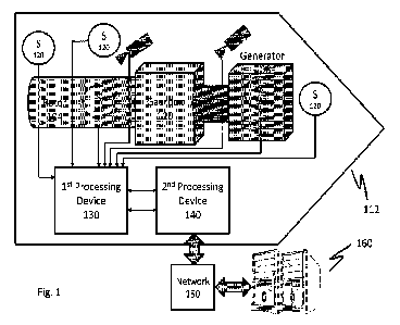
[0019] FIG. 1 is a block diagram illustrating a
system architecture in accordance with
an exemplary embodiment of the present disclosure.
[0020] As shown in Fig. 1, the system 100 for
determining an operating condition for a
10 wind turbine having a rotor 104, generator 106, a high speed coupling
shaft 108, and a
gearbox 110. The system includes a plurality of sensors 120 mounted within a
nacelle 112
of the wind turbine. The sensors 120 can include one or more non-contact
proximity
sensors, one or more video cameras, one or more thermal cameras, one or more
gas
sensors, or any other suitable sensor for measuring a parameter or condition
of a wind
15 turbine component as desired. The one or more non-contact proximity
sensors can include
high precision and lower precision sensors. The high precision non-contact
proximity
sensors can measure movement in a range of approximately 0.0029 mm. The lower
precision non-contact proximity sensors can measure movement in a range of
approximately 0.1000 mm.
20 [0021] The video cameras can be configured for surveillance and
monitoring the
physical components within the nacelle 112 of the wind turbine. Each video
camera can
include an interface for connecting to a digital or communication network via
a suitable
Internet protocol. The video cameras can have pan, tilt, and zoom controls
which can be
manipulated or adjusted remotely and can be configured to capture video images
in a
25 suitable resolution, such as, 4K, high definition, standard definition,
or any other suitable
resolution as desired.
[0022] The one or more thermal cameras are
configured to render infrared radiation as
visible light using an array of detector elements. Each thermal camera can
include a lens
system that focuses the infrared light onto the detector array. The elements
of the detector
30 array in combination with signal processing circuitry generate a
thermogram based on the
received energy.
[0023] As shown in Fig. 1, a pair of proximity
sensors of the plurality of sensors can be
mounted adjacent to the rotor 104 for measuring rotor displacement. A first
processing
device 130 connected to receive sensor data from the pair of proximity sensors
110 and
35 configured to partition the received sensor data into predefined
datasets. According to an
3
CA 03154395 2022-4-11
WO 2021/071884
PCT/US2020/054493
exemplary embodiment, the first processing device 130 can be configured as an
interface
for collecting the real-time (e.g., live-stream) data from each of the
plurality of sensors. A
second processing device 140 is connected to the first processing device 130
and is
configured to format the predefined datasets for transmission over a network
150 to a
5 processing server or computer 160. The second processing device 140 can
be configured
to receive the sensor data as the sensor data from the first processing device
130, which is
configured as an interface. According to an exemplary embodiment, the
operations of the
first and second processing devices 130, 140 can be achieved through a single
processing
or computing device. The remote computing device 160 can be configured to
receive
10 predefined datasets of sensor data from the second processing device 140
and determine
whether any of the rotor displacement, the high speed coupling displacement,
the
generator displacement, and the gearbox displacement is outside accepted
ranges. For
example, the remote computing device 160 can be configured as a processing
server
which executes any number of algorithms and/or software applications for
analyzing the
15 sensor data according to predetermined setpoints and/or ranges for
determining the
operating condition or status of the wind turbine and the various components
as desired.
The processing server 160 can be further configured to execute an application
program
interface (API) or other suitable graphic display for notifying a user or
operator of the
results of the analysis and/or determination. The API can also be configured
to display or
20 indicate the data or component under analysis and allow an operator to
select one or more
of the plurality of sensors for evaluating the wind turbine and/or associated
component.
[0024] FIG. 2 is a block diagram illustrating a
processing device in accordance with an
exemplary embodiment of the present disclosure. As shown in Fig. 2, the
computing
devices 130, 140, 160 can include an input/output (I/O) interface 200, a
hardware
25 processor 210, a communication interface 220, and a memory device 230.
[0025] The I/O interface 200 can be configured to
receive a signal from the hardware
processor 210 and generate an output suitable for a peripheral device via a
direct wired or
wireless link. The I/O interface 200 can include a combination of hardware and
software
for example, a processor, circuit card, or any other suitable hardware device
encoded with
30 program code, software, and/or firmware for communicating with a
peripheral device such
as a display device, printer, audio output device, or other suitable
electronic device or
output type as desired.
[0026] The hardware processor 210 can be a special
purpose or a general purpose
processing device encoded with program code or software for performing the
exemplary
35 functions and/or features disclosed herein. The hardware processor 210
can be connected
to a communications infrastructure 212 including a bus, message queue,
network, multi-
4
CA 03154395 2022-4-11
WO 2021/071884
PCT/US2020/054493
core message-passing scheme, for communicating with other components of the
first and
second processing devices 130, 140, such as the communications interface 220,
the I/O
interface 200, and the memory device 230. The hardware processor 210 can
include one
or more processing devices such as a microprocessor, central processing unit,
5 microcomputer, programmable logic unit or any other suitable hardware
processing
devices as desired.
[0027] The communications interface 220 can include a
combination of hardware and
software components and be configured to receive data from the plurality of
sensor devices
120. The communications interface 220 can include a hardware component such as
an
10 antenna, a network interface (e.g., an Ethernet card), a communications
port, a PCMC IA
slot and card, or any other suitable component or device as desired. The
communications
interface 220 can be encoded with software or program code for receiving
signals and/or
data packets encoded with sensor data from another device, such as a database,
image
sensor, image processor or other suitable device as desired. The communication
interface
15 220 can be connected to the plurality of sensor devices via a wired or
wireless network or
via a direct wired or wireless link. The hardware and software components of
the
communication interface 220 can be configured to receive the sensor data
according to
one or more communication protocols and data formats. For example, the
communications
interface 220 can be configured to communicate over a network 150, which may
include a
20 local area network (LAN), a wide area network (WAN), a wireless network
(e.g., VVi-Fi), a
mobile communication network, a satellite network, the Internet, fiber optic,
coaxial cable,
infrared, radio frequency (RF), Modbus, I2C, or any combination thereof
[0028] The communication interface 220 can be
configured to receive the sensor data
as a live data stream from one or more of the plurality of sensors. According
to an
25 exemplary embodiment, the sensor data can also be obtained as recorded
or stored data
from a database or memory device. During a receive operation, the receiving
unit 110 can
be configured to identify parts of the received data via a header and parse
the data signal
and/or data packet into small frames (e.g., bytes, words) or segments for
further
processing at the hardware processor 210.
30 [0029] According to an exemplary embodiment, the communications
interface 220 can
be configured to receive data from the processor 210 and assemble the data
into a data
signal and/or data packets according to the specified communication protocol
and data
format of a peripheral device or remote device to which the data is to be
sent. The
communications interface 220 can include any one or more of hardware and
software
35 components for generating and communicating the data signal over the
network 150 and/or
via a direct wired or wireless link to a peripheral or remote device.
CA 03154395 2022-4-11
WO 2021/071884
PCT/US2020/054493
[0030] As already discussed, the system can include a
plurality of sensor devices 120
that are arranged in various locations in the nacelle 112. FIG. 3 is a block
diagram
illustrating a sensor arrangement associated with a rotor in accordance with
an exemplary
embodiment of the present disclosure. As shown in Fig. 3, the sensors can be
non-contact
5 proximity sensors that monitor rotor displacement in two directions. For
example, one
sensor in the pair of non-contact proximity sensors can be positioned to
monitor a balance
property of the rotor 104 from a top position, and the other sensor in the
pair can be
positioned at a side position relative to the rotor 104.
[0031] FIG. 4 is a block diagram illustrating a
sensor arrangement associated with a
10 generator in accordance with an exemplary embodiment of the present
disclosure. As
shown in Fig. 4, the plurality of sensors includes a pair of non-contact
proximity sensors
mounted adjacent to the generator 106 for measuring generator displacement.
For
example, one sensor in the pair of non-contact proximity sensors can be
disposed in a front
position relative to the generator 106 and the other sensor can be positioned
at a side
15 position relative to the generator 106. The non-contact proximity
sensors of Fig. 4 can be
disposed to monitor or detect forward, backward, and side movement of a foot
410 of the
generator 106.
[0032] FIG. 5 is a block diagram illustrating a
sensor arrangement associated with a
high speed coupling shaft in accordance with an exemplary embodiment of the
present
20 disclosure. As shown in Fig. 5, the sensor arrangement includes a pair
of non-contact
proximity sensors arranged proximal to the high speed coupling shaft 108 of
the rotor 104
and generator 106. The pair of non-contact proximity sensors includes one
sensor
arranged in a top position relative to the high speed coupling shaft 110 and a
side position.
[0033] FIG. 6 is a block diagram illustrating a
sensor arrangement associated with a
25 gearbox in accordance with an exemplary embodiment of the present
disclosure. As
shown in Fig. 6, the plurality of sensors includes a pair of non-contact
proximity sensors
mounted adjacent to the gearbox 110 for measuring gearbox displacement. The
pair of
non-contact proximity sensors positioned to monitor forward, backward, up, and
down
movement of the gearbox 110. According to an exemplary embodiment of the
present
30 disclosure, one sensor in the pair can be positioned in proximity to a
torque arm of the
gearbox 110 to measure up and down movement. Another one of the pair of
sensors can
be focused on the body of the gearbox 110 to measure forward and backward
movement.
[0034] As already discussed the plurality of sensors
can include video cameras to
provide visual monitoring and surveillance within the nacelle 112 for
observing movement
35 and/or vibration in various components of the wind turbine.
6
CA 03154395 2022-4-11
WO 2021/071884
PCT/US2020/054493
[0035] FIG. 7 is a block diagram illustrating a
camera arrangement associated with a
gearbox in accordance with an exemplary embodiment of the present disclosure.
As
shown in Fig. 7, the camera is positioned to look at a front side of the
gearbox 110 during
operation.
5 [0036] FIG. 8 is a block diagram illustrating a camera arrangement
associated with a
high speed coupling shaft in accordance with an exemplary embodiment of the
present
disclosure. As shown in Fig. 8, one or more sensors can be mounted adjacent to
couplings
connecting the gearbox 110 and the generator 106. The sensor can include a
camera
disposed to have a side vantage point of the high speed coupling shaft 108 for
measuring
10 displacement. This camera provides video data and a vantage point of the
gearbox 110
which allows movement and/or vibration to be visually observed. The video
cameras of
Figs. 7 and 8 can be configured to receive power over an Ethernet connection
and
communicate data over the Ethernet connection to the first processing device
using a
secure IP protocol.
15 [0037] FIG. 9 is a block diagram illustrating a thermal sensor
arrangement associated
with a main shaft assembly in accordance with an exemplary embodiment of the
present
disclosure. As shown in Fig. 9, the senor arrangement includes a thermal
sensor 900 that
is positioned to detect thermal radiation from the main shaft assembly 910.
The main shaft
assembly 910 includes a main bearing 912, a main shaft 914, and a gearbox 916.
20 [0038] Fig. 10 is a flow diagram of a method for determining an
operating condition of a
wind turbine in accordance with an exemplary embodiment of the present
disclosure. In
step 1000, the first processing device receives data from one or more of the
plurality of
sensors mounted within the nacelle 112 of the wind turbine. The received data
is
associated with one or more of rotor displacement, gearbox displacement,
coupling
25 displacement for a high speed coupling shaft 108 between the gearbox 110
and the
generator 106, generator displacement, and a temperature of the main shaft
assembly via
a thermal image. The first processing device 130 partitions the received
sensor data into
predefined datasets (step 1010) and formats the predefined datasets for
transmission over
a network (step 1020). For example, the first processing device 130 can
receive raw
30 sensor data including measurement data and generate a header, which
identities the
sensor from which the data originated. The first processing device 130 can
assemble the
header and measurement data according to a specified data format or protocol.
According
to an exemplary embodiment, the header and measurement data can be formatted
into a
comma delimited string with a termination character. For example, if the
received sensor
35 data originated from a sensor reading measurements associated with the
high speed
coupling shaft 108, the data can be formatted as follows:
7
CA 03154395 2022-4-11
WO 2021/071884
PCT/US2020/054493
"HIGHSPEED,100,120,110,120,150,92,133,!"
[0039] The header "HIGHSPEED" indicates the
measurement data is from the high
speed coupling shaft 108. The header is followed by the measurement data in
which
measurements for specified time readings are delimited by commas. The
character 1",
5 which follows the measurement data, is a terminating character indicating
the end of the
dataset. It should be understood that the dataset can include one or more
additional data
elements according to the specified protocol for communication and/or
analysis.
[0040] The first processing device 130 sends the
formatted datasets to the second
processing device 140 for analysis. The second processing device 140 processes
the
10 datasets to determine whether the rotor displacement is within an
accepted range.
According to an exemplary embodiment, the second processing device 140 can
execute
any of a number of algorithms to analyze the received datasets and determine
whether the
measurement data indicates that any of the rotor 104, gearbox 110, generator
106, and/or
high speed coupling shaft 108 is or has experienced displacement which is
outside of
15 accepted tolerances.
[0041] According to another exemplary embodiment,
when the received sensor data
includes video data, the second processing device 140 can be configured to
execute image
recognition and/or image analysis software for determining an operating
condition of the
monitored component in the image. For example, via image analysis, the second
20 processing device 140 can be configured to determine a significance of
any vibrations
and/or movement in the monitored component. Moreover, the image analysis can
recognize any defects or deterioration in the monitored component, such as
cracks,
deformities, leaks, or any other suitable deficiency in the monitored
component as desired.
[0042] According to yet another exemplary embodiment,
when the received sensor
25 data includes audio data, the second processing device 140 can be
configured to execute
audio recognition and/or audio analysis software for determining an operating
condition of
the monitored component. For example, the second processing device 140 can be
configured to analyze the sound patterns and determine whether any of the
patterns
indicate an adverse, defective, or deteriorating operating condition with
respect to the
30 monitored component when compared to baseline sound patterns.
[0043] According to an exemplary embodiment of the
present disclosure, when the
received sensor data includes thermal imaging data, the second processing
device 140
can be configured to execute thermal analysis software for determining whether
the
thermal profile of the monitored component is outside of an accepted range or
tolerance_
35 Furthermore, the second processing device 140 can be configured to
generate a graphic
8
CA 03154395 2022-4-11
WO 2021/071884
PCT/US2020/054493
display and/or graphic representation of the thermal profile of the monitored
component.
According to an exemplary embodiment, the graphic display can identify
specified areas or
portions of the monitored component which are within and/or outside of the
accepted
temperature range and/or those areas that may be under increased stress.
5 [0044] The computer program code for performing the specialized
functions described
herein can be stored on a medium and computer usable medium, which may refer
to
memories, such as the memory devices for the first and second computing device
130, 140
and the remote computing device 160, which may be memory semiconductors (e.g.,
DRAMs, etc.). These computer program products may be a tangible non-transitory
means
10 for providing software to the computing devices 130, 140, and 160
disclosed herein. The
computer programs (e.g., computer control logic) or software may be stored in
a resident
memory device 230 and/or may also be received via the communications interface
220.
Such computer programs, when executed, may enable the associated computing
devices
and/or server to implement the present methods and exemplary embodiments
discussed
15 herein and may represent controllers of the computing device 130, 140,
160. Where the
present disclosure is implemented using software, the software may be stored
in a
computer program product or non-transitory computer readable medium and loaded
into
the corresponding device 130, 140, 160 using a removable storage drive, an 110
interface
200, a hard disk drive, or communications interface 220, where applicable.
20 [0045] The hardware processor 210 of the computing device 100 can
include one or
more modules or engines configured to perform the functions of the exemplary
embodiments described herein. Each of the modules or engines may be
implemented
using hardware and, in some instances, may also utilize software, such as
corresponding
to program code and/or programs stored in memory 230. In such instances,
program code
25 may be compiled by the respective processors (e.g., by a compiling
module or engine)
prior to execution. For example, the program code may be source code written
in a
programming language that is translated into a lower level language, such as
assembly
language or machine code, for execution by the one or more processors and/or
any
additional hardware components. The process of compiling may include the use
of lexical
30 analysis, preprocessing, parsing, semantic analysis, syntax-directed
translation, code
generation, code optimization, and any other techniques that may be suitable
for
translation of program code into a lower level language suitable for
controlling the
computing device 130, 140, 160 to perform the functions disclosed herein.
According to an
exemplary embodiment, the program code can be configured to execute a neural
network
35 architecture, or machine teaming algorithm wherein the image, sound,
and/or thermal
analysis operations can be performed according to corresponding training
vectors and the
9
CA 03154395 2022-4-11
WO 2021/071884
PCT/US2020/054493
neural network can learn further patterns and/or features identifying an
operating condition
or event from each subsequent analysis. It will be apparent to persons having
skill in the
relevant art that such processes result in the computing device 130, 140, 160
being a
specially configured computing devices uniquely programmed to perform the
functions
5 discussed above.
[0046] While various exemplary embodiments of the
disclosed system and method
have been described above it should be understood that they have been
presented for
purposes of example only, not limitations. It is not exhaustive and does not
limit the
disclosure to the precise form disclosed. Modifications and variations are
possible in light
10 of the above teachings or may be acquired from practicing of the
disclosure, without
departing from the breadth or scope.
CA 03154395 2022-4-11