Note : Les descriptions sont présentées dans la langue officielle dans laquelle elles ont été soumises.
- 1 -
METHOD AND TRENCH CUTTING DEVICE FOR PRODUCING A CUT TRENCH IN
THE GROUND
The invention relates to a method for producing a cut trench in the ground by
means
of a trench cutting device having a trench cutter and a supporting means which
is
designed for lifting and lowering the trench cutter, wherein the trench cutter
is
connected at its upper end to the supporting means and at its lower end has at
least
one cutting wheel which is rotatably supported and can be driven in a rotating
manner
via a rotary drive in order to remove ground material, wherein a target value
for an
advancing speed of the trench cutter during removal of ground material can be
preset
in a control unit, through which a lowering of the trench cutter by the
supporting means
into the ground is controlled, in accordance with the preamble of claim 1.
The invention further relates to a trench cutting device having a trench
cutter and a
supporting means which is designed for lifting and lowering the trench cutter
into the
ground, wherein the trench cutter is connected at its upper end to a
supporting means
and at its lower end has at least one cutting wheel which is rotatably
supported and
driven in a rotating manner via a rotary drive in order to remove ground
material,
wherein a control unit is furthermore provided, through which a lowering of
the trench
cutter by the supporting means into the ground can be controlled, wherein a
target
value for an advancing speed of the trench cutter during removal of ground
material
can be entered into the control unit, in accordance with the preamble of claim
10.
A generic method can be taken from EP 0 790 356 Bl. In this known trench
cutting
device a trench cutter is lowered with a target advancing speed into the
ground. The
target advancing speed is entered into a control means. In this process, a
load of the
trench cutter is detected by the control means. If a load of the trench cutter
and
therefore a specific pressing force onto the cutting wheels is exceeded, the
advancing
speed of the trench cutter is reduced. This serves to avoid overloading of the
cutting
wheels in cutting operation.
CA 03154436 2022-4-11
- 2 -
The detection of a load on a trench cutter during cutting is relatively
laborious and is
also accompanied by inaccuracy. Due to the relatively high weight of a trench
cutter it
is necessary that during lowering into the ground and during removal of ground
material
the trench cutter is to be constantly subjected to a certain pull force, with
which the
cutting wheels are relieved of a part of the applied weight force of the
trench cutter.
To determine the load it is therefore common practice to detect a force on the
cutter
winch or a supporting rope of the trench cutter. However, on this force value
further
factors, such as the friction of the cutter on the trench walls and the type
of filling of the
trench with a stabilizing liquid, have a not insignificant influence. To avoid
overloading
of the cutting wheels that can lead to increased wear or destruction of the
cutting teeth
a corresponding safety factor has to be taken into account in the measured
load value.
This makes it more difficult to operate the trench cutting device at an upper
power limit,
at which a high cutting progress concurrent with low wear is ensured.
The invention is based on the object to provide a method and a trench cutting
device for producing a cut trench in the ground, with which a trench cutting
device can
be operated in a particularly efficient manner.
The object is achieved on the one hand by a method having the features of
claim 1
and on the other hand by a trench cutting device having the features of claim
10.
Preferred embodiments are stated in the respective dependent claims.
The method according to the invention is characterized in that the advancing
speed is
controlled by means of the control unit depending on a rotational speed and/or
a torque
of the at least one cutting wheel, wherein on reaching a preset limit value
for the
rotational speed and/or for the torque the advancing speed of the trench
cutter is
changed, in particular reduced, with respect to the target value for the
advancing
speed.
The invention is based on the finding that for the control or regulation of
the advancing
speed the rotational movement of the at least one cutting wheel can be used.
The
rotational movement of the cutting wheel can in particular be considered as
the
rotational speed and/or the torque of the cutting wheel. If the advancing
speed is too
high for an in-situ ground layer, the rotational speed of the cutting wheel
decreases
and a torque present at the cutting wheel increases. If the rotational speed
drops,
CA 03154436 2022-4-11
- 3 -
favorable cutting conditions for a high removal rate no longer prevail. In
addition, with
an increase of the torque a load of the cutting wheel transmission and of the
removal
teeth rises and there is the risk of tooth breakage. Therefore, the rotational
movement
allows a very good conclusion as to whether a preselected target advancing
speed is
too high or, as the case may be, even too low for an in-situ ground layer. In
addition to
a reduction of the advancing speed an increase can be provided too. Within the
meaning of the invention a limit value can be understood not only as a
specific single
value but also as a limit range with a value range.
The invention is furthermore based on the finding that a rotational movement
and in
particular a rotational speed and/or a torque of the at least one cutting
wheel can be
detected relatively easily and precisely as compared to a load. This permits a
very
precise and also quick control or regulation of a trench cutter during removal
of ground
material. Thus, the invention makes it possible for even an inexperienced
device
operator to work close to the power limit of a trench cutter so that an
efficient cutting
with a high daily rate can be achieved.
Within the meaning of the invention a limit value does not have to be a fixed
value.
This can also be a dynamic limit value that depends on other factors and/or
parameters, e.g. on ground parameters etc., and can change. The limit values
can in
particular be limit value characteristics that are stored in the control as
characteristic
curies or tables.
A preferred embodiment of the invention resides in the fact that on reaching
the limit
value for the rotational speed or the torque the advancing speed of the trench
cutter is
reduced until the rotational speed is again above a preset rotational speed
limit value
or the torque is below a preset torque limit value. The trench cutter can thus
be
operated with a relatively high target advancing speed and with a relatively
high load.
If the rotational speed falls below a preset limit value or if the torque
rises above a
preset limit value, the control unit is designed such that the advancing speed
is
changed, in particular reduced until the rotational speed is again above a
preset
rotational speed limit value or the torque is below a preset torque limit
value. A
reduction of the advancing speed usually also brings about a reduction of the
load on
the trench cutter. In this way, the at least one cutting wheel can be
relieved, thus
resulting in an increase in rotational speed or a reduced torque requirement.
CA 03154436 2022-4-11
- 4 -
It is especially preferred that the advancing speed of the trench cutter is
increased up
to the target value for the advancing speed if the rotational speed is above
the
rotational speed limit value or the torque is below the torque limit value, In
this way, a
regulation of the advancing speed can be effected as a function of the
measured
rotational speed or the measured torque. The limit value, on reaching of which
the
advancing speed is reduced, can be equal to the rotational speed limit value
or the
torque limit value, at which the advancing speed is increased again. By
preference,
however, these limit values can also be different and constitute a limit
range. This
counteracts the risk of the regulation of the system giving rise to
oscillations.
Moreover, for an efficient cutting operation it can be expedient that the
advancing
speed is furthermore controlled depending on a load of the trench cutter. The
load can
be detected as an additional measured value, in which case a limit value for
an upper
load and a lower load, at which the advancing speed is reduced or increased,
can also
be entered into the control unit.
According to a further development of the invention particularly good control
or
regulation of the trench cutter is achieved in that the rotational speed or
the torque is
detected in a direct manner and a related measured value is forwarded to the
control
unit.
In conjunction with this, it is particularly preferred that the rotational
speed is detected
by means of a rotational speed pickup or the torque is detected by means of a
torque
pickup. Rotational speed pickups are sufficiently known and can detect a
rotational
speed e.g, on a drive shaft in particular in a contactless manner. Detection
can take
place optically, inductively, magnetically or in another known way.
Correspondingly,
known torque pickups can be provided on a drive shaft of the cutting wheel for
example. Known torque pickups can operate e.g. electronically with one or
several
strain gauges positioned on a shaft.
Alternatively or additionally, according to a further development of the
method pursuant
to the invention provision can be made for the rotational speed and/or the
torque to be
detected in an indirect manner. As a result, in particular measuring means
located
directly on the cutting wheel or the cutting wheel transmission can be
avoided.
CA 03154436 2022-4-11
- 5 -
It is particularly preferred that in order to detect the rotational speed
and/or the torque
a power consumption of the rotary drive is measured. For example if, at a
preset
advancing speed, the cutting wheel makes contact with a ground layer of
greater
compactness this can be detected due to an increase in the power consumption
of the
rotary drive. This is generally possible with all drive types, for example
also with an
electric rotary drive.
A preferred embodiment variant of the invention resides in the fact that the
rotary drive
is operated hydraulically with a hydraulic circuit, wherein a pressure or a
pressure
change is detected in the hydraulic circuit. In trench cutters with hydraulic
drive the
pressure present at hydraulic pumps of the hydraulic circuit can be used to
control or
regulate the advancing speed. For example if the torque rises above a defined
limit
value and therefore the pressure present at the hydraulic pumps, the advancing
speed
can be reduced. Here, a limit value can preferably lie approximately 10 %
below the
pressure for a maximum rotational speed or a maximum torque in order to retain
sufficient reserve during operation of the cutting wheels.
Moreover, the control unit can be designed such that in the case of complete
blockage
of the at least one cutting wheel the trench cutter is slightly raised through
the control
unit by means of the supporting means. This reduces the contact force and
therefore
the required torque. The cutting wheels can thus start to rotate again.
With regard to the trench cutting device the invention is characterized in
that the control
unit is designed for controlling the advancing speed depending on a rotational
speed
and/or a torque of the at least one cutting wheel and for presetting a limit
value for the
rotational speed and/or the torque, wherein on reaching the preset limit value
for the
rotational speed or for the torque the advancing speed of the trench cutter
can be
reduced with respect to the target value for the advancing speed. Within the
meaning
of the invention the term control is to be understood in a broad sense and can
also
comprise a regulation.
With the trench cutter according to the invention the previously described
method can
be carried out in particular. The advantages described beforehand can be
achieved
thereby.
CA 03154436 2022-4-11
- 6 -
A preferred embodiment of the trench cutting device according to the invention
can be
seen in the fact that the supporting means is a carrier implement with a
supporting rope
or a supporting rod, wherein the trench cutter is suspended in a vertically
adjustable
manner on the supporting rope or the supporting rod. The supporting rope or
the
supporting rod forms a supporting element, with which the trench cutter can be
sunk
vertically into the ground. For this purpose, the supporting means can have a
winch for
the supporting rope or a linear drive, more particularly a hydraulic cylinder
means, for
the supporting rod. A load can in this case be detected by a force pickup on
the winch
or a pressure sensor in the hydraulic system of the hydraulic cylinder.
Basically, the trench cutting device can be designed with only one cutting
wheel or with
a pair of two cutting wheels. A purposeful operation of the trench cutting
device is
achieved by the fact that a total of four cutting wheels are provided which
are arranged
in pairs next to each other. The axis of the at least one cutting wheel is
directed
transversely to the direction of advance, in particular being directed
horizontally. In the
case of two cutting wheel pairs each the two cutting wheels of a cutting wheel
pair
rotate about the same cutting wheel axis, The cutting wheel axes of the two
cutting
wheel pairs are arranged in parallel and spaced apart from each other.
The invention is described in greater detail hereinafter by way of a preferred
embodiment illustrated schematically in the accompanying Figure. The single
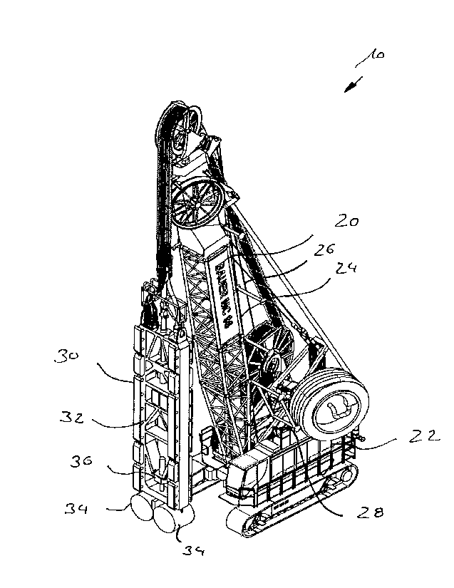
accompanying Figure shows a perspective view of a trench cutting device 10
according
to the invention.
The trench cutting device 10 according to the Figure has a supporting means 20
with
a carrier implement 22 that is provided with a crawler-track running gear. On
the carrier
implement 22 a mast 24 is supported in an approximately vertically directed
manner,
over the mast head of which a supporting rope 26 is guided.
At the free end of the supporting rope 26 a generally known trench cutter 30
with a
scaffold-like cutter frame 32 is suspended. The supporting rope 26 is
connected to the
trench cutter 30 at an upper end thereof, The other end of the supporting rope
26 is
guided to a winch 28, indicated only, on the carrier implement 22. By means of
the
winch 28 the trench cutter 30 can be lifted and lowered vertically.
CA 03154436 2022-4-11
- 7 -
At a lower end of the cutter frame 32 of the trench cutter 30 a total of four
cutting wheels
34 are each arranged in pairs, as illustrated schematically only in the
Figure. By way
of a rotary drive 36 on the cutter frame 32, which is indicated schematically
in the
Figure and driven hydraulically, the cutting wheels 34 can be set into
rotating motion.
When lowering the trench cutter 30 into the ground, ground material can be
removed
by the rotating cutting wheels 34.
An advancing speed of the trench cutter 30 can, for example, be determined on
the
winch 28 by measuring the winch rotation over time. In a control unit on the
carrier
implement 22 a target value for the advancing speed can be entered, whereby
e.g. the
winch 28 is actuated accordingly.
Furthermore, by the control unit a rotational speed and/or a torque of the
cutting wheels
34 can be detected directly or indirectly through the pressure prevailing at
the hydraulic
units that are also arranged on the carrier implement 22. If, at a preset
advancing
speed of the trench cutter 30, the rotational speed at the cutting wheels 34
falls below
a preset limit value, a drive of the winch 28 can be actuated by the control
unit in order
to reduce the advancing speed of the trench cutter 30. This reduction of the
advancing
speed of the trench cutter 30 takes place until the rotational speed of the
cutting wheels
34 is again above a rotational speed limit value. Afterwards, through
corresponding
actuation of the winch 28, the advancing speed of the trench cutter 30 can be
increased
again by the control unit until the preset advancing speed of the trench
cutter 30 is
reached. Alternatively or additionally, a control or regulation can also take
place by
taking into account the torque on the cutting wheels 34.
CA 03154436 2022-4-11