Note : Les descriptions sont présentées dans la langue officielle dans laquelle elles ont été soumises.
WO 2021/078899 1
PCT/EP2020/079820
Generation of electrical power offshore
This invention relates to the generation of electrical power at offshore
locations. The
invention is particularly concerned with the challenges of stabilising power-
generation
5 facilities moored in deep water, such as the multiple windmills or wind
turbines of a
floating windfarm. The invention is also concerned with the challenges of
transferring
power among offshore power-generation facilities and for exporting power from
such
facilities, typically to an onshore power grid.
10 To date, floating wind turbines have typically been configured in
parallel straight-line
arrays. The turbines of such arrays are typically connected electrically in
series by
dynamic umbilicals and are also connected electrically to a floating
substation
structure.
15 Conventionally, floating wind turbines are anchored offshore via mooring
lines that are
connected to respective anchors placed on, or embedded into, the seabed. Such
an
arrangement is practical where the water is relatively shallow, for example
with a depth
of up to around 150m. However, it is difficult to achieve sufficient stability
with
conventional mooring arrangements in significantly deeper water. Consequently,
20 excessive movement of turbines relative to the seabed, and relative to
each other, can
generate unacceptable fatigue in the umbilicals or cables that are used to
transfer
power within a windfarm or to export power from the windfarm.
Another problem is that where multiple floating wind turbines are grouped in
an
25 offshore windfarm, the water column becomes congested with mooring
lines. This
presents a risk of clashing with or between mooring lines, especially as the
horizontal
spread of the moorings tends to increase with water depth.
WO 02/10589 discloses an anchoring pattern for multiple wind turbines, in
which at
30 least some mooring or stabilising lines of each turbine share subsea
foundations with
mooring or stabilising lines of other turbines. The arrangement disclosed
relies on a
primary taut vertical cable and auxiliary catenary cables serving as legs.
However, the
use of a vertical cable in deep water is impractical and presents an
unacceptable risk of
failure.
In JP 3944445, the wind turbines of an array are connected together by
stabilising
connecting lines. Intermediate weights on the connecting lines confer a degree
of
CA 03155011 2022-4-14
WO 2021/078899 2
PCT/EP2020/079820
stability that may be sufficient for use in shallow water but are not
sufficient for use in
deep water. A larger stabilising system would be needed in that case.
In view of these problems, the inventors have identified a need for improved
layouts
5 and mooring arrangements for offshore power-generation facilities,
notably for
windfarms that comprise multiple floating wind turbines. The advent of deep-
water
installation of wind turbines and the desirability of connection with subsea
energy
storage systems presents new challenges, especially in remote locations.
10 The prior art includes numerous mooring proposals for floating oil and
gas production
facilities. However, that prior art does not teach a solution to the problems
addressed
by the present invention. For example, VVO 97/48596 discloses a mooring line
pattern
for a floating production vessel, in which catenary mooring lines double as
flowlines for
hydrocarbon production fluids.
Other prior art from the subsea oil and gas industry is too complex or
otherwise wholly
unsuitable for the purposes of the invention. For example, WO 2008/152505
teaches
combining mooring lines and production risers through a disconnectable buoy
between
the seabed and the surface. In US 6408781, a platform is anchored in deep
water
20 using a combination of deep-water mooring lines supported by
intermediate buoys and
shallow-water moorings connected to the buoys. WO 97/29943 discloses an even
more
complex mooring pattern in which various mooring lines are connected together.
Against this background, the invention provides a floating power-generation
group that
25 comprises: a floating hub such as a spar buoy or a buoyant platform that
is anchored to
subsea foundations by a plurality of anchor lines; and at least two floating
power
producer units that are connected electrically and mechanically to the hub.
The power
producer units are each moored by a plurality of mooring lines, at least one
of those
mooring lines extending inwardly toward the hub to effect mechanical
connection to the
30 hub and at least one other of those mooring lines extending outwardly
toward one of
the subsea foundations.
The anchor lines and/or the mooring lines may, for example, be catenaries or
taut legs
that are held in tension by buoyant upthrust of the hub and/or the power
producer units.
The outwardly-extending mooring lines may each be joined at a lower end to a
lower
chain section of a respective anchor line, or directly to a respective subsea
foundation.
CA 03155011 2022-4-14
WO 2021/078899 3
PCT/EP2020/079820
In either case, each of the outwardly-extending mooring lines may conveniently
share
one of the subsea foundations with one of the anchor lines.
Similarly, the inwardly-extending mooring lines may each be joined at an upper
end to
5 an upper section of a respective anchor line, or directly to the hub.
Each power producer unit is suitably moored between an adjacent pair of the
anchor
lines radiating from the hub. In top plan view, the power producer units are
preferably
closer to the hub than the subsea foundations.
Each of the mooring lines extending from the power producer units may converge
with
or intersect one of the anchor lines. For example, the mooring lines may
intersect the
anchor lines at junctions between a major central wire or rope section of the
anchor line
and a minor upper or lower section of the anchor line. The upper and/or lower
sections
15 of the anchor line may, for example, be of chain.
The power producer units may be substantially equidistant from the hub, for
example
being distributed around a substantially circular array that is centred on the
hub. In any
event, the power producer units and the anchor lines may alternate
circumferentially
20 around the hub.
Conveniently, the hub may house switchgear in a dry environment. The hub may
similarly house a step-up transformer that is connected to a power export link
Similarly, dry splice connections may be made between power umbilicals and the
25 power producer units and the hub. Such umbilicals thereby effect
electrical connections
between the power producer units and the hub and may hang as catenaries
between
the power producer units and the hub.
The invention also provides a floating power-generation group that comprises:
a
30 floating hub and at least two floating power producer units that are
connected
electrically to the hub; wherein the floating hub is anchored to subsea
foundations that
are located between the power producer units and the hub; wherein the power
producer units are each moored by a plurality of mooring lines, at least one
of those
mooring lines extending inwardly toward one of the subsea foundations located
35 between the power producer unit and the hub, and at least one other of
those mooring
lines extending outwardly toward a further subsea foundation outboard of the
power
producer unit.
CA 03155011 2022-4-14
WO 2021/078899 4
PCT/EP2020/079820
Each power producer unit may additionally be moored by a further mooring line
that
extends inwardly toward the hub to effect mechanical connection to the hub.
5 The power-generation group may generally include any of the features
described
above in connection with the first aspect of the present invention.
The inventive concept also embraces a set comprising a plurality of the power-
generation groups of the invention, the hub of each of those groups being
connected
10 electrically to the hub of at least one other of those groups.
The power-generation groups of the set may be arranged in at least two rows.
Alternatively, the power-generation groups of the set may include a central
power-
generation group and an array of power-generation groups that at least
partially
15 surround the central power-generation group, for example in a looped or
circular array.
Elegantly, anchor lines extending from hubs of different groups of the set may
be
anchored to common subsea foundations.
20 The hub of at least one group of the set may be configured to serve as
an electrical
substation for the hub of at least one other group of the set.
Advantageously, the set may further comprise at least one subsea energy
storage unit
that is electrically connected to at least one of the hubs. Such an energy
storage unit
25 may, for example, comprise a storage volume in fluid communication with
pumping
machinery that is arranged to expel water from the storage volume and with
generating
machinery that is arranged to generate electricity from a flow of water
entering the
storage volume. The pumping machinery may be positioned at a greater water
depth
than the generating machinery.
The storage volume of the energy storage unit may be elongate, extending
between
groups of the set. Terminal structures at each end of the storage volume may
conveniently house the pumping and generating machinery_ In particular, the
pumping
machinery may be housed in a terminal structure at one end of the storage
volume and
35 the generating machinery may be housed in a terminal structure at an
opposite end of
the storage volume. In top plan view, each terminal structure is preferably
located
closer to a hub than the power producer units of a group comprising that hub.
The
CA 03155011 2022-4-14
WO 2021/078899 5
PCT/EP2020/079820
energy storage unit suitably comprises at least one cable that effects
electrical
connection between the hubs of different groups of the set.
Wet-mate connections may be made between the pumping machinery, the generating
5 machinery and umbilicals suspended from the hubs.
The hub of at least one group of the set may be configured to switch power
generated
by the power producer units of that group to drive the pumping machinery of
the energy
storage unit Conversely, the hub of at least one group of the set may be
configured to
10 combine power generated by the power producer units of that group with
power
generated by the generating machinery of the energy storage unit.
The inventive concept also provides a set of floating power-generation groups
each
comprising a floating hub and a plurality of floating power producer units
that are
15 connected electrically to the hub.
The hub of at least one of the power-generation groups may be connected
electrically
to and configured to serve as an electrical substation for the hub of at least
one other of
the power-generation groups.
The power-generation groups of the set may be arranged in at least two rows
including
a first row and a second row. In this case the hub of at least one of the
power-
generation groups in the first row may be connected electrically to and
configured to
serve as an electrical substation for the hub of at least one of the power-
generation
25 groups in the second row.
Alternatively, the power-generation groups of the set may include a central
power-
generation group and an array of power-generation groups that at least
partially
surround the central power-generation group. In this case the hub of the
central power-
30 generation group may be connected electrically to and configured to
serve as an
electrical substation for the hub of at least one of the surrounding power-
generation
groups.
The hubs and/or power producer units of the power-generation groups may be
35 connected to subsea foundations on the seabed. At least one of the power-
generation
groups may share at least one subsea foundation with at least one other of the
power-
generation groups.
CA 03155011 2022-4-14
WO 2021/078899 6
PCT/EP2020/079820
Where the power-generation groups of the set are arranged in at least two
rows, each
of the power-generation groups may share at least one subsea foundation with
at least
one other power-generation group in its own row and at least one subsea
foundation
5 with at least one other power-generation group in another row_
Alternatively, where the power-generation groups of the set include an array
of power-
generation groups that at least partially surround a central power-generation
group, the
central power-generation group may share at least one subsea foundation with
at least
10 one of the surrounding power-generation groups, and preferably with each
of the
surrounding power-generation groups. The surrounding power-generation groups
may
each also share at least one subsea foundation with at least one other of the
surrounding power-generation groups.
15 The inventive concept also extends to an offshore power-generation
arrangement,
comprising: a plurality of power-generation groups, each group comprising a
hub that is
connected electrically to a plurality of power producer units; and at least
one subsea
energy storage unit that electrically connects the hub of one of the groups to
the hub of
another of the groups.
Correspondingly, the inventive concept may be expressed as a method of
generating
electrical power offshore, which method comprises: generating electrical power
using a
plurality of power-generation groups, each group comprising a hub that is
connected
electrically to a plurality of power producer units; and conveying electrical
power from
25 the hub of one group to the hub of another group via at least one subsea
energy
storage unit. For example, electrical power may be converted to potential
energy by
pumping water from a storage volume of the subsea energy storage unit.
Thereafter,
the stored potential energy may be converted to recovered electrical power by
admitting a flow of water back into the storage volume. Water may conveniently
be
30 pumped out of the storage volume at a greater depth than the depth at
which water is
admitted into the storage volume.
Embodiments of the invention provide a floating windfarm, comprising: a
central
buoyant hub anchored to the seabed by a plurality of mooring lines; and at
least two
35 floating wind turbines electrically connected to the central hub, and
mechanically
connected to the central hub by at least one radial mooring line; wherein the
floating
wind turbines are also anchored to the seabed by mooring lines, at least one
of the
CA 03155011 2022-4-14
WO 2021/078899 7
PCT/EP2020/079820
wind turbine mooring lines being connected to a bottom section of a mooring
line of the
central hub. The mooring lines may, for example, comprise a combination of
chains
and/or spiral strand wire and/or synthetic wire.
5 The central hub may be a spar buoy or a platform, which may be anchored
by catenary
mooring legs or by taut tendons. For example, WO 2006/42178 shows a spar buoy
and
WO 97/45318 shows a tensioned leg platform.
The floating wind turbines may be at the same distance as each other from the
central
10 hub, for example distributed around the circumference of a circle
centred on the hub.
The or each radial mooring line may be a catenary line between the wind
turbine and
the central hub or the upper third of a mooring line of the central hub.
15 The central hub is apt to carry a power substation or may export power
to a subsea
substation.
Thus, the inventive concept may be exemplified by arranging wind turbines in a
circular
configuration around a central tower or spar structure that serves as an
interface with
20 subsea infrastructure.
The invention is apt to accommodate very large-diameter offshore wind turbines
as
they become available. By employing proven spar or tower solutions, the
invention can
accommodate water depths of up to 3000m. The invention also enables deep-water
25 storage of electrical energy generated offshore, noting that high-
voltage dynamic
umbilicals are not practical with existing technology.
In summary, the invention provides a floating power-generation group that
comprises a
floating hub, such as a spar buoy, which is anchored to subsea foundations by
anchor
30 lines. Floating power producer units such as wind turbines are connected
electrically
and mechanically to the hub. The power producer units are each moored by
mooring
lines. At least one mooring line extends inwardly toward the hub to effect
mechanical
connection to the hub and at least one other mooring line extends outwardly
toward a
subsea foundation.
The groups may be combined as a set whose hubs are connected electrically to
each
other, for example via subsea energy storage units. Anchor lines of different
groups
CA 03155011 2022-4-14
WO 2021/078899 8
PCT/EP2020/079820
can share subsea foundations. The storage units suitably comprise pumping
machinery
to expel water from an elongate storage volume such as a pipeline and
generating
machinery to generate electricity from a flow of water entering the storage
volume. The
pumping machinery may be in deeper water than the generating machinery.
In order that the invention may be more readily understood, reference will now
be
made, by way of example, to the accompanying drawings in which:
Figure 1 is a perspective view of a floating wind turbine unit for use in the
invention;
Figure 2 is a perspective view of a spar buoy for use in the invention;
Figure 3 is a plan view of a generating group comprising a circular array of
wind
turbine units of Figure 1 surrounding a central hub exemplified by the spar
buoy
of Figure 2;
Figure 4 is an enlarged schematic detail plan view showing alternative
mechanical connections between the spar buoy and the wind turbine units;
Figure 5 is a schematic plan view of a set of the generating groups shown in
Figure 3, each comprising an array of wind turbine units centred on a
respective
spar buoy serving as a central hub;
Figure 6 is a schematic side elevation view showing mechanical connections
between the spar buoy and one of the wind turbines of the generating group
shown in Figure 3, and also showing electrical connections to a subsea energy
storage bundle;
Figure 7 corresponds to Figure 5 but additionally shows energy storage bundles
interconnecting the hubs of the set of generating groups;
Figure 8 is a schematic plan view of set of generating groups shown in Figure
7
connected to an onshore power grid;
CA 03155011 2022-4-14
WO 2021/078899 9
PCT/EP2020/079820
Figure 9 is an electrical block diagram showing the relationships between the
arrays of wind turbine units, associated spar buoys and energy storage bundles
of the set of generating groups shown in Figures 7 and 8;
5 Figure 10 is an electrical system diagram showing electrical
connections
between the wind turbine units of one of the generating groups shown in Figure
5, the associated spar buoy and the associated energy storage bundles;
Figure 11 is an electrical system diagram showing electrical connections
10 between the wind turbine units of another of the generating
groups shown in
Figure 5, the associated spar buoy and the associated energy storage bundles,
that spar buoy serving as a substation for other generating groups;
Figures 12 to 14 are schematic perspective views showing variants of
15 mechanical and electrical connections between a wind turbine unit
and a central
hub; and
Figures 15 and 16 are schematic plan views of a set of generating groups
arranged in an alternative configuration to the configuration illustrated in
Figures
20 5, 7 and 8.
Referring firstly to the offshore floating wind turbine unit 10 shown in
Figure 1, a rotor of
a wind turbine 12 comprises a set of blades 14 extending from a hub 16. The
hub 16
turns relative to a nacelle 18 that contains power-generation machinery to be
driven by
25 the turning hub 16, including a gearbox and an electrical generator. As
is conventional,
the nacelle 18 is mounted atop a tower 20 and can turn relative to the tower
20 about
an upright axis to align the blades 14 in accordance with the prevailing wind
direction.
Whilst the wind turbine 12 shown in Figure 1 is conventional in layout, the
invention
30 places no limits on the size of the turbine 12 and indeed enables the
use of
exceptionally large turbines 12 as they become available. Each turbine 12
could, for
example, have a generating capacity of 12 MW. This implies that each blade 14
could
have a length of about 100m from the hub 16 to the tip, hence defining a rotor
with a
diameter of 200m or more.
The turbine 12 is supported by a buoyant raft 22 that, in this example,
comprises three
parallel upright tubular legs 24 connected by a triangular lattice frame 26.
The tower 20
CA 03155011 2022-4-14
WO 2021/078899 10
PCT/EP2020/079820
of the turbine 12 extends upwardly and coaxially from one of the legs 24. The
other two
legs 24 contain ballast tanks to counter tilt forces arising from wind acting
on the
turbine 12. One of the three legs 24, which may be the leg 24 that supports
the tower
20, houses switchgear controls and ballast pumps.
The turbine 12 and the raft 22 are apt to be fabricated, assembled and tested
on shore
or near shore, for example in a dry dock. The turbine 12 and the raft 22 may
then be
towed out together to, or reassembled at, an offshore windfarm site.
Figure 2 shows a spar buoy 28 that exemplifies a floating hub for use in the
invention.
The spar buoy 28 comprises an upright cylindrical hull 30 that is
characterised by its tall
and narrow profile. Mooring lines 32 radiate from the hull 30 equi-angularly
as shown;
there may be more or fewer such mooring lines 32. Again, conveniently, the
components of the spar buoy 28 could be fabricated and assembled in a dry
dock.
As will be explained, the floating hub of the invention could be defined by a
buoyancy-
supported structure other than a spar buoy 28, such as a tower or a tension
leg
platform (TLP).
Advantageously, the spar buoy 28 or other floating hub houses high-voltage
equipment
in a dry environment thereby avoiding the need for such equipment to be
positioned
subsea and especially in deep water. An example of high-voltage equipment is a
boost
transformer and its associated switchgear. As will be explained, a boost
transformer
may be used to raise generation voltage from, say, 6.6 kV to a transmission
voltage of,
say, 132 kV for export of electrical power to an onshore grid.
The use of a spar buoy 28 or other floating hub employs existing, proven
technology to
minimise vertical and horizontal movement under the action of wind, waves and
currents when installed offshore in deep water. This enables the use of static
riser
elements to convey electrical power and also avoids the limitations of high-
voltage
dynamic umbilicals, for which the current maximum depth limit is regarded as
being
around 200m. In particular, the invention mitigates the problem of designing
deep-
water high-voltage dynamic umbilicals by reducing dynamic motions and
associated
stresses.
A spar buoy 28 or other floating hub has various other advantages. For
example, it
enables various dynamic umbilicals of the system to have standardised cross-
sections,
CA 03155011 2022-4-14
WO 2021/078899 11
PCT/EP2020/079820
which reduces engineering costs and minimises the need for spares. In this
respect,
the spar buoy 28 or other floating hub may be configured for conventional pull-
in and
dry termination of umbilicals and risers using a central pull-in arrangement.
Tie-in of
umbilicals and risers diming installation can therefore be achieved with a low-
5 specification vessel that is less expensive and that has greater
availability than a
higher-specification vessel. Widening the range of available installation
vessels is a
particular benefit for installation in remote areas.
Turning next to Figure 3, this plan view shows a generating group 34 in which
a spar
10 buoy 28, such as that shown in Figure 2, serves as a central hub for a
circular array of
wind turbine units 10 that are centred on that hub. In each wind turbine unit
10, a
turbine 12 floats on a buoyant raft 22 as shown in Figure 1. In this example,
the
generating group 34 comprises eight wind turbine units 10 that are equi-
angularly
spaced on a pitch circle 36 with the spar buoy 28 at its centre.
The optimal mutual spacing between the wind turbine units 10 is based upon the
rotor
diameters of their turbines 12 and is determined by the effects of turbulence
between
the rotating blades 14 of adjacent turbines 12. If the turbines 12 are too
close to each
other, this could result a reduction of between 5% and 8% in the overall power
20 generated by the installation.
Assuming eight 12 MW turbines 12 each with a rotor diameter of 200m, the pitch
circle
36 has a diameter of 2200m around the central hub defined by the spar buoy 28.
This
reflects optimal spacing between the turbines 12, regarded as a minimum of
seven
25 rotor diameters in line with the principal expected wind direction and
four rotor
diameters between adjacent turbines 12 in a direction transverse to that wind
direction.
In the anchor pattern arrangement of the generating group 34 shown in Figure
3, the
spar buoy 28 is moored to the seabed 38 by hub anchor lines 40 that hang from
the
30 spar buoy 28 as taut legs or catenaries and that extend radially from
the spar buoy 28
in plan view. A subsea foundation 42 placed on or embedded in the seabed 38,
such
as a suction pile, serves as an anchor at the outer end of each hub anchor
line 40. In
this example, each subsea foundation 42 may be positioned at a radius of about
3000m from the vertical centre line of the spar buoy 28. Thus, the hub anchor
lines 40
35 extend radially beyond the pitch circle 36 on which the wind turbine
units 10 are
positioned.
CA 03155011 2022-4-14
WO 2021/078899 12
PCT/EP2020/079820
In this example, the hub anchor lines 40 are equal in number to the wind
turbine units
10. Consequently, there are eight hub anchor lines 40. In plan view, each wind
turbine
unit 10 is interposed between an adjacent pair of hub anchor lines 40 such
that the
wind turbine units 10 and the hub anchor lines 40 alternate with each other,
moving
5 circumferentially around the spar buoy 28.
Most of the length of each hub anchor line 40 comprises an intermediate
central
section 40C that may be made of steel wire or, preferably, a synthetic rope of
a
polymer such as polyester. Each hub anchor line 40 further comprises upper and
lower
10 sections 40U, 40L that are suitably made of steel chain for wear
resistance. The upper
section 40U extends from the central section 40C to the spar buoy 28. The
lower
section 40L extends from the central section 40C to the associated subsea
foundation
42. Where the foundation 42 is embedded in the seabed 38, part of the lower
section of
the hub anchor line 40 may also be embedded in the seabed 38.
Each wind turbine unit 10 is moored, in turn, by a set of turbine mooring
lines 44 in the
form of taut legs or catenaries. Again, all or most of the turbine mooring
lines 44 may
be made of steel wire or of a synthetic rope of a polymer such as polyester.
20 In the example shown in Figure 3, a set of three turbine mooring lines
44 extends from
the raft 22 of each wind turbine unit 10 to adjacent hub anchor lines 40
disposed on
both sides of that wind turbine unit 10. In most cases, two of the turbine
mooring lines
44 extend from the wind turbine unit 10 in a radially-outward direction and
one of the
turbine mooting lines 44 extends from the wind turbine unit 10 in a radially-
inward
25 direction with respect to the spar buoy 28. However, Figure 3 also shows
the option of
one of the turbine mooring lines 44 extending from the wind turbine unit 10 in
a radially-
outward direction and two of the turbine mooring lines 44 extending from the
wind
turbine unit 10 in a radially-inward direction with respect to the spar buoy
28.
30 In the variant shown in Figure 4, a set of four turbine mooring lines 44
extends from the
raft 22 of each wind turbine unit 10 to adjacent hub anchor lines 40 on both
sides of
that wind turbine unit 10. A first pair of those turbine mooring lines 44
extends from the
wind turbine unit 10 in a radially-outward direction and a second pair of
those turbine
mooring lines 44 extends from the wind turbine unit 10 in a radially-inward
direction
35 with respect to the spar buoy 28.
CA 03155011 2022-4-14
WO 2021/078899 13
PCT/EP2020/079820
In the examples of Figures 3 and 4, each of the turbine mooring lines 44
intersects the
respective hub anchor line 40 at a junction between the central section 40C
and the
lower section 40L of the hub anchor line 40 or at a junction between the
central section
40C and the upper section 40U of the hub anchor line 40. Thus, each turbine
mooring
5 line 44 may be joined to a respective hub anchor line 40 by a coupling at
the top of the
lower section 40L or at the bottom of the upper section 40U of the hub anchor
line 40.
In this way, elegantly, the turbine mooring line 44 and the hub anchor line 40
share a
common subsea foundation 42 and the upper and/or lower sections 40U, 40L may
be
shared by the turbine mooring line 44 and the hub anchor line 40. Figure 4
also shows
10 that each turbine mooring line 44 may have an upper section 44U of chain
adjoining
the associated wind turbine unit 10.
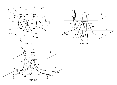
Moving on to Figure 5, this shows a set 46 of generating groups 34 like that
shown in
Figure 3, each generating group 34 comprising a circular array of wind turbine
units 10
15 centred on a respective spar buoy 28 serving as a central hub for the
array. In this
example, the set 46 comprises five such generating groups 34 in two mutually-
staggered rows 48, a first row 48A comprising three generating groups 34
denoted
34A, 34B and 34D and a second parallel row 48B comprising two generating
groups 34
denoted 34C and 34E. Elegantly, this arrangement allows generating groups 34
of one
20 row 48 to share subsea foundations 42 of neighbouring generating groups
34 of the
other row 48, which foundations 42 serve as anchors for the spar buoys 28 of
the
respective generating groups 34. Those shared foundations 42 are disposed
between
the rows 48 as shown.
25 As the turbine mooring lines 44 share the hub anchor lines 40 via link
interfaces, and
as at least some of the foundations 42 are also shared between hub anchor
lines 40,
the installation requires fewer deep-water anchors. This beneficially
declutters the
seabed 38 and helps to protect the installation from fishing or other marine
activities. A
further benefit of this arrangement is to make space for terminal modules such
as
30 towheads 50 of energy storage bundles 52 to be located on the seabed 38
within the
anchor pattern, as shown in Figures 6 and 7.
In this respect, Figures 6 and 7 show elongate energy storage bundles 52 that
terminate in towheads 50 within the anchor pattern of each generating group
34. Such
35 energy storage bundles 52 may employ the principles described in WO
2019/043105,
which disdoses a pumped-storage system having pumping and hydropower
generation
components for, selectively, converting electricity into potential energy by
expelling
CA 03155011 2022-4-14
WO 2021/078899 14
PCT/EP2020/079820
water from within a tank into the surrounding sea and for generating
electricity from an
incoming flow of water re-entering the tank under hydrostatic pressure. The
tank
comprises at least one elongate rigid pipeline that may be lowered to the
seabed 38 as
part of a towable unit or laid on the seabed 38 as a pipe string launched from
a surface
5 vessel.
Conveniently, in the example shown in Figures 6 and 7, each energy storage
bundle 52
comprises: a pumping towhead 50P that supports a set of pumps for expelling
water; a
generating towhead 50G that supports a set of turbo-generator units comprising
water
10 turbines for generating electricity from an incoming flow of water, and
an intermediate
bundle of pipelines that together define a tank or power storage volume and
establish
fluid communication between the pumping towhead 50P and the generating towhead
50G. The pumping towhead 50P of each energy storage bundle 52 is electrically
connected to and configured to be powered by the spar buoy 28 of a respective
one of
15 the generating groups 34 when water is to be expelled from the energy
storage bundle
52 via the pumping towhead 50P. The generating towhead 50G of each energy
storage
bundle 52 is electrically connected to and configured to transmit power
generated by its
turbo-generator units to the spar buoy 28 of another one of the generating
groups 34
when water is allowed to flow back into the energy storage bundle 52 via the
20 generating towhead 50G.
For example, electricity may be generated in a subsea pumped-storage system by
employing the principles described in UK Patent Application GB25713473, which
discloses an underwater turbo-generator unit that comprises a pressure-
resistant shell
25 defining a sealed internal chamber. At least one water inlet extends
through the shell to
effect fluid communication between the chamber and the sea surrounding the
shell. A
turbine is supported within the chamber to turn on a spin axis in response to
admission
of a flow of water into the chamber via the or each water inlet The shell may
be
arranged to maintain a gas-filled space within the chamber, facilitating the
use of a
30 PeIton turbine that turns about a vertical spin axis. The chamber
communicates with,
and drains water into, a fluid storage volume such as a pipeline or bundle
positioned at
a level beneath the chamber.
Figure 6, which is not to scale, shows a generating towhead 50G at an end of
an
35 energy storage bundle 52 lying on the seabed 38. The towhead 50G is
conveniently
close to the vertical central longitudinal axis of the spar buoy 28, and
indeed in this
example is directly beneath the spar buoy 28. A power umbilical 54 hangs from
the
CA 03155011 2022-4-14
WO 2021/078899 15
PCT/EP2020/079820
spar buoy 28 to make electrical connections between electrical equipment on
the spar
buoy 28 and a set of turbo-generator units 56 within the towhead 50G. The
towhead
50G further includes a drainage void or chamber 58 beneath the turbo-generator
units
56 that communicates with the bundle of pipelines 52B extending between the
5 towheads 50P, 50G. A dynamic breather pipe 60 for allowing air to enter
the energy
storage bundle 52 as water is being expelled by the pumping towhead 50P and to
leave the energy storage bundle 52 as water enters the energy storage bundle
52 via
the generating towhead 50G extends from the chamber 58 to the atmosphere above
the surface 62 and is conveniently supported by the spar buoy 28.
A further dynamic power umbilical 64 hangs as a catenary between the raft 22
of the
wind turbine unit 10 and the spar buoy 28. Figure 6 also shows the hub anchor
line 40,
comprising a central section 40C of synthetic rope and upper and lower
sections of
chain 40U, 40L, hanging as a taut leg or catenary between the spar buoy 28 and
a
15 subsea foundation 42 on the seabed 38, and two of the turbine mooring
lines 44 that
hang as taut legs or catenaries from the raft 22 of the wind turbine unit 10.
Each turbine
mooring line 44 comprises an upper section 44U of chain fixed to the wind
turbine unit
10.
20 One of the turbine mooring lines 44 extends from the wind turbine unit
10 radially
inwardly, with respect to the spar buoy 28, to the junction between the
central section
40C and the upper section 40U of the hub anchor line 40. The other of the
turbine
mooring lines 44 extends from the wind turbine unit 10 radially outwardly,
with respect
to the spar buoy 28, to the junction between the central section 40C and the
lower
25 section 40L of the hub anchor line 40.
By way of example, the top of the hub anchor line 40 may be at a depth of
about 50m
beneath the surface 62 and the tops of the turbine mooring lines 44 may be at
a depth
of about 40m beneath the surface 62. Conversely, the seabed 38 may be at a
depth of
30 several hundred metres, for example 600m to 1000m or more.
Figure 7 corresponds to Figure 5 but shows four energy storage bundles 52 that
extend
between, and connect respective pairs of, the five generating groups 34. The
pumping
towheads 50P of the energy storage bundles 52 are adjacent to the spar buoys
28 of
35 the first row 48A of generating groups 34A, 34B and 34D. Conversely, the
generating
towheads 50G of the energy storage bundles 52 are adjacent to the spar buoys
28 of
the second row 4813 of generating groups 34C and 34E.
CA 03155011 2022-4-14
WO 2021/078899 16
PCT/EP2020/079820
Specifically:
a first energy storage bundle 52A extends from generating group 34A to
5 generating group 34C;
a second energy storage bundle 52B extends from generating group 34B to
generating group 34C;
10 a third energy storage bundle 52C extends from generating group
34B to
generating group 34E; and
a fourth energy storage bundle 52D extends from generating group 340 to
generating group 34E.
It will be noted that the towheads 50 of the energy storage bundles 52 are
disposed
close to the vertical longitudinal axes of the spar buoys 28 at the centres of
the
generating groups 34 and indeed may, as shown in Figure 6, lie directly
beneath the
spar buoys 28.
Conveniently, the energy storage bundles 52 are apt to be used not only for
energy
storage but also to effect subsea electrical connections between the spar
buoys 28 of
the rows 48 of generating groups 34. For example, the spar buoys 28 of the
first row
48A of generating groups 34 may conveniently serve as substations for the spar
buoys
25 28 of the second row 48B of generating groups 34, with the first energy
storage bundle
52A providing an electrical connection between the spar buoy 28 of generating
group
34A and the spar buoy 28 of generating group 34C, the second energy storage
bundle
52B providing an electrical connection between the spar buoy 28 of generating
group
34B and the spar buoy 28 of generating group MC and so on.
It will be apparent that the three generating groups 34A, 34B and MD of the
first row
48A provide for generation of power via their wind turbine units 10 and also
for
consumption of power via the pumps in the pumping towheads 50P of the
associated
energy storage bundles 52. In other words, the three generating groups 34A, MB
and
35 340 together provide a focal point for generation of electricity,
effected by conveying
their electrical output to the substations provided by the two generating
groups 34C
and ME of the second row 486, or for energy storage, effected by switching
their
CA 03155011 2022-4-14
WO 2021/078899 17
PCT/EP2020/079820
output to the pumps that consume that electrical output and convert it to
potential
energy.
Conversely, the two generating groups 34C and ME of the second row 48B provide
for
5 generation of power via their wind turbine units 10 and also via the
turbo-generator
units 56 in the generating towheads 50G of the associated energy storage
bundles 52.
The generating groups 34C and 34E also provide for switching their output
either to an
onshore power grid or to the pumps of the pumping towheads 50P that are
located
among the generating groups 34A, 34B and 34D.
Figure 8 shows the set 46 of generating groups 34 situated offshore as part of
a
floating windfarm 66, in which the rows 48 of generating groups 34 within the
set
extend generally parallel to a coastline 68. A sloping seabed 38 shelving
steeply away
from the coastline is represented here by contour lines 70. One contour line
70A
15 representing a water depth of, for example, 800m extends through the
three generating
groups 34A134B and 34D of the first row 48A further from the coastline 68. The
other
contour line 70B representing a water depth of, for example, 600m extends
through the
two generating groups 34C and 34E of the second row 48B closer to the
coastline 68.
Thus, efficiently, the pumping towheads 50P of the energy storage bundles 52
are at a
20 greater water depth than the generating towheads 50G of the energy
storage bundles
52.
In this example, the spar buoys 28 of the two generating groups 34C and 34E of
the
second row 48B serve as substations for the three generating groups MA, 34B
and
25 34D of the first row. The two spar buoys 28 that serve as substations
are connected to
an onshore power grid 72 by respective high-voltage links 74 that cross the
coastline
66. The high-voltage links 74 are suitably located underwater and may, on
land, be
located underground.
30 Turning next to Figures 9 to 11, these drawings exemplify the electrical
distribution
system of the windfarm 66 shown in Figure 8.
In the electrical block diagram of Figure 9, the generating groups 34A, 34B,
34C, MD
and ME each comprise an array of eight wind turbine units 10 connected to
associated
35 switchgear 76 housed in the respective spar buoys 28. Dry splice
connections are
made between the wind turbine units 10 and the switchgear 76, which are all
topside
above the surface 62 or at least are housed in a dry environment.
CA 03155011 2022-4-14
WO 2021/078899 18
PCT/EP2020/079820
The switchgear 76 of generating groups 34A and 343 is connected, via the first
and
second energy storage bundles 52A and 523, to the switchgear 76 of generating
group
34C, which serves as a substation for generating groups 34A and MB.
Conversely, the
5 switchgear 76 of generating group 340 is connected, via the fourth energy
storage
bundle 52D, to the switchgear 76 of generating group 34E, which serves as a
substation for generating group 34D.
The switchgear 76 of generating groups 34A1 MB and 340 is also connected to
10 respective sets of pumps 78, serving as subsea power consumers, located
in the
pumping towheads 50P of the associated energy storage bundles 52.
Specifically, the
switchgear 76 of generating group 34A is connected to the pumping towhead 50P
of
the first energy storage bundle 52A. The switchgear 76 of generating group 34B
is
connected to the pumping towheads 50P of the second and third energy storage
15 bundles 52B and 52C. The switchgear 76 of generating group MD is
connected to the
pumping towhead 50P of the fourth energy storage bundle 52D. VVhilst dry
splice
connections are made to the switchgear 76, wet-mate connections 80 are made to
the
pumps 78 of the pumping towheads 50P.
20 The switchgear 76 of generating groups 34C and 34E is also connected to
respective
sets of turbo-generator units 56, serving as subsea power producers, located
in the
generating towheads 50G of the associated energy storage bundles 52.
Specifically,
the switchgear 76 of generating group MC is connected to the generating
towheads
50G of the first and second energy storage bundles 52A and 52B, whereas the
25 switchgear 76 of generating group 34E is connected to the generating
towheads 50G
of the third and fourth energy storage bundles 52C and 52D. Again, whilst dry
splice
connections are made to the switchgear 76, wet-mate connections 80 are made to
the
turbo-generator units 56 of the generating towheads 50G.
30 The wind turbine units 10 and turbo-generator units 56 of generating
groups 34C and
34E are connected via their switchgear 76 to respective busbars and to
respective
step-up transformers that raise the voltage from 6.6. kV to 132 kV for export
of power
along the high-voltage links 74 leading to shore.
35 Figures 10 and 11 are electrical diagrams that represent generating
groups MB and
34C respectively. Only six wind turbine units 10 are shown in each of these
examples,
CA 03155011 2022-4-14
WO 2021/078899 19
PCT/EP2020/079820
illustrating that there could be any number of wind turbine units 10 in the
arrays of the
generating groups 34.
Each wind turbine unit 10 comprises a generator 82, a transformer 84 and
switchgear
5 86 for controlling a ballast pump 88 to keep the wind turbine unit 10
level under wind
loading as explained previously. Figures 10 and 11 also show the respective
spar
buoys 28 of generating groups 346 and 34C. Each spar buoy 28 is also equipped
with
a ballast pump 90 to control the draft 22 of the buoy 28.
10 In generating group 34B shown in Figure 10, wet-mate connections 80 are
made
subsea between switchgear 76 aboard the spar buoy 28 and the pumping towheads
50P of energy storage bundles 52B and 52C for powering the pumping towheads
50P
in order to expel water from energy storage bundles 526 and 52C. The sets of
pumps
78 of each pumping towhead 50P are shown here with associated transformers 92
and
15 switchgear 94.
Figure 10 also shows how the energy storage bundle 52B electrically connects
the spar
buoy 28 of generating group 348 to the spar buoy 28 of generating group 34C
via wet-
mate connections 80 and power cables 96 extending along the energy storage
bundle
20 52B. In particular, parallel cables 96 are used to transmit power
generated by the
turbine units 10 of generating group 34B to the spar buoy 28 of generating
group 34C
for export, and to transmit power from generating group 34C to the spar buoy
28 of
generating group 34B to support operation of the pumping towheads 50P. .
25 In generating group 34C shown in Figure 11, wet-mate connections 80 are
made
subsea between switchgear 76 aboard the spar buoy 28 and the generating
towheads
50G of energy storage bundles 52A and 52B for transmitting power generated by
the
generating towheads 50G to the spar buoy 28. The sets of turbo-generator units
56 of
each generating towhead 50G are shown here with associated transformers 92 and
30 switchgear 94.
Figure 11 also shows the aforementioned cable connections 96 along energy
storage
bundle 52B for conveying parallel but opposite flows of power generated by the
wind
turbine units 10 and consumed by the pumps 78 associated with generating group
34B.
35 Additionally, Figure 11 shows how energy storage bundle 52A connects the
spar buoy
28 of generating group 34C to the spar buoy 28 of generating group 34A via wet-
mate
connections 80. A cable 96 extending along energy storage bundle 52A thereby
CA 03155011 2022-4-14
WO 2021/078899 20
PCT/EP2020/079820
conveys power generated by the wind turbine units 10 of generating group 34A
to the
spar buoy 28 of generating group 34C.
The spar buoy 2801 generating group 34C houses a busbar 98 and a boost
5 transformer 100 in a dry environment. The generating outputs of the wind
turbine units
of generating groups 34A and 34B and the turbo-generator units 56 of energy
storage bundles 52A and 52B are aggregated at the busbar 98. The boost
transformer
100 steps up the voltage of those aggregated generating outputs to 132 kV for
export
to shore along one of the high-voltage links 74.
The design philosophy of the example shown in Figures 9 to 11 is to minimise
the
amount of equipment that has to be placed subsea and the number of wet-mate
connectors 80 in the system. This involves trade-offs; for example, individual
cables to
each pump 78 could eliminate subsea switching at the cost of each pumping
towhead
15 50P requiring multiple individual cables extending from the surface 62.
Consequently,
the example shown in Figures 9 to 11 employs readily-available subsea
switching and
synchronises supplies on the spar buoys 28 and towheads 50_
As the pumps 78 and turbo-generator units 56 of the energy storage bundles 52
20 preferably have a modular design for ease of maintenance, wet-mate
connectors 80
are particularly apt for the power cables or umbilicals 54 that lead to and
from those
components. Qualified wet-mate connectors are limited to 11kV and 200 A, which
informs the choice of a voltage of 6.6 kV within the windfarm 66 with step-up
to 132 KV
for onward transmission via the high-voltage links 74 to shore.
Thus, the spar buoys 28 of the generating groups 34C and 34E serve as
substations
for all electrical power generated in the windfarm 66, including stepping-up
the voltage
from 6.6 kV within the windfarm 66 to 132 kV for onward transmission to shore.
As
noted above, the spar buoys 28 of the generating groups 34C and 34E provide a
dry
30 environment for the requisite boost transformers 100 and the associated
high-voltage
switchgear 76 and splice connections.
Electrical power generated by the windfarm 66 can be routed either directly to
shore or
to storage in the energy storage bundles 52. In principle, all electrical
power generated
35 by the windfarm may be stored by activating the pumps 78 with 6.6 kV 50
Hz supplies.
Alternatively, the energy storage bundles 52 could be replaced by one or
several
CA 03155011 2022-4-14
WO 2021/078899 21
PCT/EP2020/079820
export cables eventually bundled together to convey electrical power to
successive
hubs, then to a main export cable extending towards an onshore substation.
If there is a base load onshore, the amount of subsea equipment could be
reduced by
5 directing the outputs of individual wind turbine units 10 directly to
shore to support that
base load.
The windfarm 66 may be controlled from onshore, for example via a fibre-optic
communication system that can control power distribution, start-up routines,
10 synchronisation of the individual wind turbines 12, energy storage and
generation
systems. Additionally, monitored data from the pump s 78 and turbines 12 may
be
transmitted onshore and a digital twin may be produced from that data. This
facilitates
life-of-installation monitoring, predictive maintenance and condition
monitoring.
15 When installing the windfarm 66, especially in a remote location, the
use of costly
installation vessels must be optimised. Preferably, the main infrastructure
may be
installed by a specialised vessel in one campaign so that subsequent tow-out
and tie-in
operations can be performed by a lower-specification anchor-handling vessel
with ROV
capability.
An initial campaign using a specialised vessel may, for example, involve:
installing
substation spar buoys 28 and other structures; installing anchors and wet-
parking the
main mooring system for the spar buoys 28; pulling-in and laying high-voltage
links 74
to shore from spar buoys 28 serving as substations; and installing the first
wind turbine
25 units 10. Subsequent installation of spar buoys 28 and umbilicals 54
could be achieved
by a lower-specification vessel to connect lines and umbilicals as wind
turbine units 10
become available.
Installation of the energy storage bundles 52 is optional and in any event
could be
30 delayed because, for example, towing such bundles 52 to the installation
site would not
require a high-specification vessel. Indeed, initially at least, power
generation would be
possible without adding energy storage to the windfarm. This would enable the
windfarm to generate revenue at an early stage, potentially contributing to
the cost of
manufacturing and installing energy storage bundles 52 in the future.
Figure 15 illustrates an alternative layout for a windfarm 67 including a set
46 of
generating groups 34 of wind turbine units 10 in accordance with another
possible
CA 03155011 2022-4-14
WO 2021/078899 22
PCT/EP2020/079820
embodiment of the present invention. The windfarm 67 illustrated in Figure 15
indudes
nine generating groups 34, each generating group 34 including eight wind
turbine units
surrounding a central a spar buoy 28.
5 The generating groups 34 of the windfarm 67 illustrated in Figure 15 are
generally
similar to the generating groups 34 described above in connection with the
windfarm 66
illustrated in Figures 5, 7 and 8. For example, the spar buoy 28 of each group
34 is
connected to the seabed 38 by a plurality of hub anchor lines 40 extending to
subsea
foundations 42, and the wind turbine units 10 of each group 34 are moored by
mooring
10 lines 44 that are each connected to one of the hub anchor lines 40.
However, each of
the wind turbine units 10 in the windfarrn 67 is provided with a set of four
turbine
mooring lines 44 (instead of three turbine mooring lines 44 as shown in
Figures 5, 7
and 8), including two inwardly-extending mooring lines 44 and two outwardly-
extending
mooring lines 44. Each of the inwardly-extending turbine mooring lines 44 is
15 connected to the central spar buoy 28 via the upper section 40U of one
of the spar
buoy's anchor lines 40, and each of the outwardly-extending turbine mooring
lines 44 is
connected to a subsea foundation 42 via the lower section 40L of one of the
spar
buoy's anchor lines 40, as illustrated in Figure 4.
20 As in the windfarm 66 of Figures 5, 7 and 8, within each generating
group, each of the
wind turbine units 10 is electrically connected to the central spar buoy 28
via a dynamic
umbilical 64 (three of which are shown in Figure 15), with the central spar
buoy 28
being configured to act as a central hub for the wind turbine units 10 of its
respective
generating group 34. However, in the windfarm 67 of Figure 15 the wind turbine
units
25 10 are each additionally electrically connected to other wind turbine
units 10 of their
respective generating group 34 by additional hanging cables 65 that extend
between
adjacent pairs of wind turbine units 10 in order to form a network.
As shown in Figure 15, the set 46 of generating groups 34 includes a central
group 34'
30 that is surrounded by a looped array of eight other groups 34" that
together form a
circular arrangement. This is in contrast to the layout of the windfarm of
Figures 5, 7
and 8, in which the generating groups 34 are instead arranged in parallel
rows.
Advantageously, the subsea foundations 42 to which the hub anchor lines 40 of
the
35 central group 34' are attached are each shared by a hub anchor line 40
of one of the
surrounding groups 34", and the surrounding groups 34" also each share subsea
foundations 42 with the adjacent groups 34" in the outer ring, thereby further
reducing
CA 03155011 2022-4-14
WO 2021/078899 23
PCT/EP2020/079820
the total number of subsea foundations 42 required by the windfarm 67 and
decluttering the seabed 38. In the embodiment illustrated in Figure 15 the
subsea
foundations 42 to which the hub anchor lines 40 of the central group 34' are
connected
are more widely spaced and arranged on a wider pitch circle than the subsea
5 foundations 42 to which the hub anchor lines 40 of the surrounding groups
34" are
connected in order to facilitate the sharing of a subsea foundation 42 with
each one of
the surrounding groups 34". However, this need not be the case in all
embodiments.
For example, the spacing of the subsea foundations 42 of the central group 34'
could
be the same as the spacing of the subsea foundations 42 of the surrounding
groups
10 34" in alternative embodiments in which the number of surrounding groups
34" is
reduced or in which the central group 34' shares subsea foundations 42 with
only some
of the surrounding groups 34".
The spar buoy 28 of each of the surrounding groups 34" is electrically
connected to the
15 spar buoy 28 of the central group 34', which is configured to act as a
substation for the
spar buoys 28 of the surrounding groups 34". The spar buoys 28 of the
surrounding
groups 34" may each be connected to the spar buoy 28 of the central group 34'
using
direct connections 73 as shown in Figure 16, in which the wind turbine units
10, anchor
lines 40 and mooring lines 44 have been omitted for clarity. The connections
may, for
20 example, be provided by dynamic umbilicals, by cables running along the
seabed 38
and/or by energy storage bundles of the type described above in connection
with
Figures 7 and 8. However, in other cases one or more of the surrounding groups
34"
may be connected to the spar buoy 28 of the central group 34' indirectly via
one or
more of the other surrounding groups 34". The spar buoy 28 of the central
group 34' is
25 further connected to a high-voltage link 74 which is configured to
export power from the
windfarm 67, for example to an onshore grid (not shown).
Turning finally to Figures 12 to 14, these drawings show various alternative
arrangements within the inventive concept for mooring and connecting central
hubs
30 and wind turbine units 10 of generating groups 34. For example, whilst
the
arrangements shown in Figures 12 and 13 have a spar buoy 28 serving as a
central
hub, Figure 14 shows that the central hub could instead be a tension-leg
platform 102.
In Figure 12, a spar buoy 28 floating at the surface 62 is moored by three hub
anchor
35 lines 40 that extend to respective subsea foundations 42 embedded in the
seabed 38.
In this example, upper and lower sections 40U, 40L of chain are optional. A
wind
turbine unit 10 is moored by three turbine mooring lines 44. The hub anchor
lines 40
CA 03155011 2022-4-14
WO 2021/078899 24
PCT/EP2020/079820
and the turbine mooring lines 44 could be substantially or entirely of polymer
rope. Two
of the turbine mooring lines 44 extend to, and share, the subsea foundations
42 of two
of the hub anchor lines 40. The other turbine mooring line 44 is connected
directly to
the wind turbine unit 10 and the spar buoy 28 as a radial line.
Figure 12 also shows a dynamic umbilical 64 extending between the wind turbine
unit
and the spar buoy 28 and an export cable 104 extending from the spar buoy 28
to
export power, for example to another generating group 34 or directly to the
shore.
10 In Figure 13, the spar buoy 28 floating at the surface 62
is moored by four hub anchor
lines 40 that extend to respective subsea foundations 42 embedded in the
seabed 38.
In this example, each hub anchor line 40 has a central section 40C of polymer
rope
and upper and lower sections 40U, 40L of chain. Again, the wind turbine unit
10 is
moored by three turbine mooring lines 44. Two of the turbine mooring lines 44
extend
to, and intersect, respective ones of the hub anchor lines 40 at the junction
between
the central section 40C and the lower section 40L, hence sharing their lower
sections
40L of chain. The other turbine mooring line 44 intersects one of the hub
anchor lines
40 at the junction between its central section 40C and its upper section 40U,
hence
sharing its upper section 40U of chain adjoining the spar buoy 28.
Figure 13 also shows a dynamic umbilical 64 extending between the wind turbine
unit
10 and the spar buoy 28 and an export umbilical 54 that hangs from the spar
buoy 28
to export power along an energy storage bundle 52 that lies on the seabed 38.
The tension-leg platform 102 shown in Figure 14 comprises four taut legs 106
in this
example, each extending to a respective subsea foundation 42 embedded in the
seabed 38. Here, the wind turbine unit 10 is moored by four turbine mooring
lines 44.
Two of the turbine mooring lines 44 extend to, and share, the subsea
foundations 42 of
two of the legs 106. A third turbine mooring line 44 extends to an additional
subsea
foundation 42. The fourth turbine mooring line 44 is connected directly to the
wind
turbine unit 10 and to the platform 102 as a radial line.
Again, Figure 14 also shows a dynamic umbilical 64 extending between the wind
turbine unit 10 and the platform 102 and an export umbilical 54 that hangs
from the
platform 102 to export power along an energy storage bundle 52 that lies on
the
seabed 38.
CA 03155011 2022-4-14
WO 2021/078899 25
PCT/EP2020/079820
Many other variations are possible without departing from the inventive
concept. For
example, it would be possible for a turbine mooring line 44 to extend to a
subsea
foundation 42 and to be fixed to the subsea foundation 42 in parallel to a hub
anchor
line 40, or to be fixed to a separate subsea foundation 42. Similarly, it
would be
5 possible for a turbine mooring line 44 to extend to a central hub such as
a spar buoy 28
and to be fixed to that hub in parallel to a hub anchor line 40. In those
cases, each
turbine mooring line 44 may comprise a central section 40C of steel wire or
synthetic
rope and upper and/or lower sections 40U, 40L of steel chain.
10 The invention could be used with wind turbines 12 that turn about a
substantially
vertical axis rather than a substantially horizontal axis. The invention could
also be
used with other power-generating machines driven by tides or waves, such as
tidal
turbines, instead of or in addition to wind turbines 12. For example, the spar
buoy 28 or
other central hub and/or the supporting rafts 22 of the wind turbines 12 could
support
15 such other power-generating machines. An additional wind turbine 12
could be
installed on the spar buoy 28 or other central hub. Similarly, the spar buoy
28 or other
central hub and/or the surrounding wind turbine units 10 could additionally
support
equipment for solar power generation.
CA 03155011 2022-4-14