Sélection de la langue

Search

Sommaire du brevet 3155813 

Énoncé de désistement de responsabilité concernant l'information provenant de tiers

Une partie des informations de ce site Web a été fournie par des sources externes. Le gouvernement du Canada n'assume aucune responsabilité concernant la précision, l'actualité ou la fiabilité des informations fournies par les sources externes. Les utilisateurs qui désirent employer cette information devraient consulter directement la source des informations. Le contenu fourni par les sources externes n'est pas assujetti aux exigences sur les langues officielles, la protection des renseignements personnels et l'accessibilité.

Disponibilité de l'Abrégé et des Revendications

L'apparition de différences dans le texte et l'image des Revendications et de l'Abrégé dépend du moment auquel le document est publié. Les textes des Revendications et de l'Abrégé sont affichés :

  • lorsque la demande peut être examinée par le public;
  • lorsque le brevet est émis (délivrance).
(12) Brevet: (11) CA 3155813
(54) Titre français: MACHINE POUR APPLIQUER DES ETIQUETTES OU D'AUTRES MARQUES SUR DES CONTENEURS
(54) Titre anglais: MACHINE FOR APPLYING LABELS OR OTHER MARKINGS TO CONTAINERS
Statut: Accordé et délivré
Données bibliographiques
(51) Classification internationale des brevets (CIB):
  • B65C 3/14 (2006.01)
  • B65C 3/08 (2006.01)
  • B65C 9/02 (2006.01)
  • B65C 9/06 (2006.01)
  • B65C 9/20 (2006.01)
(72) Inventeurs :
  • BELIVACQUA, G (Italie)
(73) Titulaires :
  • ACCRAPLY, LLC, A BARRY-WEHMILLER PACKAGING COMPANY
(71) Demandeurs :
  • ACCRAPLY, LLC, A BARRY-WEHMILLER PACKAGING COMPANY (Etats-Unis d'Amérique)
(74) Agent: WILSON LUE LLP
(74) Co-agent:
(45) Délivré: 2022-11-22
(86) Date de dépôt PCT: 2020-12-22
(87) Mise à la disponibilité du public: 2021-07-08
Requête d'examen: 2022-04-22
Licence disponible: S.O.
Cédé au domaine public: S.O.
(25) Langue des documents déposés: Anglais

Traité de coopération en matière de brevets (PCT): Oui
(86) Numéro de la demande PCT: PCT/US2020/066675
(87) Numéro de publication internationale PCT: US2020066675
(85) Entrée nationale: 2022-04-22

(30) Données de priorité de la demande:
Numéro de la demande Pays / territoire Date
62/954,777 (Etats-Unis d'Amérique) 2019-12-30

Abrégés

Abrégé français

La présente invention concerne une machine (10, 224, 258, 274, 292, 310) qui est sélectivement opérationnelle pour appliquer des marquages tels que des étiquettes, des manchons, des décorations et des indices sur des récipients (58, 130, 162, 254). La machine comprend un transporteur inférieur (LC) (14) et un transporteur supérieur (UC) (28). Des navettes LC (46) sont sélectivement mobiles autour d'une piste LC (16). Des navettes UC (52) sont sélectivement mobiles autour d'une piste UC (30). Les navettes LC et UC sont sélectivement mobiles pour venir en prise avec un récipient verticalement intermédiaire entre les navettes LC et UC respectives. Dans la position de mise en prise de récipient, chaque récipient est sélectivement mobile de manière rotative et linéaire de façon à être positionné en prise avec des applicateurs (108, 256, 296, 298, 300, 314, 316, 318, 320, 322, 324). Les applicateurs sont sélectivement opérationnels pour appliquer des marquages sur des récipients respectifs en prise opérationnelle avec ceux-ci d'une manière précise et reproductible.


Abrégé anglais

A machine (10, 224, 258, 274, 292, 310) is selectively operative to apply markings such as labels, sleeves, decorations and indicia to containers (58, 130, 162, 254). The machine includes a lower conveyor (LC) (14) and an upper conveyor (UC) (28). LC shuttles (46) are selectively movable around an LC track (16). UC shuttles (52) are selectively movable around a UC track (30). The LC and UC shuttles are selectively movable to engage a container vertically intermediate of respective LC and UC shuttles. In the container engaged position each container is selectively rotatably and linearly movable so as to be positioned in engagement with applicators (108, 256, 296, 298, 300, 314, 316, 318, 320, 322, 324). The applicators are selectively operative to apply markings to respective containers in operative engagement therewith in a precise and repeatable manner.

Revendications

Note : Les revendications sont présentées dans la langue officielle dans laquelle elles ont été soumises.


Claims
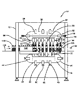
1 . Apparatus comprising:
a machine that is operative to apply markings to containers,
wherein each of the containers include
a bottom end, and
an upper portion disposed away from the bottom end,
the machine including:
a lower conveyor (LC), wherein the LC includes
a continuous LC track, wherein the LC track includes
a substantially linearly straight, horizontally extending LC labeling
track portion,
wherein the LC labeling track portion extends from an LC
inlet end to an LC outlet end,
a return LC track portion, wherein the return LC track portion
extends
vertically below the LC labeling track portion, and
3 1

from the LC outlet end to the LC inlet end,
an upper conveyor (UC), wherein the UC includes
a continuous UC track, wherein the UC track includes
a substantially linearly straight, horizontally extending UC labeling
track portion,
wherein the UC labeling track portion
is disposed vertically above and in aligned relation with the
LC labeling track portion,
extends intermediate of a UC inlet end and a UC outlet end,
a return UC track portion,
wherein the return UC track portion extends
vertically above the UC labeling track portion, and
from the UC outlet end to the UC inlet end,
at least one LC shuttle,
wherein each LC shuttle
32

is in operative connection with the LC,
is movable along the entire LC track,
includes a container engagement platform,
wherein the container engagement platform is configured to
engage the bottom end of only one container, and
is rotatably movable relative to the respective LC shuttle,
at least one UC shuttle,
wherein each UC shuttle
is in operative connection with the UC,
is movable along the entire UC track,
includes a container engagement fixture thereon,
wherein the container engagement fixture is configured to
engage the upper portion of only one container,
an applicator,
a movable applicator mount, wherein the applicator is in operatively supported
connection with the applicator mount,
33

wherein the applicator
is in an applicator position, wherein the applicator position is
disposed adjacent to the LC labeling track portion and the UC
labeling track portion,
horizontally intermediate of the LC inlet end and the LC outlet
end, and
selectively variable from the LC inlet end in a first direction along
the LC labeling track and the UC labeling track responsive to
movement of the applicator mount,
is operative to apply at least one marking to a container in operative
engagement with the applicator in the applicator position,
wherein the machine is operative to
move one respective LC shuttle and one respective UC shuttle into vertically
aligned relation to engage the container in a shuttle engaged position,
wherein in
the shuttle engaged position the container is vertically between and in
operative
engagement with both the respective LC shuttle and the respective UC shuttle,
wherein in the shuttle engaged position the bottom end of the container is
in operatively engaged relation with the container engagement platform of
34

the respective LC shuttle and the upper end of the container is in
operatively engaged relation with the container engagement fixture of the
respective UC shuttle,
move the respective LC shuttle and the respective UC shuttle in coordinated
relation in the first direction while holding the container in the shuttle
engaged
position, into the applicator position wherein the container is in operative
engagement with the applicator,
operate the applicator to apply at least one marking to the container in the
applicator position and while the container is in the shuttle engaged
position,
move the marked container in the shuttle engaged position in the first
direction
away from the applicator position toward the LC outlet end, and
release the container from operative engagement with the respective LC shuttle
and the respective UC shuttle.
2. The apparatus according to claim 1
and further comprising:
at least one jack, wherein the at least one jack is in operative connection
with the
LC and the UC,

wherein the at least one jack is operative to selectively change a vertical
distance
between the LC labeling track portion and the UC labeling track portion.
3. The apparatus according to claim 1
and further comprising:
a drive, wherein the drive is in operative connection with the container
engagement platform,
a feature sensor, wherein the feature sensor is in operative connection with
the
drive,
wherein the feature sensor is operative to sense at least one feature of the
container and wherein the drive is operative to rotatably position the
container
through rotation of the container engagement platform responsive at least in
part
to the sensed at least one feature.
4. The apparatus according to claim 1
wherein the applicator mount enables the applicator position to be selectively
variable in a transverse direction, wherein the transverse direction is
perpendicular to the first direction.
5. The apparatus according to claim 1
36

wherein the container engagement fixture is rotatably movable relative to the
respective UC shuttle,
wherein in the shuttle engaged position the container engagement fixture is
rotatable coaxially with the container engagement platform,
wherein the container engagement fixture and the container engagement platform
each rotate while the applicator is operative to apply the at least one
marking to
the container.
6. The apparatus according to claim 1
and further comprising:
a controller, wherein the controller includes control circuitry,
at least one incoming container position sensor,
wherein the at least one incoming container position sensor is operative to
sense the container proximate to the LC inlet end and the UC inlet end,
wherein the controller is in operative connection with the LC, the UC and the
at
least one incoming container position sensor,
wherein the controller is operative to cause the respective LC shuttle and
respective UC shuttle to concurrently move about the respective LC track and
UC
track to operatively engage the container in the shuttle engaged position.
37

7. The apparatus according to claim 1
wherein at least one of each LC shuttle or UC shuttle includes a respective
shuttle
drive,
wherein each respective LC shuttle or UC shuttle is selectively movable on the
respective LC track or UC track in both the first direction and a second
direction
opposed of the first direction responsive to operation of the respective
shuttle
drive independent of movement of every other respective LC shuttle or UC
shuttle.
8. The apparatus according to claim 1
wherein at least one of the LC or the UC includes a movable continuous drive
chain,
wherein the drive chain extends along the respective LC track or UC track,
an actuator in operative connection with each respective at least one LC
shuttle or
UC shuttle, wherein the actuator is operative to selectively operatively
engage and
disengage the respective LC shuttle or UC shuttle and the drive chain,
wherein each of the at least one respective LC shuttle or UC shuttle is
enabled to
be selectively operatively disengaged from the drive chain and engaged in
operative connection with the drive chain and moved about the respective LC
track or UC track responsive to chain movement.
9. The apparatus according to claim 1
38

wherein the machine includes a frame, wherein the frame includes at least one
horizontally extending strut,
wherein the applicator mount is movable along the first direction in operative
connection with the at least one horizontally extending strut,
and further comprising at least one releasable clamp, wherein the at least one
releasable clamp is in operative connection with the applicator mount, wherein
the
at least one clamp is selectively engageable in fixed operative engagement
with
the at least one horizontally extending strut,
wherein when the clamp is in fixed operative engagement with the at least one
horizontally extending strut the applicator is held in a fixed position along
the first
direction relative to the LC and the UC.
10. The apparatus according to claim 1
wherein the machine further includes a frame,
wherein the applicator mount is movably mounted in operatively supported
connection with the frame,
wherein the applicator mount is selectively movable in operatively supported
connection with the frame along the first direction and along a second
direction
transverse of the first direction.
1 1. The apparatus according to claim 1
39

wherein the applicator includes at least one of
a pressure sensitive labeling station,
a cold glue labeling station,
a cut and stack hot melt labeling station,
a roll fed hot melt labeling station,
a sleeve labeling station, and
a printing station.
12. The apparatus according to claim 10
and further comprising a releasable clamp,
wherein the releasable clamp is in operative connection with the
applicator mount and the frame,
wherein the releasable clamp is changeable between a movable condition
and a fixed engaged condition, wherein in the movable condition of the
clamp the applicator mount is movable relative to the frame at least along
the first direction, and in the engaged condition of the clamp the applicator
mount is held in fixed operative engagement with the frame.
13. The apparatus according to claim 12

wherein the frame includes at least one horizontally extending strut,
wherein in the movable condition of the clamp, the applicator mount is movable
along the first direction in operatively supported connection with the at
least one
horizontally extending strut.
14. Apparatus comprising:
a machine that is operative to apply markings to containers,
wherein each of the containers include
a bottom end, and
an upper portion disposed away from the bottom end,
the machine including:
a lower conveyor (LC), wherein the LC includes
a continuous LC track, wherein the LC track includes
a substantially linearly straight, horizontally extending LC labeling
track portion,
wherein the LC labeling track portion extends from an LC
inlet end to an LC outlet end,
41

a return LC track portion, wherein the return LC track portion
extends
vertically below the LC labeling track portion, and
from the LC outlet end to the LC inlet end,
an upper conveyor (UC), wherein the UC includes
a continuous UC track, wherein the UC track includes
a substantially linearly straight, horizontally extending UC labeling
track portion,
wherein the UC labeling track portion
is disposed vertically above and in aligned relation with the
LC labeling track portion,
extends intermediate of a UC inlet end and a UC outlet end,
a return UC track portion,
wherein the return UC track portion extends
vertically above the UC labeling track portion, and
from the UC outlet end to the UC inlet end,
42

at least one LC shuttle,
wherein each LC shuttle
is in operative connection with the LC,
is movable along the entire LC track,
includes a container engagement platform,
wherein the container engagement platform is configured to
engage the bottom end of only one container, and
is rotatably movable relative to the respective LC shuttle,
at least one UC shuttle,
wherein each UC shuttle
is in operative connection with the UC,
is movable along the entire UC track,
includes a container engagement fixture thereon,
wherein the container engagement fixture is configured to
engage the upper portion of only one container,
43

an applicator, wherein the applicator
is in an applicator position, wherein the applicator position is
disposed adjacent to the LC labeling track portion and the UC
labeling track portion,
horizontally intermediate of the LC inlet end and the LC outlet
end,
is operative to apply at least one marking to a container in operative
engagement with the applicator in the applicator position,
wherein the machine is operative to
move one respective LC shuttle and one respective UC shuttle into vertically
aligned relation to engage the container in a shuttle engaged position,
wherein in
the shuttle engaged position the container is vertically between and in
operative
engagement with both the respective LC shuttle and the respective UC shuttle,
wherein in the shuttle engaged position the bottom end of the container is
in operatively engaged relation with the container engagement platform of
the respective LC shuttle and the upper end of the container is in
operatively engaged relation with the container engagement fixture of the
respective UC shuttle,
44

move the respective LC shuttle and the respective UC shuttle in coordinated
relation in a first direction along the LC labeling track and UC labeling
track
respectively while holding the container in the shuttle engaged position, into
the
applicator position wherein the container is in operative engagement with the
applicator,
operate the applicator to apply at least one marking to the container in the
applicator position and while the container is in the shuttle engaged
position,
move the marked container in the shuttle engaged position in the first
direction
away from the applicator position toward the LC outlet end, and
release the container from operative engagement with the respective LC shuttle
and the respective UC shuttle,
wherein the machine further includes
at least one optical sensor, wherein the at least one optical sensor is
in operative connection with a controller including control
circuitry,
disposed in the first direction from the applicator position,
operative to sense at least one optical characteristic of the at least
one marking on the container applied by the applicator,

wherein the control circuitry includes at least one data store,
wherein the at least one data store includes quality data, wherein the
quality data corresponds to at least one of
a proper container application of the at least one marking,
an improper container application of the at least one marking,
wherein the controller is operative to cause rotation of the container in
engagement with the container engagement platform while the at least one
optical
characteristic is sensed by the at least one optical sensor,
wherein the controller is operative responsive at least in part to the at
least one
optical characteristic sensed by the at least one optical sensor while the
container
is rotated and the quality data to cause
a determination of an improper container application of the at least one
marking on the container,
responsive at least in part to the determination, generation of at least one
signal that is operative at least in part to cause the container to be
segregated from other containers that have the at least one marking
properly applied.
15. The apparatus according to claim 14
46

and further comprising:
a movable applicator mount, wherein the applicator is in operatively supported
connection with the applicator mount,
wherein the applicator position is selectively variable from the LC inlet end
along
the first direction responsive to movement of the applicator mount.
16. The apparatus according to claim 14
and further comprising:
a wireless transceiver in operative connection with the controller,
wherein each of the at least one LC shuttle or the at least one UC shuttle
includes
a shuttle wireless transceiver,
wherein each of the at least one LC shuttle or the at least one UC shuttle is
operative to move along the respective LC track or UC track responsive at
least in
part to wireless communication with the controller.
17. Apparatus comprising:
a machine that is operative to apply markings to containers,
wherein each of the containers include
a bottom end, and
47

an upper portion disposed away from the bottom end,
the machine including:
a lower conveyor (LC), wherein the LC includes
a continuous LC track, wherein the LC track includes
a substantially linearly straight, horizontally extending LC labeling
track portion,
wherein the LC labeling track portion extends from an LC
inlet end to an LC outlet end,
a return LC track portion, wherein the return LC track portion
extends
vertically below the LC labeling track portion, and
from the LC outlet end to the LC inlet end,
an upper conveyor (UC), wherein the UC includes
a continuous UC track, wherein the UC track includes
a substantially linearly straight, horizontally extending UC labeling
track portion,
48

wherein the UC labeling track portion
is disposed vertically above and in aligned relation with the
LC labeling track portion,
extends intermediate of a UC inlet end and a UC outlet end,
a return UC track portion,
wherein the return UC track portion extends
vertically above the UC labeling track portion, and
from the UC outlet end to the UC inlet end,
at least one LC shuttle, wherein each LC shuttle
is in operative connection with the LC and
is movable along the entire LC track,
wherein each LC shuttle includes
a shuttle location sensor, wherein the shuttle location sensor is operative to
provide signals usable to determine a current location of the LC shuttle on
the LC track,
a container engagement platform
49

wherein the container engagement platform is configured to
engage the bottom end of only one container, and
is rotatably movable relative to the respective LC shuttle,
a drive
wherein the drive is in operative connection with the container
engagement platform, and is configured to selectively rotate the
container engagement platform,
a wireless transceiver, wherein the wireless transceiver is in operative
connection with the drive,
wherein the drive is operative to rotate the container engagement
platform responsive at least in part to wireless signals received by
the wireless transceiver,
at least one UC shuttle, wherein each UC shuttle
is in operative connection with the UC,
is movable along the entire UC track,
includes a container engagement fixture thereon,
wherein the container engagement fixture is configured to engage
the upper portion of only one container
an applicator, wherein the applicator
,

is in an applicator position, wherein the applicator position is
disposed adjacent to the LC labeling track portion and the UC
labeling track portion, and
horizontally intermediate of the LC inlet end and the LC outlet
end,
is operative to apply at least one marking to a container in operative
engagement with the applicator in the applicator position,
wherein the machine is operative to
move one respective LC shuttle and one respective UC shuttle into vertically
aligned relation to engage the container in a shuttle engaged position,
wherein in
the shuttle engaged position the container is vertically between and in
operative
engagement with both the respective LC shuttle and the respective UC shuttle,
wherein in the shuttle engaged position the bottom end of the container is
in operatively engaged relation with the container engagement platform of
the respective LC shuttle and the upper end of the respective container is
in operatively engaged relation with the container engagement fixture of
the respective UC shuttle,
move the respective LC shuttle and the respective UC shuttle in coordinated
relation in a first direction along the LC labeling track and UC labeling
track
1

respectively while holding the container in the shuttle engaged position, into
the
applicator position wherein the container is in operative engagement with the
applicator,
operate the applicator to apply at least one marking to the container in the
applicator position and while the container is in the shuttle engaged
position,
move the marked container in the shuttle engaged position in the first
direction
away from the applicator position toward the LC outlet end, and
release the container from operative engagement with the respective LC shuttle
and the respective UC shuttle.
18. The apparatus according to claim 17
and further comprising:
at least one optical sensor, wherein the at least one optical sensor is in
operative
connection with a controller including control circuitry and is disposed in
the first
direction from the applicator position,
wherein the at least one optical sensor is operative to sense at least one
optical characteristic of the marking on the container applied by the
applicator,
wherein the control circuitry includes a data store,
52

wherein the data store includes quality data, wherein the quality data
corresponds to at least one of
a proper container application of the marking,
an improper container application of the marking,
wherein the controller is operative to cause rotation of the container in
engagement with the container engagement platform while the at least one
optical
characteristic is sensed by the at least one optical sensor,
wherein the controller is operative responsive at least in part to the at
least one
optical characteristic sensed by the at least one optical sensor while the
container
is rotated and the quality data to cause
a determination of an improper container application of the at least one
marking on the container,
responsive at least in part to the determination, generation of at least one
signal that is operative to cause the container to be segregated from other
containers having the at least one marking applied properly.
19. The apparatus according to claim 17
wherein the drive is further operative to vertically move the container
engagement
platform responsive at least in part to the wireless signals.
53

20. The apparatus according to claim 17
wherein the drive is operative to rotate the container engagement platform
while
the applicator is operative to apply the at least one marking to the
container.
21. The apparatus according to claim 17
wherein the container engagement fixture is rotatable relative to the
respective
UC shuttle,
wherein each UC shuttle further includes
a further drive,
wherein the further drive is in operative connection with the container
engagement fixture,
wherein the further drive is operative to selectively rotate the container
engagement fixture.
22. The apparatus according to claim 17
wherein each LC shuttle further includes an LC shuttle drive, wherein the LC
shuttle drive is operative to selectively move the LC shuttle relative to the
LC
shuttle track,
wherein the LC shuttle drive is in operative connection with the wireless
transceiver,
54

wherein the LC shuttle drive is operative to move the LC shuttle relative
to the LC shuttle track responsive at least in part to wireless signals
received through the wireless transceiver.
23. Apparatus comprising:
a machine that is operative to apply markings to containers,
wherein each of the containers include
a bottom end, and
an upper portion disposed away from the bottom end,
the machine including:
a lower conveyor (LC), wherein the LC includes
a continuous LC track, wherein the LC track includes
a substantially linearly straight, horizontally extending LC labeling
track portion,
wherein the LC labeling track portion extends from an LC
inlet end to an LC outlet end,

a return LC track portion, wherein the return LC track portion
extends
vertically below the LC labeling track portion, and
from the LC outlet end to the LC inlet end,
an upper conveyor (UC), wherein the UC includes
a continuous UC track, wherein the UC track includes
a substantially linearly straight, horizontally extending UC labeling
track portion,
wherein the UC labeling track portion
is disposed vertically above and in aligned relation with the
LC labeling track portion,
extends intermediate of a UC inlet end and a UC outlet end,
a return UC track portion,
wherein the return UC track portion extends
vertically above the UC labeling track portion, and
from the UC outlet end to the UC inlet end,
56

at least one LC shuttle, wherein each LC shuttle
is in operative connection with the LC and
is movable along the entire LC track,
wherein each LC shuttle includes
a container engagement platform,
wherein the container engagement platform is configured to
engage the bottom end of only one container, and
is rotatably movable relative to the respective LC shuttle,
a drive
wherein the drive is in operative connection with the container
engagement platform, and is configured to selectively rotate the
container engagement platform,
a wireless transceiver, wherein the wireless transceiver is in operative
connection with the drive,
wherein the drive is operative to rotate the container engagement
platform responsive at least in part to wireless signals received by
the wireless transceiver,
at least one UC shuttle, wherein each UC shuttle
57

is in operative connection with the UC,
is movable along the entire UC track,
includes a container engagement fixture thereon,
wherein the container engagement fixture is configured to engage
the upper portion of only one container,
includes a UC shuttle drive, wherein the UC shuttle drive is operative to
selectively move the UC shuttle relative to the UC shuttle track,
includes a further wireless transceiver, wherein the UC shuttle drive is in
operative connection with the further wireless transceiver, wherein the UC
shuttle drive is operative to move the UC shuttle relative to the UC shuttle
track responsive at least in part to wireless signals received through the
further wireless transceiver,
an applicator, wherein the applicator
is in an applicator position, wherein the applicator position is
disposed adjacent to the LC labeling track portion and the UC
labeling track portion, and
horizontally intermediate of the LC inlet end and the LC outlet
end,
58

is operative to apply at least one marking to a container in operative
engagement with the applicator in the applicator position,
wherein the machine is operative to
move one respective LC shuttle and one respective UC shuttle into vertically
aligned relation to engage the container in a shuttle engaged position,
wherein in
the shuttle engaged position the container is vertically between and in
operative
engagement with both the respective LC shuttle and the respective UC shuttle,
wherein in the shuttle engaged position the bottom end of the container is
in operatively engaged relation with the container engagement platform of
the respective LC shuttle and the upper end of the respective container is
in operatively engaged relation with the container engagement fixture of
the respective UC shuttle,
move the respective LC shuttle and UC shuttle in coordinated relation in a
first
direction along the LC labeling track and UC labeling track respectively while
holding the container in the shuttle engaged position, into the applicator
position
wherein the container is in operative engagement with the applicator,
operate the applicator to apply at least one marking to the container in the
applicator position and while the container is in the shuttle engaged
position,
move the marked container in the shuttle engaged position in the first
direction
away from the applicator position toward the LC outlet end, and
59

release the container from operative engagement with the respective LC shuttle
and the respective UC shuttle.
24. Apparatus comprising:
a machine that is operative to apply markings to containers,
wherein each of the containers include
a bottom end, and
an upper portion disposed away from the bottom end,
the machine including:
a lower conveyor (LC), wherein the LC includes
a continuous LC track, wherein the LC track includes
a substantially linearly straight, horizontally extending LC labeling
track portion,
wherein the LC labeling track portion extends from an LC
inlet end to an LC outlet end,
a return LC track portion, wherein the return LC track portion
extends

vertically below the LC labeling track portion, and
from the LC outlet end to the LC inlet end,
an upper conveyor (UC), wherein the UC includes
a continuous UC track, wherein the UC track includes
a substantially linearly straight, horizontally extending UC labeling
track portion,
wherein the UC labeling track portion
is disposed vertically above and in aligned relation with the
LC labeling track portion,
extends intermediate of a UC inlet end and a UC outlet end,
a return UC track portion,
wherein the return UC track portion extends
vertically above the UC labeling track portion, and
from the UC outlet end to the UC inlet end,
at least one LC shuttle, wherein each LC shuttle
61

is in operative connection with the LC and
is movable along the entire LC track,
wherein each LC shuttle includes
a container engagement platform
wherein the container engagement platform is configured to
engage the bottom end of only one container, and
is rotatably movable relative to the respective LC shuttle,
at least one drive
wherein the at least one drive is in operative connection with the
container engagement platform, and is configured to selectively
rotate and vertically move the container engagement platform,
a wireless transceiver, wherein the wireless transceiver is in operative
connection with the at least one drive,
wherein the at least one drive is operative to cause rotation and
vertical movement of the container engagement platform
responsive at least in part to wireless signals received by the
wireless transceiver,
at least one UC shuttle, wherein each UC shuttle
is in operative connection with the UC,
62

is movable along the entire UC track,
includes a container engagement fixture thereon,
wherein the container engagement fixture is configured to engage
the upper portion of only one container
an applicator, wherein the applicator
is in an applicator position, wherein the applicator position is
disposed adjacent to the LC labeling track portion and the UC
labeling track portion, and
horizontally intermediate of the LC inlet end and the LC outlet
end,
is operative to apply at least one marking to a container in operative
engagement with the applicator in the applicator position,
wherein the machine is operative to
move one respective LC shuttle and one respective UC shuttle into vertically
aligned relation to engage the container in a shuttle engaged position,
wherein in
the shuttle engaged position the container is vertically between and in
operative
engagement with both the respective LC shuttle and the respective UC shuttle,
63

wherein in the shuttle engaged position the bottom end of the container is
in operatively engaged relation with the container engagement platform of
the respective LC shuttle and the upper end of the container is in
operatively engaged relation with the container engagement fixture of the
respective UC shuttle,
move the respective LC shuttle and the respective UC shuttle in coordinated
relation in a first direction along the LC labeling track and UC labeling
track
respectively while holding the container in the shuttle engaged position, into
the
applicator position wherein the container is in operative engagement with the
applicator,
operate the applicator to apply at least one marking to the container in the
applicator position and while the container is in the shuttle engaged
position,
move the marked container in the shuttle engaged position in the first
direction
away from the applicator position toward the LC outlet end, and
release the container from operative engagement with the respective LC shuttle
and the respective UC shuttle.
25. Apparatus comprising:
a machine that is operative to apply markings to containers,
wherein each of the containers include
64

a bottom end, and
an upper portion disposed away from the bottom end,
the machine including:
a lower conveyor (LC), wherein the LC includes
a continuous LC track, wherein the LC track includes
a substantially linearly straight, horizontally extending LC labeling
track portion,
wherein the LC labeling track portion extends from an LC
inlet end to an LC outlet end,
a return LC track portion, wherein the return LC track portion
extends
vertically below the LC labeling track portion, and
from the LC outlet end to the LC inlet end,
an upper conveyor (UC), wherein the UC includes
a continuous UC track, wherein the UC track includes

a substantially linearly straight, horizontally extending UC labeling
track portion,
wherein the UC labeling track portion
is disposed vertically above and in aligned relation with the
LC labeling track portion,
extends intermediate of a UC inlet end and a UC outlet end,
a return UC track portion,
wherein the return UC track portion extends
vertically above the UC labeling track portion, and
from the UC outlet end to the UC inlet end,
at least one LC shuttle,
wherein each LC shuttle
is in operative connection with the LC,
is movable along the entire LC track,
includes a container engagement platform,
66

wherein the container engagement platform is configured to
engage the bottom end of only one container, and
is rotatably movable relative to the respective LC shuttle,
at least one UC shuttle,
wherein each UC shuttle
is in operative connection with the UC,
is movable along the entire UC track,
includes a container engagement fixture thereon,
wherein the container engagement fixture is configured to
engage the upper portion of only one container,
a controller, wherein the controller includes control circuitry,
a wireless transceiver in operative connection with the controller,
wherein each of the at least one LC shuttle or the at least one UC shuttle
includes
a shuttle wireless transceiver,
67

wherein each of the at least one LC shuttle or the at least one UC shuttle is
operative to move along the respective LC track or UC track responsive at
least in
part to wireless communication with the controller,
an applicator, wherein the applicator
is in an applicator position, wherein the applicator position is
disposed adjacent to the LC labeling track portion and the UC
labeling track portion,
horizontally intermediate of the LC inlet end and the LC outlet
end,
is operative to apply at least one marking to a container in operative
engagement with the applicator in the applicator position,
wherein the machine is operative to
move one respective LC shuttle and one respective UC shuttle into vertically
aligned relation to engage the container in a shuttle engaged position,
wherein in
the shuttle engaged position the container is vertically between and in
operative
engagement with both the respective LC shuttle and the respective UC shuttle,
wherein in the shuttle engaged position the bottom end of the container is
in operatively engaged relation with the container engagement platform of
68

the respective LC shuttle and the upper end of the container is in
operatively engaged relation with the container engagement fixture of the
respective UC shuttle,
move the respective LC shuttle and the respective UC shuttle in coordinated
relation in a first direction along the LC labeling track and UC labeling
track
respectively while holding the container in the shuttle engaged position, into
the
applicator position wherein the container is in operative engagement with the
applicator,
operate the applicator to apply at least one marking to the container in the
applicator position and while the container is in the shuttle engaged
position,
move the marked container in the shuttle engaged position in the first
direction
away from the applicator position toward the LC outlet end, and
release the container from operative engagement with the respective LC shuttle
and the respective UC shuttle.
26. Apparatus comprising:
a machine that is operative to apply markings to containers,
wherein each of the containers include
a bottom end, and
69

an upper portion disposed away from the bottom end,
the machine including:
a lower conveyor (LC), wherein the LC includes
a continuous LC track, wherein the LC track includes
a substantially linearly straight, horizontally extending LC labeling
track portion,
wherein the LC labeling track portion extends from an LC
inlet end to an LC outlet end,
a return LC track portion, wherein the return LC track portion
extends
vertically below the LC labeling track portion, and
from the LC outlet end to the LC inlet end,
an upper conveyor (UC), wherein the UC includes
a continuous UC track, wherein the UC track includes
a substantially linearly straight, horizontally extending UC labeling
track portion,

wherein the UC labeling track portion
is disposed vertically above and in aligned relation with the
LC labeling track portion,
extends intermediate of a UC inlet end and a UC outlet end,
a return UC track portion,
wherein the return UC track portion extends
vertically above the UC labeling track portion, and
from the UC outlet end to the UC inlet end,
at least one LC shuttle,
wherein each LC shuttle
is in operative connection with the LC,
is movable along the entire LC track,
includes a container engagement platform,
wherein the container engagement platform is configured to
engage the bottom end of only one container, and
71

is rotatably movable relative to the respective LC shuttle,
at least one UC shuttle,
wherein each UC shuttle
is in operative connection with the UC,
is movable along the entire UC track,
includes a container engagement fixture thereon,
wherein the container engagement fixture is configured to
engage the upper portion of only one container,
an applicator, wherein the applicator
is in an applicator position, wherein the applicator position is
disposed adjacent to the LC labeling track portion and the UC
labeling track portion,
horizontally intermediate of the LC inlet end and the LC outlet
end,
is operative to apply at least one marking to a container in operative
engagement with the applicator in the applicator position,
72

a controller, wherein the controller includes control circuitry,
at least one incoming container position sensor,
wherein the at least one incoming container position sensor is operative to
sense the container proximate to the LC inlet end and the UC inlet end,
wherein the controller is in operative connection with the LC, the UC and the
at
least one incoming container position sensor,
wherein the controller is operative to cause the respective LC shuttle and
respective UC shuttle to concurrently move about the respective LC track and
UC
track to operatively engage the container in a shuttle engaged position,
wherein in the shuttle engaged position the container is vertically between
and in
operative engagement with both the respective LC shuttle and the respective UC
shuttle,
wherein in the shuttle engaged position the bottom end of the container is
in operatively engaged relation with the container engagement platform of
the respective LC shuttle and the upper end of the respective container is
in operatively engaged relation with the container engagement fixture of
the respective UC shuttle,
wherein the machine is operative to
73

move the respective LC shuttle and the respective UC shuttle in coordinated
relation in a first direction along the LC labeling track and UC labeling
track
respectively while holding the container in the shuttle engaged position, into
the
applicator position wherein the container is in operative engagement with the
applicator,
operate the applicator to apply at least one marking to the container in the
applicator position and while the container is in the shuttle engaged
position,
move the marked container in the shuttle engaged position in the first
direction
away from the applicator position toward the LC outlet end, and
release the container from operative engagement with the respective LC shuttle
and the respective UC shuttle.
27. Apparatus comprising:
a machine that is operative to apply markings to containers,
wherein each of the containers include
a bottom end, and
an upper portion disposed away from the bottom end,
the machine including:
74

a lower conveyor (LC), wherein the LC includes
a continuous LC track, wherein the LC track includes
a substantially linearly straight, horizontally extending LC labeling
track portion,
wherein the LC labeling track portion extends from an LC
inlet end to an LC outlet end,
a return LC track portion, wherein the return LC track portion
extends
vertically below the LC labeling track portion, and
from the LC outlet end to the LC inlet end,
an upper conveyor (UC), wherein the UC includes
a continuous UC track, wherein the UC track includes
a substantially linearly straight, horizontally extending UC labeling
track portion,
wherein the UC labeling track portion

is disposed vertically above and in aligned relation with the
LC labeling track portion,
extends intermediate of a UC inlet end and a UC outlet end,
a return UC track portion,
wherein the return UC track portion extends
vertically above the UC labeling track portion, and
from the UC outlet end to the UC inlet end,
at least one LC shuttle,
wherein each LC shuttle
is in operative connection with the LC,
is movable along the entire LC track,
includes a container engagement platform,
wherein the container engagement platform is configured to
engage the bottom end of only one container, and
is rotatably movable relative to the respective LC shuttle,
76

at least one UC shuttle,
wherein each UC shuttle
is in operative connection with the UC,
is movable along the entire UC track,
includes a container engagement fixture thereon,
wherein the container engagement fixture is configured to
engage the upper portion of only one container,
wherein each at least one LC shuttle or at least one UC shuttle includes a
respective shuttle drive that is operative to cause movement of the respective
at
least one LC shuttle or at least one UC shuttle,
wherein the respective LC track or UC track includes a spur that extends
adjacent
to the respective LC track or UC track,
wherein the respective at least one LC shuttle or at least one UC shuttle is
movable onto the spur and may remain stationary on the spur while at least one
other LC shuttle or at least one other UC shuttle moves continuously around
the
respective LC track or UC track,
an applicator, wherein the applicator
77

is in an applicator position, wherein the applicator position is
disposed adjacent to the LC labeling track portion and the UC
labeling track portion,
horizontally intermediate of the LC inlet end and the LC outlet
end,
is operative to apply at least one marking to a container in operative
engagement with the applicator in the applicator position,
wherein the machine is operative to
move one respective LC shuttle and one respective UC shuttle into vertically
aligned relation to engage the container in a shuttle engaged position,
wherein in
the shuttle engaged position the container is vertically between and in
operative
engagement with both the respective LC shuttle and the respective UC shuttle,
wherein in the shuttle engaged position the bottom end of the container is
in operatively engaged relation with the container engagement platform of
the respective LC shuttle and the upper end of the container is in
operatively engaged relation with the container engagement fixture of the
respective UC shuttle,
move the respective LC shuttle and the respective UC shuttle in coordinated
relation in a first direction along the LC labeling track and UC labeling
track
78

respectively while holding the container in the shuttle engaged position, into
the
applicator position wherein the container is in operative engagement with the
applicator,
operate the applicator to apply at least one marking to the container in the
applicator position and while the container is in the shuttle engaged
position,
move the marked container in the shuttle engaged position in the first
direction
away from the applicator position toward the LC outlet end, and
release the container from operative engagement with the respective LC shuttle
and the respective UC shuttle.
28. The apparatus according to claim 27
wherein each respective at least one LC shuttle or at least one UC shuttle
includes
a respective battery, wherein the battery is operative to power the respective
shuttle drive,
wherein the machine further includes a battery charger, wherein the battery
charger is configured to charge the respective battery of the at least one LC
shuttle
or at least one UC shuttle on the spur.
29. Apparatus comprising:
a machine that is operative to apply markings to containers,
79

wherein each of the containers include
a bottom end, and
an upper portion disposed away from the bottom end,
the machine including:
a lower conveyor (LC), wherein the LC includes
a continuous LC track, wherein the LC track includes
a substantially linearly straight, horizontally extending LC labeling
track portion,
wherein the LC labeling track portion extends from an LC
inlet end to an LC outlet end,
a return LC track portion, wherein the return LC track portion
extends
vertically below the LC labeling track portion, and
from the LC outlet end to the LC inlet end,
an upper conveyor (UC), wherein the UC includes
a continuous UC track, wherein the UC track includes

a substantially linearly straight, horizontally extending UC labeling
track portion,
wherein the UC labeling track portion
is disposed vertically above and in aligned relation with the
LC labeling track portion,
extends intermediate of a UC inlet end and a UC outlet end,
a return UC track portion,
wherein the return UC track portion extends
vertically above the UC labeling track portion, and
from the UC outlet end to the UC inlet end,
at least one LC shuttle, wherein each LC shuttle
is in operative connection with the LC and
is movable along the entire LC track,
wherein each LC shuttle includes
an LC shuttle drive, wherein the LC shuttle drive is operative to
selectively move the LC shuttle relative to the LC shuttle track,
8 1

a wireless transceiver,
wherein the LC shuttle drive is in operative connection with the
wireless transceiver,
wherein the LC shuttle drive is operative to move the LC shuttle
relative to the LC shuttle track responsive at least in part to
wireless signals received through the wireless transceiver.
a container engagement platform,
wherein the container engagement platform is configured to
engage the bottom end of only one container, and
is rotatably movable relative to the respective LC shuttle,
a platform drive,
wherein the platform drive is in operative connection with the
container engagement platform, and is configured to selectively
rotate the container engagement platform,
wherein the platform drive is in operative connection with the
wireless transceiver,
wherein the platform drive is operative to rotate the container
engagement platform responsive at least in part to wireless signals
received by the wireless transceiver,
82

at least one UC shuttle, wherein each UC shuttle
is in operative connection with the UC,
is movable along the entire UC track,
includes a container engagement fixture thereon,
wherein the container engagement fixture is configured to engage
the upper portion of only one container,
an applicator, wherein the applicator
is in an applicator position, wherein the applicator position is
disposed adjacent to the LC labeling track portion and the UC
labeling track portion, and
horizontally intermediate of the LC inlet end and the LC outlet
end,
is operative to apply at least one marking to a container in operative
engagement with the applicator in the applicator position,
wherein the machine is operative to
move one respective LC shuttle and one respective UC shuttle into vertically
aligned relation to engage the container in a shuttle engaged position,
wherein in
83

the shuttle engaged position the container is vertically between and in
operative
engagement with both the respective LC shuttle and the respective UC shuttle,
wherein in the shuttle engaged position the bottom end of the container is
in operatively engaged relation with the container engagement platform of
the respective LC shuttle and the upper end of the respective container is
in operatively engaged relation with the container engagement fixture of
the respective UC shuttle,
move the respective LC shuttle and the respective LJC shuttle in coordinated
relation in a first direction along the LC labeling track and UC labeling
track
respectively while holding the container in the shuttle engaged position, into
the
applicator position wherein the container is in operative engagement with the
applicator,
operate the applicator to apply at least one marking to the container in the
applicator position and while the container is in the shuttle engaged
position,
move the marked container in the shuttle engaged position in the first
direction
away from the applicator position toward the LC outlet end, and
release the container from operative engagement with the respective LC shuttle
and the respective UC shuttle.
30. The apparatus according to claim 29
84

wherein each LC shuttle further includes
a shuttle location sensor, wherein the shuttle location sensor is operative to
provide signals usable to determine a current location of the LC shuttle on
the LC track.
3 1. Apparatus comprising:
a machine that is operative to apply markings to containers,
wherein each of the containers include
a bottom end, and
an upper portion disposed away from the bottom end,
the machine including:
a lower conveyor (LC), wherein the LC includes
a continuous LC track, wherein the LC track includes
a substantially linearly straight, horizontally extending LC labeling
track portion,
wherein the LC labeling track portion extends from an LC
inlet end to an LC outlet end,

a return LC track portion, wherein the return LC track portion
extends
vertically below the LC labeling track portion, and
from the LC outlet end to the LC inlet end,
an upper conveyor (UC), wherein the UC includes
a continuous UC track, wherein the UC track includes
a substantially linearly straight, horizontally extending UC labeling
track portion,
wherein the UC labeling track portion
is disposed vertically above and in aligned relation with the
LC labeling track portion,
extends intermediate of a UC inlet end and a UC outlet end,
a return UC track portion,
wherein the return UC track portion extends
vertically above the UC labeling track portion, and
from the UC outlet end to the UC inlet end,
86

at least one LC shuttle, wherein each LC shuttle
is in operative connection with the LC and
is movable along the entire LC track,
wherein each LC shuttle includes
a container engagement platform
wherein the container engagement platform is configured to
engage the bottom end of only one container, and
is rotatably movable relative to the respective LC shuttle,
a drive
wherein the drive is in operative connection with the container
engagement platform, and is configured to selectively rotate the
container engagement platform,
a wireless transceiver, wherein the wireless transceiver is in operative
connection with the drive,
wherein the drive is operative to rotate the container engagement
platform responsive at least in part to wireless signals received by
the wireless transceiver,
at least one UC shuttle, wherein each UC shuttle
87

is in operative connection with the UC,
is movable along the entire UC track,
includes a container engagement fixture thereon,
wherein the container engagement fixture is configured to engage
the upper portion of only one container
wherein at least one of the LC shuttle track and the UC shuttle track includes
a
spur,
wherein at least one LC shuttle or at least one UC shuttle is movable into
operative engagement with the spur,
wherein at least one other LC shuttle or at least one other UC shuttle is
movable around the entire respective LC track or UC track while the at
least one LC shuttle or at least one UC shuttle is stationary in operative
engagement with the spur,
an applicator, wherein the applicator
is in an applicator position, wherein the applicator position is
disposed adjacent to the LC labeling track portion and the UC
labeling track portion, and
8 8

horizontally intermediate of the LC inlet end and the LC outlet
end,
is operative to apply at least one marking to a container in operative
engagement with the applicator in the applicator position,
wherein the machine is operative to
move one respective LC shuttle and one respective UC shuttle into vertically
aligned relation to engage the container in a shuttle engaged position,
wherein in
the shuttle engaged position the container is vertically between and in
operative
engagement with both the respective LC shuttle and the respective UC shuttle,
wherein in the shuttle engaged position the bottom end of the container is
in operatively engaged relation with the container engagement platform of
the respective LC shuttle and the upper end of the respective container is
in operatively engaged relation with the container engagement fixture of
the respective UC shuttle,
move the respective LC shuttle and UC shuttle in coordinated relation in a
first
direction along the LC labeling track and UC labeling track respectively while
holding the container in the shuttle engaged position, into the applicator
position
wherein the container is in operative engagement with the applicator,
operate the applicator to apply at least one marking to the container in the
applicator position and while the container is in the shuttle engaged
position,
89
,

move the marked container in the shuttle engaged position in the first
direction
away from the applicator position toward the LC outlet end, and
release the container from operative engagement with the respective LC shuttle
and the respective UC shuttle.
32. Apparatus comprising:
a machine that is operative to apply markings to containers,
wherein each of the containers include
a bottom end, and
an upper portion disposed away from the bottom end,
the machine including:
a lower conveyor (LC), wherein the LC includes
a continuous LC track, wherein the LC track includes
a substantially linearly straight, horizontally extending LC labeling
track portion,
wherein the LC labeling track portion extends from an LC
inlet end to an LC outlet end,

a return LC track portion, wherein the return LC track portion
extends
vertically below the LC labeling track portion, and
from the LC outlet end to the LC inlet end,
an upper conveyor (UC), wherein the UC includes
a continuous UC track, wherein the UC track includes
a substantially linearly straight, horizontally extending UC labeling
track portion,
wherein the UC labeling track portion
is disposed vertically above and in aligned relation with the
LC labeling track portion,
extends intermediate of a UC inlet end and a UC outlet end,
a return UC track portion,
wherein the return UC track portion extends
vertically above the UC labeling track portion, and
from the UC outlet end to the UC inlet end,
91

at least one LC shuttle,
wherein each LC shuttle
is in operative connection with the LC,
is movable along the entire LC track,
includes a container engagement platform,
wherein the container engagement platform is configured to
engage the bottom end of only one container, and
is rotatably movable relative to the respective LC shuttle,
at least one UC shuttle,
wherein each UC shuttle
is in operative connection with the UC,
is movable along the entire UC track,
includes a container engagement fixture thereon,
wherein the container engagement fixture is configured to
engage the upper portion of only one container,
92

a controller, wherein the controller includes control circuitry,
a rotatable electrical connector, wherein the rotatable electrical connector
includes
at least one rotating cable extending therefrom,
wherein each of the at least one LC shuttle or the at least one UC shuttle is
in
electrical connection with the controller through the rotatable electrical
connector
and a respective rotating cable throughout movement of the respective LC track
or
UC track,
an applicator, wherein the applicator
is in an applicator position, wherein the applicator position is
disposed adjacent to the LC labeling track portion and the UC
labeling track portion,
horizontally intermediate of the LC inlet end and the LC outlet
end,
is operative to apply at least one marking to a container in operative
engagement with the applicator in the applicator position,
wherein the machine is operative to
move one respective LC shuttle and one respective UC shuttle into vertically
aligned relation to engage the container in a shuttle engaged position,
wherein in
93

the shuttle engaged position the container is vertically between and in
operative
engagement with both the respective LC shuttle and the respective UC shuttle,
wherein in the shuttle engaged position the bottom end of the container is
in operatively engaged relation with the container engagement platform of
the respective LC shuttle and the upper end of the container is in
operatively engaged relation with the container engagement fixture of the
respective UC shuttle,
move the respective LC shuttle and the respective LJC shuttle in coordinated
relation in a first direction along the LC labeling track and UC labeling
track
respectively while holding the container in the shuttle engaged position, into
the
applicator position wherein the container is in operative engagement with the
applicator,
operate the applicator to apply at least one marking to the container in the
applicator position and while the container is in the shuttle engaged
position,
move the marked container in the shuttle engaged position in the first
direction
away from the applicator position toward the LC outlet end, and
release the container from operative engagement with the respective LC shuttle
and the respective UC shuttle.
33. Apparatus comprising:
94
?2

a machine that is operative to apply markings to containers,
wherein each of the containers include
a bottom end, and
an upper portion disposed away from the bottom end,
the machine including:
a lower conveyor (LC), wherein the LC includes
a continuous LC track, wherein the LC track includes
a substantially linearly straight, horizontally extending LC labeling
track portion,
wherein the LC labeling track portion extends from an LC
inlet end to an LC outlet end,
a return LC track portion, wherein the return LC track portion
extends
vertically below the LC labeling track portion, and
from the LC outlet end to the LC inlet end,
an upper conveyor (UC), wherein the UC includes

a continuous UC track, wherein the UC track includes
a substantially linearly straight, horizontally extending UC labeling
track portion,
wherein the UC labeling track portion
is disposed vertically above and in aligned relation with the
LC labeling track portion,
extends intermediate of a UC inlet end and a UC outlet end,
and
extends parallel to the LC labeling track portion
continuously between the UC inlet end and the UC outlet
end,
a return UC track portion,
wherein the return UC track portion extends
vertically above the UC labeling track portion, and
from the UC outlet end to the UC inlet end,
wherein the LC track and the UC track extend in a common vertical plane,
96

at least one jack, wherein the at least one jack is in in operative connection
with
the LC and the UC,
wherein the at least one jack is operative to selectively change a vertical
distance
between the LC labeling track portion and the UC labeling track portion,
at least one LC shuttle,
wherein each LC shuttle
is in operative connection with the LC,
is movable along the entire LC track,
includes a container engagement platform,
wherein the container engagement platform is configured to
engage the bottom end of only one container, and
is rotatably movable relative to the respective LC shuttle,
at least one UC shuttle,
wherein each UC shuttle
is in operative connection with the UC,
is movable along the entire UC track,
97

includes a container engagement fixture thereon,
wherein the container engagement fixture is configured to
engage the upper portion of only one container,
wherein at least one of the LC track and the UC track includes a drive track
and a
driven track in parallel side by side relation,
wherein the drive track includes at least one drive track carrier that is
selectively
movable in operative engagement with the drive track about the entire drive
track
and in both a first direction and in a second direction opposed of the first
direction,
wherein the driven track includes the at least one driven shuttle in operative
engagement with the driven track, wherein the at least one driven shuttle is
movable in engagement with the driven track about the entire driven track and
in
both the first direction and the second direction,
wherein the at least one driven shuttle includes the container engagement
platform
or the container engagement fixture,
a releasable connector, wherein the releasable connector is operative to
selectively
operatively engage a respective driven shuttle and a respective drive track
carrier,
98

wherein a respective driven shuttle is selectively moveable on the driven
track
through operative connection with a respective drive track carrier through
engagement of the releasable connector,
an applicator, wherein the applicator
is in an applicator position, wherein the applicator position is
disposed adjacent to the LC labeling track portion and the UC
labeling track portion,
horizontally intermediate of the LC inlet end and the LC outlet
end,
is operative to apply at least one marking to a container in operative
engagement with the applicator in the applicator position,
wherein the machine is operative to
move one respective LC shuttle and one respective UC shuttle into vertically
aligned relation to engage the container in a shuttle engaged position,
wherein in
the shuttle engaged position the container is vertically between and in
operative
engagement with both the respective LC shuttle and the respective UC shuttle,
wherein in the shuttle engaged position the bottom end of the container is
in operatively engaged relation with the container engagement platform of
99

the respective LC shuttle and the upper end of the container is in
operatively engaged relation with the container engagement fixture of the
respective UC shuttle,
move the respective LC shuttle and the respective UC shuttle in coordinated
relation in the first direction along the LC labeling track and UC labeling
track
respectively while holding the container in the shuttle engaged position, into
the
applicator position wherein the container is in operative engagement with the
applicator,
operate the applicator to apply at least one marking to the container in the
applicator position and while the container is in the shuttle engaged
position,
move the marked container in the shuttle engaged position in the first
direction
away from the applicator position toward the LC outlet end, and
release the container from operative engagement with the respective LC shuttle
and the respective UC shuttle.
34. The apparatus according to claim 33
wherein the machine includes a plurality of applicators,
wherein the plurality of applicators are positioned intermediate of the LC
inlet end
and the LC outlet end and each applicator spaced in the first direction from
another applicator.
100

Description

Note : Les descriptions sont présentées dans la langue officielle dans laquelle elles ont été soumises.


WO 2021/138158
PCT/US2020/066675
MACHINE FOR APPLYING LABELS OR OTHER MARKINGS TO CONTAINERS
TECHNICAL FIELD
Exemplary arrangements relate to machines that are operative to apply labels
or other
markings to containers. Exemplary arrangements are particularly applicable- to
machines that
may operate to label or mark containers having varied configurations and
sizes.
BACKGROUND ART
Containers that are made of plastic, glass or metal are commonly used to hold
liquid or
solid materials. Such containers commonly require markings thereon to indicate
the contents of
the container as well as the brand or other source of the material. Such
markings may commonly
be in the form of labels which are uniformly applied to the containers. Such
labels may be in the
form of paper or plastic sheets or sleeves that are applied to the containers
using adhesives or
other attachment methods. Other markings often found on containers include
indicia which
indicates information such as the particular facility or operation that
produced the material, the
date the material was produced and/or a "use by" or expiration date associated
with the material.
Such indicia may be included on a label that is applied to the container or
alternatively applied to
the container by a stamp, an inkjet or other printing methods. Containers may
also include other
types of markings for decorative or informational purposes. Containers may be
completely
painted with specific direct color printers and/or may be printed with images.
A single container
may have several different kinds of markings applied thereto through differing
types of marking
methods.
Machines that apply markings to containers need to be able to accurately and
repeatedly
apply markings to the containers at generally high rates of speed to match
production rates.
Many types of automated equipment can he used to apply labels or other
markings to containers
of particular types. Some types of machines include devices that transport
containers on a rotary
carousel and apply labels and other markings during the time that the
containers are being
transported. Sortie types of such machines require time consuming changes in
components and
operation set up in order to handle different sizes and types of containers.
In some cases
machines used for labeling and marking containers are limited in terms of the
types, sizes and
configurations of containers that can be handled by the machine for purposes
of applying
markings thereto.
CA 03155813 2022-4-22

WO 2021/138158
PCT/US2020/066675
Machines used for applying labels or other markings to containers may benefit
from
improvements.
SUMMARY OF DISCLOSURE
Exemplary arrangements relate to machines that may be used to apply labels or
other
markings to containers such as bottles, jars and cans_ The exemplary machines
include a lower
conveyor (LC) and an upper conveyor (UC). In the exemplary arrangement the LC
includs a.
continuous LC track that extends in a vertical plane. The DC includes a UC
track that extends
coplanar with the LC track. The exemplary LC track includes an LC labeling
track portion that
extends substantially linearly straight and horizontally. The UC track
includes a UC labeling
track portion that extends parallel to and in vertically aligned relation with
at least a portion of
the LC labeling track portion. In exemplary arrangements the LC track and the
UC track are
operatively mounted to a common frame which includes a jack. The jack is
selectively
adjustable to change the vertical distance between the LC labeling track
portion and the UC
labeling track portion to readily accommodate handling containers having
different vertical
dimensions.
A plurality of LC shuttles are operable to move about the LC track. hi an
exemplary
arrangement each of the LC shuttles is operable to move along the track
independently of the
other LC shuttles. In other exemplary arrangements LC shuttles may move in
mechanically
joined relation with other LC shuttles through engagement with a continuous
drive chain or other
movable member. A plurality of UC shuttles are movable on the UC track. In an
exemplary
arrangement the DC shuttles are similarly independently movable about the UC
track. In other
exemplary arrangements UC shuttles may move in mechanically joined relation
with other UC
shuttles. The exemplary LC shuttles each include a container engagement
platform that is
configured to engage and support a bottom end of only one single container.
The exemplary UC
shuttles may each include a container engagement fixture that is configured to
engage an upper
portion of only one single container. At least one of the exemplary container
engagement
platform and the container engagement fixture are in operative connection with
a drive. The
drive is selectively operative to rotate the respective platform or fixture so
as to rotatably move
and position the container in engagement therewith for purposes of applying
labels or other
markings thereto.
At least one applicator is positioned adjacent to the LC and DC labeling track
portions.
The at least one applicator is operative to apply markings to containers in
operative engagement
with the applicator. The exemplary applicator may be operative to apply labels
such as sheets or
2
CA 03155813 2022-4-22

WO 2021/138158
PCT/US2020/066675
sleeves to containers or to print or apply indicia or other markings to
containers that are moved
in engagement with LC and UC shuttles into operative engagement with the
applicator. A
plurality of applicators may be spaced along the LC labeling track portion so
that multiple
different types of markings may be applied to a single container.
In an exemplary arrangement containers such as bottles are fed into the
machine. The
controller of the machine is operative responsive to position sensors to
engage a respective
container with a respective LC shuttle and a respective UC shuttle in a
position adjacent to the
inlet ends of the respective LC and UC labeling track portions. The container
is engaged in a
shuttle engaged position in which the container extends vertically between and
in operative
engagement with each of the respective LC and UC shuttles. In the shuttle
engaged position the
container is moved in a first direction toward the at least one applicator.
In the exemplary arrangement the controller operates responsive to feature
sensors which
are operative to sense at least one feature of the container, to cause a drive
to rotate the container
through rotation of the container engagement. platform and the container
engagement fixture to a
desired angular reference position for the application of a label or other
markings by the
applicator. The container is then moved in the shuttle engaged position into
operative
connection with the applicator which operates to apply the markings to the
container. In some
exemplary arrangements the controller may operate to rotate the container
while in operative
engagement with the applicator to enable the desired marking of the container.
After the container has been marked with the markings by the applicator, the
container
may be moved in the shuttle engaged position in the first direction into
operative connection with
a subsequent applicator to receive additional markings and/or adjacent to at
least one optical
sensor that senses features that can be used to determine if the markings have
been properly
applied to the container_ Further movement in the first direction causes the
container to be
released by the shuttles from the shuttle engaged position so that the
container may be further
processed.
Of course it should be understood that the features and functions described
herein are
exemplary and in other arrangements other features, functions and capabilities
may be provided
by machines that utilize aspects of the described arrangements.
BRIEF DESCRIPTION OF DRAWINGS
Figure 1 is a schematic front view of an exemplary arrangement of a machine
for
applying labels or other markings to containers.
Figure. 2 is a top view of the machine shown in Figure L
3
CA 03155813 2022-4-22

WO 2021/138158
PCT/US2020/066675
Figure 3 is a right side view of the machine shown in Figure 1.
Figure 4 is a schematic view of an exemplary container held in a shuttle
engaged
position.
Figure 5 is a schematic view representing a portion of the machine frame and a
jack
usable to selectively change a vertical distance between the exemplary upper
and lower conveyor
tracks.
Figure 6 is a schematic view of exemplary circuitry used in connection with
controlling
operation of an exemplary machine.
Figure 7 is a transparent schematic view of components included in an
exemplary LC
shuttle.
Figures 8 and 9 are side and top views respectively of an exemplary container
including
features that can be sensed by the at least one feature sensor for rotatably
positioning the
container.
Figures /0 and 11 are representative of motor drive arrangements that can be
utilized for
selectively rotating a container in the container engaged position vertically
between LC and UC
shuttles.
Figures 12 and 13 are representative of cam drive arrangements that can be
utilized for
selectively rotating a container in the container engaged position.
Figures 14 and 15 are representative of belt or roller drive arrangements that
can be
utilized for selectively rotating a container in the container engaged
position.
Figures 16 and 17 are representative rack and pinion drive arrangements that
can be
utilized for selectively rotating a container in the container engaged
position..
Figure 18 schematically shows an alternative arrangement including a lower
conveyor
track and the tapper conveyor track. which each have a respective continuous
drive chain to which
the respective LC shuttles and UC shuttles are operatively engageable to
provide movement
thereof alone the respective LC track or UC track.
Figure 19 is a schematic representation of an approach for providing
electrical power and
control signals to a plurality of UC shuttles.
Figure .20 is a schematic representation of an approach for providing
electrical power and
control signals to a plurality of LC shuttles.
Figure 2.1 is a schematic representation of a top view of an alternative
arrangement of a
machine that includes a respective upper conveyor and a lower conveyor with a
respective
horizontally adjacent shuttle supporting track.
4
CA 03155813 2022-4-22

WO 2021/138158
PCT/US2020/066675
Figure 2.2. is a side view of the machine shown in Figure 21.
Figure 23 is a top schematic view of an exemplary movable applicator mount
Figure 24 is a front schematic view of an exemplary machine that includes
battery
powered LC shuttles and an LC track spur with an associated battery charger.
Figure 25 is a top schematic view of an exemplary machine that includes
battery powered
LC shuttles, and an LC track spur with an LC shuttle charging station on the
LC track.
Figure 26 is a side view of the machine shown in Figure 25.
Figure 27 is a top schematic view of an exemplary machine that includes a
plurality of
applicators positioned along the LC labeling track portion.
Figure 28 is a top schematic view of a further exemplary machine that includes
a plurality
of applicators along the LC labeling track portion.
BEST MODES
Referring now to the drawings and particularly to Figure 1 there is shown
therein an
exemplary machine 10. The exemplary machine 10 is usable to apply markings to
containers
such as bottles, jars and cans that may be used to house solid or liquid
materials. For purposes
hereof markings shall be deemed to refer to labels such as paper or plastic
patches or sheets, or
sleeves that are applied to containers and are attached to containers by
adhesives or other
fastening methods, as well as indicia or decoration that is printed, sprayed
or otherwise applied
directly onto a container surface or a label surface. Such markings applied to
containers may be
informational, decorative or both.
The exemplary machine includes a frame 12. Frame 1.2 is in operative supported
connection with a lower conveyor (LC) 14. 'The LC includes a continuous LC
track 16. hi the
exemplary arrangement the exemplary LC track has an oval shape and extends in
generally a
vertically extending plane 18. The LC track includes a substantially linearly
straight horizontally
extending LC labeling track portion 20. The LC labeling track portion 20
extends at the upper
side of the LC track 16. The LC labeling track portion 20 extends between an
LC inlet end 22
and an LC outlet end 24. LC track 16 further includes a return LC track
portion 26. The return
LC track portion extends vertically below the- LC labeling track portion. The
return LC track
portion 26 extends between the LC outlet end 24 and the LC inlet end 22. Of
course it should be
understood that this configuration is exemplary and in other arrangements
other approaches may
he used..
The exemplary machine. further includes an upper conveyor (UC) 28. UC 28
includes a
continuous UC track 30. The exemplary UC track 30 has an oval configuration
similar to the LC
5
CA 03155813 2022-4-22

WO 2021/138158
PCT/US2020/066675
track 16. UC track 30 also extends substantially in vertical plane 18. UC
track 30 includes a UC
labeling track portion 32. UC labeling track portion 32 extends vertically
above and in aligned
relation with at least a portion of the LC labeling track portion 20_ The UC
labeling track portion
extends between a UC inlet end 34 and a UC outlet end 36_ UC track 30 further
includes a return
LTC track portion 38. The return UC track portion extends above the UC
labeling track portion
32 and between the UC outlet end 36 and the UC inlet end 34. Of course it
should be understood
that this configuration is exemplary and other arrangements other
configurations may be used.
in the exemplary arrangement shown in Figure 1, the LC track and the UC track
are
comprised of a plurality of modular track pieces 40. Track pieces include a
plurality of straight
track pieces such as straight track piece 41 The track pieces further include
a plurality of curved
track pieces such as curved track piece 44. In the exemplary arrangement the
straight and curved
track pieces are assembled in adjacent relation to provide the LC track and
the UC track. Further
in exemplary arrangements different numbers of straight track pieces 4.2 and
curved track pieces
44 may be included in the LC and/or UC tracks in order to provide different
lengths for the LC
labeling track portion and/or UC labeling track portion along which markings
may be applied to
containers and other functions performed.
In the exemplary arrangement shown in Figure 1 a plurality of LC shuttles 46
are
movable about the LC track. In the exemplary arrangement each LC shuttle 46
includes a body
48. Each LC shuttle body is in movable engagement with the LC track 16. In
exemplary
arrangements each LC shuttle body 48 may be engaged to the LC track by
rollers, tabs,
projections, magnets or other suitable structures that are operative to hold
the shuttle body in
operative engagement with the LC track. Of course it should be understood.
that in some
arrangements the LC track may include projections, recesses, rails, magnets or
other structures
that operate to hold the LC shuttle body in movable operative engagement with
the LC track.
The exemplary LC shuttle further includes a container engagement platform 50.
The exemplary container engagement platform 50 is rotatably movably mounted in
operative connection on a respective LC shuttle body 48. The exemplary
container engagement
platform 50 is configured to engage in operatively supported connection a
bottom end of only
one single container that is to undergo marking by the machine Figure 8 shows
an example of a
container 58 that has a bottom end 60. The container engagement platform 50 is
configured to
he selectively rotatably movable in ways that are hereinafter discussed so as
to selectively
angularly position the container that is in supported engagement therewith so
as to assure the
proper marking of the container.
CA 03155813 2022-4-22

WO 2021/138158
PCT/US2020/066675
The exemplary machine further includes a plurality of UC shuttles 52. The
exemplary
UC shuttles each include a UC shuttle body 54. The exemplary UC shuttle bodies
54 are
configured to move about the UC track 30 in a manner similar to the movement
of the LC
shuttles about the LC track. Each UC shuttle 52 has a container engagement
fixture 56 in
rotatably movably mounted operative connection with. the respective UC shuttle
body. The
exemplary container engagement fixture is configured to biasingly engage an
upper portion of a
container that is disposed upwardly from the bottom end of the container. For
example in some
exemplary arrangements the container engagement fixture may engage an upper
portion 62
adjacent a top 64 of a container such as a cap 66 or lid of a container. In
other arrangements the
container engagement fixture may be configured to engage a neck 68 or other
area of the upper
portion of the container. Further it should be understood that while in the
exemplary
arrangements the container engagement fixture is configured to be rotatably
movably mounted
on the UC shuttle body, in other arrangements the container engagement fixture
may be
stationary relative to the shuttle body, but may enable the one container that
is engaged therewith
to rotationally move in operative engagement with the fixture. Of course it
should be understood
that these arrangements are exemplary and in other arrangements other
approaches may be used.
In exemplary arrangements the LC track and/or the UC track are configured to
enable
each LC shuttle and/or UC shuttle on the respective track to be moved
independently in a
controlled manner and independently of the movement of other LC shuttles and
UC shuttles on
the respective track. For example in some exemplary arrangements one or both
of the LC track
and UC track may comprise a electromagnetic track which comprises a plurality
of spaced
electromagnetic elements that are operative to move respective LC shuttles
and/or UC shuttles
through variable magnetic force In such arrangements the respective shuttles
include magnetic
type shuttle drives which are operative to cause the respective shuttle to
move responsive to the
varied magnetic fields that arc generated in the coils or other magnetic
elements that comprise
the track and/or the shuttle. For example in some arrangements systems
providing selective
movement of shuttles responsive to changeable magnetic force may be utilized
that are
commercially available from 13 & R Industrial Automation Grab!-! of
Eggelsberg, Austria,
Rockwell Automation, Inc of Milwaukee, Wisconsin and Beckhoff Automation. GmbH
& Co.
KG of Vert, Germany. In other arrangements conveyor types may be utilized that
include
movable shuttles which have or which are in connection with shuttle drives
that are operative to
selectively move the shuttles on a respective track through rotation of
wheels, rollers, belts,
tracks, balls or movement of other controlled moving members.
7
CA 03155813 2022-4-22

WO 2021/138158
PCT/US2020/066675
In other exemplary arrangements the respective conveyor track may include a
movable
continuous drive chain which is operative to extend substantially about the
conveyor track. Such
a drive chain 70 is shown on al.JC track 72 in the an
________________________________ angement shown Figure 18, A motor 74 is
in operative connection with the drive chain 70 and is operative to
selectively move the drive
chain. The LTC shuttles 76 are in operative connection with the drive chain 70
such that the UV
shuttle 76 can move responsive to movement of the drive chain. Similarly a
continuous drive
chain 78 extends substantially about an LC track 80. A motor 82 is selectively
operative to
move the drive chain 78. LC shuttles 84 are in operative connection with the
drive chain 78 and
are movable about the LC track responsive to operation of the motor 82. In
some arrangements
the shuttles may have levers, hooks, clutches or other actuators that enable
selective operative
engagement and disengagement of each shuttle and the drive chain. Of course it
should be
understood that these approaches to moving the respective LC and UC shuttles
described herein
are exemplary and in other arrangements other approaches may be used.
An exemplary LC shuttle is shown schematically in Figure 7. In the exemplary
arrangement the container engagement platform 50 of the shuttle is supported
on a rotatable shaft
86 that is in operative connection with a drive 88. In this exemplary
arrangement the drive 88
includes an electrically powered motor such as a servo motor that is housed
within the LC shuttle
body 48. However in other arrangements other types of drives that are usable
to selectively
rotate the container engagement platform may be used. In the exemplary
arrangement the shaft
86 is in supported journaled connection with at least one bearing 90.
The exemplary shuttle 46 further includes a shuttle drive 92. In an exemplary
arrangement that uses a magnetic type shuttle drive, the shuttle includes at
least two magnetic
elements 94. The exemplary shuttle includes sensors 96. In an exemplary
arrangement the
sensors 96 are operative to provide signals that can be utilized for purposes
of determining a
current location of the shuttle body on the track. Such sensors may include
for example, optical
sensors, magnetic sensors, inductance sensors, physical contact sensors or
other suitable sensors
that can detect suitable encoder markings or other features that can be
utilized for purposes of
determining the shuttle location_ Of course these components and approaches
are exemplary and
in other arrangements other shuttle drive components, sensors and other
features and approaches
may be used.
The exemplary shuttle further includes a shuttle controller 98. The exemplary
shuttle
controller includes at least one circuit including a processor 100 and at
least one data store 102.
In the exemplary arrangement the processor may include a processor suitable
for carrying out
a
CA 03155813 2022-4-22

circuit executable instructions that are stored in the at least one data store
102. The processor
may include or be in connection with a nonvolatile storage medium including
instructions that
include a basic input/output system (BIOS). For example, the processor may
correspond to one
or more or combination of a CPU, FPGA, ASIC or other integrated circuit or
other type of circuit
that is capable of processing data and instructions. The data store may
correspond to one or
more of volatile or nonvolatile memory such as random access memory, flash
memory, magnetic
memory, optical memory, solid-state memory or other device that is operative
to store circuit
executable instructions and data. Circuit executable instructions may include
instructions in any
of a plurality of programming languages and formats including, without
limitation, routines,
subroutines, programs, threads of execution, objects, methodologies, scripts
and functions which
may carry out the actions such as those described herein. Structures for
processors and
associated circuitry may include, correspond to, and/or utilize the principles
described in the
textbook entitled Microprocessor Architecture, Programming and Applications
with the 8085 by
Ramesh S. Gaonker (Prentice Hall, 2002).
The exemplary data store used in connection with exemplary embodiments may
include
any one or more of several types of mediums suitable for holding nontransitory
circuit
executable instructions. This may include for example, magnetic media, optical
media, solid-
state media or other types of media such as RAM, ROM, PROM, flash memory,
computer hard
drives or some other form of media suitable for holding data and circuit
executable instructions.
Exemplary controllers may include other components such as hardware and/or
software
interfaces for communication with the other components of the shuttle or other
components of
the machine.
The exemplary shuttle 46 further includes a power supply component 104. In
some
exemplary arrangements the power supply component 104 comprises one or more
batteries or
other power cells. In other exemplary arrangements the power supply component
104 may
comprise a power supply interface which is configured to connect with a power
cable or other
source of electrical power for purposes of powering the shuttle components.
Further in other
exemplary arrangements the power supply component may further include
components
associated with charging the battery such as an inductive charging circuit or
other wireless or
wired charging circuit suitable for charging the batteries within the shuttle.
Other power supply
components may include power storage devices such as capacitor circuitry or
other circuitry that
9
CA 03155813 2022-4-22

WO 2021/138158
PCT/US2020/066675
maintains data storage and/or is sufficient to enable the shuttle to move to a
set location or
change to suitable idle condition if power is lost.
The exemplary shuttle further includes an interface component 106. In
exemplary
arrangements the interface component may include a wireless transceiver which
is configured to
communicate with a machine controller or other device. In other exemplary
arrangements the
interface component may include a suitable interface connection to a wired
communication
connection which provides the control signals that are operative to deliver
instructions and data
to the shuttle. in some exemplary arrangements the power supply component and
the interface
component may be in connection with a single wired connection such as a USB
connection
which is suitable for delivering both electrical power and data and
instructions to the shuttle
circuitry. Of course it should be understood that these arrangements are
exemplary and in other
arrangements other approaches may be used.
It should be understood that in exemplary arrangements the I.JC shuttles 52
may include
similar components to the exemplary LC shuttle described. However it should be
understood
that the UC shuttles may include a container engagement fixture instead of the
container
engagement platform of the LC shuttles. Further, it should be appreciated that
in some
arrangements only one of either the LC shuttles or UC shuttles will include a
rotatable drive, such
as the exemplary drive 88 that may be operable to rotate the container. As can
be appreciated, in
many exemplary arrangements only one type of shuttle may include a drive that
is operable to
selectively rotate containers. Of course it should be understood that these
arrangements are
exemplary and in some arrangements the LC conveyor and UC conveyor may utilize
different
operating principles and have different types of shuttles movable thereon.
The exemplary machine 10 further includes at least one applicator 108. The at
least one
applicator of the exemplary arrangement is positioned intermediate of the LC
inlet end and the
LC outlet end and adjacent to the UC track and the LC track. in the exemplary
arrangement. the
applicator 108 is in operatively supported connection with a movable
applicator mount 110. In
the exemplary arrangement the movable applicator mount is in operative
connection with the
frame 12 of the machine. In some exemplary arrangements the applicator mount
is in operative
connection with at least one releasable clamp 1.12 which is selectively
engageable in fixed
engagement with horizontally extending struts 114 or other elements of the
frame. In exemplary
arrangements the applicator mount 110 is movably positionable horizontally
along the direction
of Arrow H in Figure 23. As later discussed Arrow H corresponds to a direction
along which
containers move as they travel from the LC inlet end to the LC outlet end
along the LC labeling
CA 03155813 2022-4-22

WO 2021/138158
PCT/US2020/066675
track portion. The exemplary applicator mount further enables selective
movement of the
applicator 108 in a direction transverse to the horizontal direction as
represented by Arrow T in
Figure 23. This enables the applicator to be positioned at the desired
location both along the
path of travel of the containers in the machine as well as at the desired
transverse location from
the centerline of the containers as may be desirable based on the cross-
sectional diameter of the
containers subject to being marked through operation of the machine. In
exemplary
arrangements suitable adjusting screws, gear racks, motors, hydraulic or
pneumatic actuators.
servos, solenoids or other movement mechanisms that operate in conjunction
with suitable
sensors and control circuitry may be included for selectively positioning the
applicator mount
and the associated actuator. Of course these approaches are exemplary and in
other
arrangements other approaches may be used.
In exemplary arrangements the applicator may include one or more of numerous
different
types of applicators that are selectively operative to provide markings to the
containers that are
processed by the machines. Such applicators may include for example pressure
sensitive label
(PSL) applicators which are capable of dispensing and applying self adhesive
labels to
containers. In such devices self adhesive labels are provided on a support
film in the form of a
continuous web wrapped on rolls or folded in a supply box. The exemplary PSL
labeling
devices may include an auto splicing unit to allow for a continuous label
supply even as the end
of a roll or other supply of labels is reached. Alternatively or in addition
dual labeling device
systems may be installed so that when one device reaches the end of its label
supply another
device automatically commences operation so there is no need to stop or
decrease the speed of
containers moving through the machine. Exemplary PSL labeling devices may
include
additional types of printers or markers as well as integrated sensing devices
to control the
applicator to apply the labels to a container.
Other types of applicators used in exemplary machines may include a cold glue
label
applicator. Exemplary applicators of this type are operative to dispense and
apply paper or
plastic patch labels to a container. In exemplary arrangements the labels are
supplied
individually cut. The labels are loaded in a magazine dispenser. The
applicator picks a label
from the magazine, applies cold glue to the label and causes the label to be
delivered by the
applicator into operative engagement with the container.
Another type of applicator used in exemplary machines may include. a cut and
stack hot
melt label applicator. Such applicators include a mechanism that is able to
dispense and apply
paper or plastic patch or wrap around labels to a container. In exemplary
arrangements the labels
11
CA 03155813 2022-4-22

WO 2021/138158
PCT/US2020/066675
are supplied individually cut and are loaded in a magazine. A hot melt
adhesive is applied to
each respective container and label. Labels are transferred individually by
the applicator to
engage with a container and the hot melt adhesive previously applied. In sonic
exemplary
arrangements the hot melt adhesive is applied to the container only at the
leading edge and to the
trailing edge of the label which is wrapped about at least a portion of the
circumference of the
container.
Other exemplary applicators may include a roll fed hot melt labeling
applicator. Such
applicators are capable dispensing and applying plastic patch or wrap around
labels to a
container, hi exemplary arrangements the labels are supplied on rolls. The
applicator is
operative to unwind the rolls and take each label individually from the
continuous web of labels
supplied on the roll. After cutting, the label is transferred through
operation of the applicator
through a roller that holds the label through a vacuum or other holding
mechanism. While the
label is being held the leading and trailing edges of the label are moved to
contact a hot melt
adhesive roller to provide adhesive to the label. In other arrangements the
adhesive is pre
applied on the label roll. The applicator then pushes the label against the
container while the
container is rotated to wrap the label around the container circumference. In
some exemplary
arrangements such applicators are operative to apply adhesive only on the
leading edge and the
trailing edge of the label. In arrangements where the label extends fully
around the container
body the adhesive on the trailing edge of the label may operatively engage the
trailing edge to
the label adjacent to the leading edge.
Other exemplary applicators may include a sleeve labeling applicator.
Exemplary sleeve
labeling applicators operate to dispense and apply plastic sleeve labels to a
container. Such
labels are generally supplied in a sleeve form on rolls. The applicator is
operative to open the
sleeve and cut the sleeve to the correct length. The applicator then dispenses
and moves the cut
sleeve to surround the cylindrical portion of the container. Once the sleeve
is in surrounding
relation of the container, the sleeve may be heated or otherwise caused to
shrink so as to adhere
to the outer cylindrical shape of the container.
Other exemplary applicators may include direct printing applicators. Such
direct printing
applicators may operate to decorate a container by directly printing
decorative features or other
indicia on the external surface of the container. Such printing applicators
may include for
example, digital or analog printing devices. Other printing applicators may
include inkjet
printers, laser printers, stamping printers, roller printers or other types of
printers that are usable
to print indicia on an external surface of the container.
12
CA 03155813 2022-4-22

WO 2021/138158
PCT/US2020/066675
Of course it should be understood that these types of applicators are
exemplary and in
other arrangements other types of applicators may be used.
The exemplary machine further includes a container in feed conveyor 116 which
receives
incoming containers 118. incoming containers are received by a feeder 120_ In
some
arrangements the feeder includes a pair of horizontally disposed belt flights
122 that hold and
move the containers in single file alignment.. In other exemplary arrangements
the feeder 1.20
comprises an in-feed spacing screw. The in-feed screw is operative to receive
and move the
incoming containers 118 in a single file arrangement and separated at a
desired spacing. In other
arrangements other types of feeders may he used. Each feeder is selectively
operative to receive
containers and deliver the containers in a controlled manner one at a time
from the feeder.
At least one incoming container sensor 123 is positioned to sense an incoming
container
in the feeder 120 in adjacent relation with the LC inlet end 22 and the UC
inlet end 34. Such a
container sensor may comprise an optical, inductance, contact, or other
suitable sensor type. The
feeder is operative to selectively move containers in engagement with the
feeder individually in a
first direction indicated by Arrow D. In an exemplary arrangement at /east one
feature sensor
124 such as a camera or other image sensor is operative to sense at least one
feature of an
adjacent container. As later discussed, the at least one feature sensor is
used for detecting at least
one mark or feature of the container that is usable for purposes of
selectively angularly or
otherwise positioning the container for the application of markings thereto by
the applicator 108.
In the exemplary arrangement a container outlet conveyor 128 operates to carry
containers 130 that have been marked by the applicator 108 away from the LC
and UC tracks
and out of the machine. In the exemplary arrangement the outlet conveyor 128
may include a
pair of horizontally spaced belts, feed screws or other suitable mechanisms
for engaging the
containers so that they are held upright and move uniformly horizontally away
from the LC and
UC tracks as they are disengaged by the shuffles. In exemplary arrangements
the at. least one
optical sensor 126 is positioned to sense the markings on the container after
the container has
been marked by the applicator. In exemplary arrangements the at least one
optical sensor 126
may include a camera or other sensor usable to detect optical characteristics
of markings that
have been applied to containers. The exemplary at least one optical sensor 126
is usable to
determine characteristics of markings that are indicative of whether the
markings have been
properly or improperly applied to each container The exemplary arrangement
further includes a
di verter 132. The exemplary di verter is operative to direct containers that
have been determined
not to have had the markings properly applied, onto a divert conveyor 134 or
other similar
13
CA 03155813 2022-4-22

WO 2021/138158
PCT/US2020/066675
collector which can be used to segregate the containers to which markings were
not properly
applied from other containers that have been properly marked. Of course this
approach is
exemplary and in other allangemeries other approaches may be used.
In an exemplary arrangement the LC track and the UC track are movably mounted
in
operative connection with the frame 12 as represented in Figure 5, At least
one jack 136 is in
operative connection with at least one of the LC track and the UC track so as
to selectively
change a vertical distance V between the LC shuttles 46 and the UC shuttles
52. In exemplary
arrangements the jack may include one or more rotatable jack screws, hydraulic
actuators,
pneumatic actuators, gear racks, motors or other suitable mechanical devices
that can be used for
selectively varying the vertical distance between struts 138 that operatively
connect the LC track
and UC track to the frame 12. In some exemplary arrangements the jack may be
manually
actuatable to set the vertical distance. In other exemplary arrangements the
jack may be operated
responsive to electrical signals which are provided responsive to either
manual inputs or
automatically in response to suitable circuitry and position sensors. This
feature of the
exemplary arrangement that varies the vertical distance facilitates the setup
of the machine to
handle containers of differing vertical dimensions. Of course it should be
understood that this
configuration is exemplary and in other arrangements other approaches may be.
used.
Exemplary circuitry of the machine 10 is schematically represented in Figure
6. The
exemplary machine includes a machine controller 140. The exemplary machine
controller 140
includes at least one processor 142 that is in operative connection with at
least one data store
144. The at least one processor and at least one data store may have
structures like those
previously discussed in connection with the shuttle controller 98. The
exemplary data store is
operative to hold data and circuit executable instructions which are operative
to control operation
of the machine in a manner like that later discussed.
In the exemplary arrangement the machine controller 140 is in operative
connection with
the at least one incoming container position sensor 123 and that the holding
conveyor 120. The
controller 140 is also in operative connection with the at least one feature
sensor 124 and the at
least one optical sensor 126. The controller is further in operative
connection with at least one
LC drive interface 146 which in the exemplary arrangement is operative to
communicate signals
to control movement of the LC shuttles including the shuttle drives 92 and
rotating drives 88
thereon. The controller is finther in operative connection with at least one
TIC drive interface
14S. The exemplary TIC drive interface is operative to communicate signals to
control the UC
shuttles including the shuttle drives and container rotating drives thereon,
if applicable.
14
CA 03155813 2022-4-22

WO 2021/138158
PCT/US2020/066675
The exemplary machine controller 140 is also in operative connection with an
interface
150. In some exemplary arrangements the interface 150 comprises a wireless
transceiver that is
operative to communicate with the wireless transceivers in the LC shuttles
and/or LiC shuttles.
A wireless transceiver may be utilized in arrangements where shuttle operation
is controlled
through wireless communication between the machine controller 140 and each of
the shuttles. In
other exemplary arrangements the interface 150 may comprise a wired connected
interface such
as those later discussed that may be operative to communicate signals with
shuttles for purposes
of controlling the operation thereof. Further in exemplary arrangements the
machine controller
is in operative connection with the diverter 132. The diverter is operative to
segregate containers
that are determined through operation of the machine controller not to have
the markings
properly applied thereto.
The exemplary controller is also in operative connection with a user interface
152. The
exemplary user interface is operative by a machine user to control the
operation of the machine
as well as to provide the necessary inputs for purposes of configuring the
machine to handle
different sized containers. The exemplary user interface 152 includes
exemplary input devices
154, 156 and output devices 158, 160. The exemplary output devices 158, 160
may include
devices such as indicators, dials, displays, warning lights, audible
indicators or other devices that
output signals and/or information. The exemplary input devices may include
buttons, knobs, a
touchscreen input overlay, a pointing device, a microphone or other devices
that may receive
inputs from the user. Of course it should be understood that these input and
output devices are
merely exemplary of numerous different types of such devices that may be used.
Such input and
output devices may be utilized by a user to provide the necessary inputs to
the controller 142 to
enable machine set up and operation. Such input and output devices may also be
utilized by the
user to monitor and control operation of the machine.
It should be understood that the exemplary machine controller may also be in
operative
connection with other devices that are associated with the machine. This may
include for
example the applicator or applicators that are utilized for purposes of
applying markings to
containers. Such additional devices controlled and/or monitored through
operation of the
controller 140 may further include the in feed conveyor 11.6 and the outlet
conveyor 128. In
addition in some exemplary arrangements the controller may supply the data
which is used to
produce the indicia that is applied to containers by an applicator. This may
include data such as
time and date data that is used to produce the indicia that is applied to
containers, for example.
Numerous different types of control circuitry may be in operative connection
with machines
CA 03155813 2022-4-22

WO 2021/138158
PCT/US2020/066675
having different arrangements which are operative to provide markings to
various types of
containers.
In operation of the exemplary machine 10 the at least one incoming container
position
sensor 123 is operative to detect a container in the feeder 120 proximate to
the LC inlet end 22
and the UC inlet end 34_ The machine controller 140 is operative in accordance
with the circuit
executable instructions in the data store 144, to communicate- signals with a
respective LC shuttle
46 to cause the shuttle to move into a receiving position on the LC track. In
the receivinn-
position the container engagement platform is adjacent to the outlet of the
feeder 120. The
machine controller 140 is further operative to communicate with a UC shuttle
52 to cause the
shuttle to move into a position adjacent to the feeder. The exemplary machine
controller 140
then operates the feeder 120 to deliver a container therefrom as the
respective LC and UC
shuttles are operated to move responsive to the controller and to engage the
container vertically
between the respective LC shuttle and UC shuttle. In some exemplary
arrangements a portion of
the platform of the LC shuttle and/or a portion of the UC shuttle may be
controlled to move
vertically to achieve container engagement. This container engaged position of
a container 162
is represented in Figure 4_ In this container engaged position the container
is engaged between
the container engagement fixture 56 of the UC shuttle 52 and the container
engagement platform
50 of the LC shuttle 46.
In the operation of the exemplary machine the machine controller 140 operates
in
accordance with its circuit executable instructions to move the LC shuttle and
UC shuttle in
coordinated relation in the first direction D to move the container 162 in the
container engaged
position along the LC and UC labeling track portions. As the container is
moved in the container
engaged position, the exemplary at least one feature sensor 124 is operative
to sense at least one
feature of the container 162. In some exemplary arrangements the at least one
feature sensor is
operative to sense a registration mark such as mark 1.64 shown in Figure 9. In
some exemplary
arrangements the registration mark may be a mark that is molded into the
container at the time of
manufacture. In other exemplary arrangements the feature sensor may be
operative to sense an
applied registration mark 166. Registration mark 166 may comprise a mark that
is applied to the
container subsequent to manufacture such as for example- at the time of
filling the container with
material. In other exemplary arrangements the at least one feature sensor 124
may be operative
to sense a parting line 168 or other mold line. The parting line 168 may
constitute a mark that is
produced during the manufacturer of the container in the area where mold
pieces are separated to
release the. container from a mold. Such a parting line may be indicative of a
particular angular
16
CA 03155813 2022-4-22

WO 2021/138158
PCT/US2020/066675
location on the container. Such lines may also include circumferential or
other mold form lines
or features. Alternatively in other arrangements the at least one feature
sensor may be operative
to sense a closure piece such as a mark or other feature portion of cap 66.
In exemplary arrangements each of the features sensed through operation of the
at least
one feature sensor 124 constitute a mark indicative of a particular position
such as an angular
orientation and/or a vertical position of the container. The machine
controller 140 is operative
responsive to the at least one feature sensor 124 sensing a location of the
mark to make a
determination as to the needed rotational movement or other movement of the
container in order
to place the container in the desired angular orientation or other position so
that the applicator
108 may apply the markings to the container an appropriate manner.
In the exemplary arrangement the controller 140 may operate in accordance with
the
associated circuit executable instructions in the data store 144 to
communicate signals with the
drive 88 of the respective LC shuttle to cause rotation or other movement of
the container
engagement platform 50 and/or container engagement fixture 56. The signals
from the
exemplary machine controller may be operative to cause the container
engagement platform 50
to rotate the container in the container engaged position so as to bring the
registration mark or
other mark on the container into the desired angular registration position. In
other exemplary
arrangements the exemplary shuttle, may alternatively or additionally be
controllable to cause
other container movement such as selectively controlled vertical movement of
the container. In
some exemplary arrangements the movement of the container engagement platform
50 and/or
engagement fixture 56 may be monitored through operation of the at least one
feature sensor or
other sensor to determine when the container is in the desired orientation. Of
course as can be
appreciated, in the exemplary arrangement where the LC shuttle 46 includes the
drive 88 which
is operative to rotate or otherwise move the container engagement platform 50,
the container
engagement fixture 56 on the UC shuttle 52 is operative to rotate with the
rotation or other
movement of the upper portion of the container without substantial resistance.
Thus the machine
controller 140 is enabled to orient the container in the desired orientation
for application of the
markings by the applicator 108.
Numerous different drives can be utilized in various machine arrangements for
purposes
of rotating or otherwise moving a container such as container 162 that is in
the container
engaged position, to the desired angular orientation. For example, Figure 10
shows
schematically a representation of the system previously described in which the
drive for the
container engagement platform 50 is in operative connection with the LC
shuttle that is in
17
CA 03155813 2022-4-22

WO 2021/138158
PCT/US2020/066675
engagement with the container 162. Figure 11 shows the alternative arrangement
in which the
drive 88 comprises a motor in supported connection with a ITC shuttle 52. In
such an
aliangement the drive 88 is operative to rotate the container 162 through
engagement with the
container engagement fixture 56.
Figure 12 shows an alternative drive arrangement in which a mechanical cam 170
which
is in operatively fixed connection with the frame 12 of the machine is in
engagement with a cam
follower 172 which is in connection with the container engagement platform 50.
In such an
exemplary arrangement movement of the LC shuttle 46 is operative to cause
movement of the
cam follower 172 in engagement with the cam 170 so as to selectively rotate
the container
engagement platform 150. Alternatively as shown in Figure 13 a IX shuttle 52
may be in
operative connection with a cam 174 through a cam follower 176. In such an
arrangement
movement of the UC shuttle is operative. to cause rotation of the container
engagement fixture 56
responsive to relative movement of the cam and cam follower responsive to
movement of the
shuttle. Of course it should be understood that the degree of permitted
rotational movement
responsive to cam engagement may be selectively controlled through operation
of clutches or
other releasible connecting devices responsive to operation of the machine
controller 140 so as to
provide only the needed amount of container rotation to place the container in
the desired
angular orientation.
Figure 14 shows yet a further alternative drive arrangement for selectively
rotating a
container in the container engaged position between an LC shuttle and UC
shuttle. In the
arrangement shown, coordinated rotating members such as rollers or pulleys 180
are in operative
connection. In some arrangements where pulleys are used the pulleys may be in
operative
connection through an intermediate flat or toothed belt 178 or similar
connector. The belt 178 is
moved responsive to a drive motor 182. In exemplary arrangements the drive
motor is
controlled responsive to the machine controller 140 so as to rotate the
container engagement
platform 50 and the container supported thereon to the desired annular
orientation. Figure 15
shows an alternative arrangement of the drive which is operative to
selectively rotate a container
to a desired angular orientation. In this exemplary arrangement a drive motor
184 which is
controlled responsive to the machine controller, is operative to rotate
operatively connected
rollers or pulleys 188 and a flat or toothed belt 186. The connected rollers
or pulleys and belt are
operative to rotate the container through rotation of the container engagement
fixture 56.
Figure 16 shows yet a further alternative of a drive that is usable in some
exemplary
arrangements to selectively rotate a container to desired angular orientation.
In this exemplary
18
CA 03155813 2022-4-22

WO 2021/138158
PCT/US2020/066675
arrangement the drive includes a gear rack 190 that is in operatively fixed
connection with the
frame 12 of the machine. The gear rack is in operative engagement with the
pinion gear 192 that
causes rotation of the container engagement platform 50 responsive to movement
of the LC
shuttle 46 along the first direction. The machine controller is operative to
control the movement
of the LC shuttle so as to angularly rotate the container to the desired
angular position.
Intermediate clutches or other similar mechanisms may be utilized to
operatively engage and
disengage the gear rack from the container engagement platform. The mechanism
may be
operative to disengage once the movement of the LC shuttle has resulted in
movement of the
container to the desired angular position. Similarly Figure 17 shows a drive
that includes a gear
rack 194 that is in operative connection with the pinion gear 196. Movement of
a UC shuttle 52
is operative to rotate the container engagement fixture 56 in operative
connection with the
container 162. The container 162 may be rotated responsive to movement of the
UC shuttle in
operative engagement with the gear rack to the desired angular position.
Of course it should be understood that these drives that may be utilized to
provide the
rotation of the container to the desired angular orientation or other suitable
position for
application of the markings by the applicator 108 are exemplary, and in other
arrangements other
devices such as motors, linear actuators, servos, solenoids or other
structures for selectively
moving containers rotationally, vertically and in other directions may be used
to suitably position
the containers.
In operation of the exemplary machine once the container is moved in the first
direction
to be in operative connection with the applicator, the applicator operates to
apply the markings to
the container 162. This may be done through operation of the applicator and
appropriate sensors
and control circuitry associated therewith. Alternatively in other
arrangements the applicator
108 may be controlled by the machine controller 140 in accordance with the
circuit executable
instructions in the at least one data store 142. As previously discussed, with
certain applicators it
is necessary to rotate the container while in operative connection with the
applicator to apply the
markings such as a label around the circumference a the cylindrical cross-
section of the
container. This may be done in exemplary arrangements through operation of the
controller
operating a drive such as drive 88 which is housed within a respective LC
shuffle or IX shuttle.
Likewise rotational movement of the container in operative connection with an
applicator may
he utilized for purposes of moving the container to apply the markings such as
indicia by a
stationary inkjet printer or other type printing device. Of course it should
be understood that
these approaches are exemplary and in other arrangements other approaches may
be used.
19
CA 03155813 2022-4-22

WO 2021/138158
PCT/US2020/066675
In the exemplary arrangement once the markings have been applied by the
applicator
108, the container 162 is moved in the container engaged position through the
coordinated
movement of the LC and LTC shuttles in the first direction toward the LC
outlet end 24. As the
UC shuttle in engagement with the container moves along the first direction
and reaches the UC
outlet end 36, at least a portion of the exemplary IX shuttle moves vertically
upward and away
from the upper portion of the container. This causes the IX shuttle to
disengage from the
container. Likewise, as the LC shuttle reaches the LC shuttle outlet end the
container moves off
the container engagement platform and onto engagement with the outlet conveyor
128. In the
exemplary arrangements the machine controller 148 is operative to control the
movement of the
respective LC shuttle and UC shuttle and the CILWet conveyor so as to assure
that the container is
properly released and placed so as to be in proper upright engagement with the
outlet conveyor.
Of course it should he understood that while in the described arrangements
containers move in
one direction along Arrow D. other arrangements may control the shuttles to
move in both
directions along. Arrow I) to have various processes performed.
In operation of the exemplary machine after the markings have been applied by
the
applicator 108, the markings that have been applied are sensed by the at least
one optical sensor
126. The at least one optical sensor 126 is operative to sense optical
characteristics of the
markings that have been applied. For example in exemplary arrangements the at
least one
optical sensor may include a camera or other image capture devices or image
sensors that are
operative to capture data that is usable to determine if the markings have
been placed in the
appropriate positions on the container, are in the correct orientation, and/or
are otherwise
properly applied. Of course in other exemplary arrangements other types of
sensors such as
contact sensors, electric sensors, magnetic sensors, laser sensors, reflective
sensors or other types
of sensors which may detect aspects of the applied markings may be used.
in the exemplary arrangement the at least one data store includes quality
data. The
exemplary quality data corresponds to aspects of at least one of proper
application of marking to
a container or improper application of marking to a container. In exemplary
arrangements the
quality data may correspond to image data that is indicative of properties or
features of labels or
other markings that can he detected by the at. least one optical or other
sensor and utilized to
identify at least one of proper or improper marking. In the exemplary
arrangement the machine
controller 140 is operative responsive to the quality data and the optical
characteristics of the.
applied marking.s sensed by the at least one optical sensor, to make a
determination concerning
whether there is improper marking on the container. in some exemplary
arrangements the
CA 03155813 2022-4-22

WO 2021/138158
PCT/US2020/066675
determination may be based on detection of characteristics that are indicative
of improper
marking, while in other arrangements the determination may be based on the
sensed
characteristics not passing certain quality standards which are indicative of
proper marking. Of
course as can be appreciated numerous different approaches may be taken to
identify conditions
corresponding to improper marking depending on the particular marking type
that is applied, the
sensor types and in the nature of the particular container.
Responsive at least in part to the determination that the container contains
improper
marking, the machine controller 140 is operative to generate at least one
signal. The at least one
signal is operative to cause the container with the improper marking to be
segregated from the
other containers which have been determined to include proper marking. In
exemplary
arrangements the at least one signal may be operative to cause the diverter
132 to cause the
container with the improper marking to be directed to the divert conveyor 134.
Of course this
approach is exemplary and in other arrangements other approaches may he used.
Alternative machine arrangements may include other features which provide for
effective
operation of the machine. For example an alternative arrangement is shown in
Figure 19 which
includes a LC 198 with LC shuttles 200 movable thereon. The alternative
arrangement includes
a UC 202 with UC shuttles 204- movable thereon. In this exemplary arrangement
the UC shuttles
204 are operatively electrically connected to the at least one machine
controller through
respective cables 206. In the exemplary arrangement the cables are connected
to a rotatable
connector 208. In this exemplary arrangement each UC shuttle 204 is connected
to the rotatable
connector 208 by a single dedicated cable 206. As the UC shuttles 204 are
moved by each
respective shuttle drive responsive to operation of the machine controller,
the rotatable connector
20S is operative to rotate so as to reduce the risk of entanglement of the
cables. In some
exemplary arrangements the rotatable connector may include a motor or other
selectively
rotatable drive controllable through operation of the controller to maintain
the desired orientation
of the cables 206. In other arrangements the rotatable connector may be
freewheeling and the
cables are connected through supports or other connectors which cause the
rotation of the
connector.
In the exemplary arrangement the cables 206 may be operative to provide
electrical
power to each respective shuttle, communicate control signals to components of
the shuttle, or
both. In the exemplary arrangement shown in Figure 19 the LC 198 and LC
shuttles 200 may be
of one of the types previously discussed. The LC shuttles 200 may operate
responsive to
wireless or other signals without a cable connection to provide a power source
or control signals
21
CA 03155813 2022-4-22

WO 2021/138158
PCT/US2020/066675
to each shuttle. Such arrangement may be desirable for certain types of
machines and marking
operations.
Figure 20 shows an alternative arranaement which includes an LC 210 with LC
shuttles
212. movable thereon. A UC 214 includes UC shuttles 216 that are movable
thereon. In this
exemplary arrangement a rotatable connector 220 is in operative connection
with cables 222. A
respective cable 222 electrically connects the rotatable connector 220 with
each respective LC
shuttle 212. As in the previously discussed arrangement, the LC shuttles 212
may be operative
to receive electrical power and/or control communications through the
respective cables 222.
The UC shuttles 216 may be. operative to move in a controlled manner in one of
the ways
previously discussed. Of course it should be understood that these approaches
are exemplary
and in other arrangements both the LC and the UC may use cable connections to
supply power
and/or control signals to some or all of the respective shuttles.
Further it should be understood that other exemplary arrangements may include
other
types of shuttle connections. For example in some arrangements shuttles may be
connected in a
serial arrangement with cables that extend between shuttles that are
immediately adjacent to one
another on a respective track. in other example arrangements signals may be
communicated
with shuttles through radio, magnetic or inductance signals that may be
multiplexed or otherwise
simultaneously presented in signals that cause other actions such as shuttle
movement. Of
course it should be understood that these approaches are exemplary and in
other arrangements
other approaches may be used.
Figures 21 and 22 show a further alternative arrangement of a labeling machine
224.
Machine 224 may have features similar to those of machines previously
described except as
otherwise indicated herein. In this exemplary arrangement the exemplary UC and
LC each
include a conveyor track that is comprised of two parallel side by side
tracks. For example,
machine 224 has an LC track 226 comprised of an LC drive track 228 and an LC
driven track
230. The LC drive track 228 includes a plurality of LC drive track carriers
232 that are movable
thereon. The LC drive track carriers 232 may be selectively individually
movable in a manner
like the shuttles of the previously described arrangements. The LC driven
track 230 includes a
plurality of movable driven LC shuttles '234 thereon. The driven LC shuttles
234 of an
exemplary arrangement may have features similar to the previously described LC
shuttles such
as a rotatable container engagement platform 236 thereon that is selectively
rotatably driven by a
drive.
22
CA 03155813 2022-4-22

WO 2021/138158
PCT/US2020/066675
In the exemplary arrangement each of the LC drive track carriers 232 includes
a
releasable connector 238. The releasable connector 238 is operative to
releasably engage a
respective LC drive track carrier with the respective driven LC shuttle 234.
In the exemplary
arrangement the releasable connector 238 is operative to cause the respective
driven LC shuttle
234 to be selectively moved about the LC driven track 230 responsive to
movement of the LC
drive track carrier engaged therewith. Further in some exemplary arrangements
the respective
releasable connector 238 may be in operative connection with an actuator or
other mechanism
that enables controlled engagement and disengagement with selected driven LC
shuttles 234
responsive to operation of the actuator by the machine controller_ In some
arrangements LC
shuttles may be selectively moved in both directions along the LC track. Thus
in some
exemplary arrangements a single LC drive track carrier 232 may be operative to
selectively
move different driven LC shuttles 234 through selective engagement and
disengagement of the
releasable connector 238. This may avoid the need for example, of haying a
respective LC drive
track carrier for each driven LC shuttle of the LC.
In the exemplary arrangement of machine 224 a UC 240 similarly includes a UC
drive
track 242 and a UC driven track 244_ The LTC drive track includes a plurality
of UC drive track
carriers 246 that are selectively movable thereon_ The IX driven track 244
includes a plurality
of driven UC shuttles .248. In the exemplary arrangement shown, the driven UC
shuttles 248
may include features of UC shuttles previously described including having a
respective container
engagement fixture 250. In the exemplary arrangement each UC drive track
carrier 246 includes
a releasable connector 252. The releasable connectors 252 may be operative in
a manner similar
to the releasable connectors 238 previously described to selectively engage
and disengage a
respective UC drive track carrier 246 and a selected driven UC shuttle 246.
Thus in exemplary
arrangements the machine controller may operate to engage containers 254 in a
container
engaged position between a respective driven LC shuttle and a respective
driven UC shuttle to be
in operative connection with an applicator 256 to apply markings thereto_ Of
course it should be
understood that this arrangement is exemplary, and in other arrangements other
approaches may
be used.
Figure .24 shows a further alternative machine 258. Machine 258 includes
features
similar to machine 10 previously described except as otherwise indicated.
Machine 258 includes
an LC 260 with selectively individually movable LC shuttles 262 thereon.
Machine 258 further
includes a TIC 264 which has selectively movable UC shuttles 266 selectively
movable thereon.
En this exemplary arrangement the machine controller 140 includes an interface
150 that
23
CA 03155813 2022-4-22

WO 2021/138158
PCT/US2020/066675
comprises a wireless transceiver. The wireless transceiver is operative to
communicate via radio
signals, with the wireless transceiver interface component 106 in each
respective LC and UC
shuttle so as to cause the machine controller 140 to control the movement
thereof.
In this exemplary arrangement the LC shuttles and UC shuttles include
rechargeable
batteries as part of the power supply component 104. Such rechargeable
batteries require
periodic recharging in order LO maintain the shuttles in operation. In this
exemplary arrangement
each of the LC track 260 and the UC track 264 include a spur, however only the
LC spur 268 is
schematically shown. In the exemplary arrangement the spur 268 is engageable
with the LC
track to enable each respective LC track shuttle to be operatively engaged
with the spur. In the
exemplary arrangement a battery charger 270 is operatively engageable with
shuttles 262 which
are in engagement with the spur. This is represented in Figure 24 by an LC
shuttle 272.
In exemplary arrangements a shuttle that has been moved responsive to
operation of the
machine controller to he located on the spur may be operatively engaged with
the battery charger
270. In some exemplary arrangements the battery charger may provide a wired
contact
connection or a wireless connection for purposes of charging the batteries
included in the
adjacent shuttle. For example in some arrangements the battery charger 270 may
provide a
releasable connector plug or engageable conductive contacts to provide
charging power to a
respective shuttle. In other exemplary arrangements the battery charger may
include an
inductive charging coil that is operative to provide power to an inductive
charging coil located in
an adjacent shuttle. Of course these approaches for providing power for
charging the batteries in
a shuttle are exemplary and in other arrangements other approaches may be
used.
Figures 25 and 26 show a further exemplary arrangement of a machine 274.
Machine
274 includes features like those described in connection with machine 10
except as otherwise
expressly indicated. Machine 274 includes an LC 276 and a UC 278. The LC
includes an LC
track 280 with movable LC shuttles 282 thereon. UC 278 includes a UC track 284
with movable
LC shuttles 286 thereon. In the exemplary machine the shuttles are
displaceable transversely of
the respective track onto a spur 288 that includes a battery charger. In the
Figures this feature is
shown only on the LC track 280 but it should be understood that in some
exemplary
arrangements such features may be included in both tracks. In the exemplary
arrangement the
shuttles are enabled to disengage from the respective UC or LC track and be
moved transversely
through engagement with a moving device 290, onto the spur 288 for charging.
In some
exemplary arrangements the moving device 290 may include a pneumatically or
electronically
controlled pusher or transfer slide. In other arrangements the moving device
290 may include a
24
CA 03155813 2022-4-22

WO 2021/138158
PCT/US2020/066675
robotic arm or other mechanisms suitable to provide shuttle movement into
engagement with the
spur 288.
In various arrangements wireless or wired battery charging methods may be used
for
charging the shuttle batteries. In this manner the shuttles being recharged on
the spur do not
interfere with the movement of the shuttles on the respective adjacent track.
After being
recharged the shuttles may be moved through operation of the moving device 290
or other
structure to disengage from the spur so that the shuttles may be utilized to
engage and move
containers on the respective track. Of course it should be understood that
this approach is
exemplary and in other arrangements other approaches may be used.
In some arrangements the 1.JC and/or the LC may have multiple different types
of LC
shuttles and/or UC shuttles. Different shuttle configurations may be used with
different
container types and configurations. The controller may operate to cause the
shuttles that do not
correspond to the cur erit container type being processed by the machine to be
moved to be
positioned on a spur. Then if responsive to user inputs through the user
interface or in response
to sensor signals, the controller determines that a different type of
container is going to be
processed, the controller operates to cause the shuttles for the different
type of container to be
moved off the spur onto the. main part of the track and the shuttles for the.
containers no longer
being processed are moved onto the spur. Of course this approach is exemplary
and in other
arrangements other approaches may be used.
Figure 27 shows an alternative configuration of an exemplary machine generally
indicated 292. Machine 292 may include features like those discussed in
connection with
machine 10 except as described herein. It should be understood that in Figure
27 only the LC
labeling track portion 294 of the machine is shown. It should be understood
that machine 292
includes an LC and a UC as well as a UC labeling track portion that
corresponds to and extends
vertically above the LC labeling track portion.
Machine 292 includes an LC and UC labeling track portion that is longer along
the first
direction D of container movement than the previously described arrangements.
This may be
achieved in some machine arrangements by utilizing additional straight and
curved track pieces
40 like those previously discussed. In the exemplary arrangement shown, the
machine 292
includes three applicators 296, 298 and 300. In the arrangement shown each of
the applicators
extend on a single lateral side of the machine_ Each applicator is disposed
from each other along
the first direction of container movement. In the exemplary arrangement each
of the applicators
296, 298, 300 may apply different kinds of labels or other markings to
containers.
CA 03155813 2022-4-22

WO 2021/138158
PCT/US2020/066675
hi the exemplary arrangement shown, containers are supplied to the machine on
an in
feed conveyor 302 in a manner similar to that discussed in connection with in
feed conveyor 116.
Incoming containers are held in a holding feeder 304 that may be similar to
feeder 120.
Containers are engaged in the shuttle engaged position between upper and lower
shuttles and
moved in the first direction by the shuttles. At least one feature sensor 306
is operative to sense
at least one mark on each respective container and to place the container in a
selected angular or
other registration position as required for the application of markings by
applicator 296. The
applicator 296 is operative to apply markings to each container that is
engaged in operative
connection therewith. After the applicator 296 has completed its marking
function the container
is moved in engagement with LC and 1.JC shuttles to he in operative connection
with applicator
298. Applicator 298 provides further markings to the container. The container
is thereafter
engaged in the container engaged position in operative connection with
applicator 300.
Applicator 300 provides additional markings to the container which is then
moved further in the
first direction and released to an outlet conveyor 308. Of course it should be
understood that
machine 292 may include additional sensors and other features like those
previously discussed
for purposes of assuring that markings have been applied properly to each of
the containers by
each of the applicators.
Figure 28 shows yet another exemplary machine 310. Machine 31.0 may be similar
to
machine 10 and machine 292 previously discussed, except as otherwise
specified. Again as was
the case with Figure 27, only the LC labeling track portion 312 of the machine
is shown in the
Figure. In this exemplary arrangement six applicators are positioned in
operative connection
with the LC labeling track portion. In this exemplary arrangement three
applicators 314, 316 and
31S are positioned on a first transverse side of the LC labeling track
portion. On the opposed
side of the LC labeling track portion are three pairs of applicators 320, 322
and 324. In the
exemplary arrangement each applicator in each pair is of the sante type. Of
course this approach
is exemplary and in other arrangements other approaches may be used.
The configuration of applicators in exemplary machine 310 may be used when
numerous
different types of labels or other markings are to be applied to each
container. In some
arrangements each applicator may apply a specific label or other marking that
is different from
that applied by each of the other applicators. Alternatively such an
arrangement may be utilized
to help assure that the machine 310 remains operational even in circumstances
when one or more
applicators go out of service. For example in some arrangements, applicators
314, 316 and 318
may all be configured to apply the same type of marking to a container. In
this manner only one
26
CA 03155813 2022-4-22

WO 2021/138158
PCT/US2020/066675
of these applicators needs to be operational to .perform the function of the
machine. If the
applicator that is being operated runs out of marking material or
malfunctions, another one of the
applicators can be automatically started through operation of the machine
controller. Similarly
in some arrangements only one applicator among the three pairs of applicators
320, 322 and 324
needs to be operational for the machine to perform its functions. Again in the
event of an
applicator malffinction the other applicator in the same pair, or an
applicator in a different pair
may be made operational responsive to operation of the machine controller to
apply the
necessary makings. This exemplary configuration helps to assure that the
machine 310 should
always be capable of providing the necessary marking functions even if one or
more of the
applicators are not operational.
It should be understood that the machine configurations shown herein are
merely
exemplary of numerous different machine configurations that may be produced
utilizing the
principles that have been described. Further it should be understood that
arrangements with
independently movable shuttles may move the shuttles selectively in both
directions to cause
containers to be marked by applicators in different sequences and/or to be
marked by a single
applicator multiple times.
The exemplary machine arrangements described herein present a number of
potential
advantages compared to prior machines and marking systems. For example, the
ability to move
each of the shuttles independently on a respective track provides greater
flexibility for handling
different types of containers, as well as for selectively rotating or
otherwise positioning
containers that are in operative connection with applicators. Exemplary
arrangements also
provide the capability for engaging containers of different physical sizes
with the same LC
shuttles and tiC shuttles. Different requirements for rotation or other
positioning of the
containers during marking by different applicators may be accomplished by
changing the
programming associated with the machine controller so that containers are
selectively oriented
and/or undergo the necessary degree of rotation or other movement to
successfully apply the
markings when in operative engagement with a particular applicator.
Further exemplary arrangements may have the capability to change the vertical
distance
between LC and IX shuttles. This provides the capability to reconfigure the
machine for
containers having different vertical heights. Other an-angements provide the
capability for
readily discontinuing the use of existing shuttles that are used in connection
with moving one
type of container on a respective track, and replacing the existing shuffles
with different shuttles
that are configured to handle a different type of container. This may include
for example,
27
CA 03155813 2022-4-22

WO 2021/138158
PCT/US2020/066675
shuttles that are made to physically engage containers with different types of
cross-sectional
configurations, bottom ends and/or upper portions, from those handled by the
shuttles that are
discontinued. Further exemplary arrangements enable the setting of parameters
such as different
speeds, distances and spacing between applicators, as well other features and
parameters that
may be desirable. to carry out the marking of containers through operation of
the machine.
Exemplary machine arrangements described herein may provide potential
advantages
compared to labeling and marking systems of the rotating carousel type. Such
rotating carousel
machines commonly support containers positioned on platforms that have a
platform axis of
rotation that is parallel to the central axis of the carousel. However, when
it is desired to change
the type of container that is to he marked through operation of the machine,
such as to enable the
machine to apply markings to containers with a different diameter in axially
transverse cross
section, considerable machine modification and set up may be required. Such
modifications may
include a requirement to change to a different diameter carousel. A different
number of
container supporting platforms as well as a different number and/or type of
marking units may
also be required when changing from one container configuration to another.
For example, a carousel machine with a primitive diameter of MX) mm will often
have a
periphery barely large enough to accommodate four labeling/marking units. If
it is desired to
add an additional labeling/marking unit, adequate additional space is not
available to do so.
Likewise, if it is necessary to add an additional labeling/marking unit, a
laser marker, a vision
system to detect labeling/marking quality, or other type unit to the machine,
the absence of
available space would necessitate the use of a larger diameter carousel to
accommodate the
additional component about the machine periphery.
With carousel machines when it is desired to increase production speed, it is
often
necessary to increase the number of platforms. In a carousel machine this
would usually require
an increase in the diameter of the carousel. A change in the diameter of the
carousel changes the
machine pitch which is the distance between one container and the next
container in engagement
with the machine. A further consideration is that the application of a label
or other marking on a
container, whether a partial cold glue label, a self adhesive label, or a
wrapping hot melt label,
must occur so that the peripheral speeds of the of the labeling/marking device
and the external
peripheral surface of the container correspond. The necessity to have a common
speed for both
the label or other marking that is being applied and the peripheral outer
surface of the container,
is essential to avoid the fomiation of folds, label slippage, incorrect
positioning or other
improper markings being applied to the container. This means that the
peripheral speed of the
28
CA 03155813 2022-4-22

WO 2021/138158
PCT/US2020/066675
applied label or other marking must coincide with the product of the angular
velocity of the
carousel multiplied by the sum of the radius of the carousel and the radius of
the container. The
greater the radius of the container, the greater the application speed that
must be employed by the
labeling or other marking device_ As a result the length of the label or other
markings to be
applied as well as the physical dimensions of the carousel and the container,
and the necessary
speed for the application of the label or marking must be taken into
consideration in the sizing of
the pitch of the machine.
With some existing rotating carousel machines it may be difficult to apply a
label or other
marking that is longer than the machine pitch. As a result for many such
machines the machine
pitch determines the maximum length of the label or marking that can be
applied to a container.
Further because the perimeter of the carousel of such machines is circular,
the coupling of the
labeling or other marking units to the carousel machine must be carried out on
the rounded outer
periphery. The need to Operate the labeling or other marking units so as to
achieve proper
marking of containers traveling on. a generally circular path may present
additional complexities.
For some existing rotating carousel machines the changes needed to process
containers of
different sizes may include a requirement for changing numerous different
parts of the machine.
Such parts that may need to be changed may include spacing screws, inlet and
outlet stars,
counter guides and numerous other components. Such items may need to be
changed each time
the machine needs to be changed to process a dimensionally different type of
container. Such
changeovers to allow carousel machines to handle different container
configurations can be
expensive both in terms of the need to acquire different suitable parts to
install on the machine as
well as the cost of the labor and production downtime necessary to make the
machine
modifications.
For sonic of the exemplary machines described herein the absence of the
carousel avoids
or substantially reduces drawbacks that may be encountered with certain
existing types of
machines. Exemplary arrangements of the machines described herein may also
include the
ability to be more readily and inexpensively configured to handle different
sizes of containers as
well as to change the number, location and type of applicators that apply
markings to containers.
Exemplary arrangements may also enable the application of different types of
markings and/or
markings with larger dimensions or other properties than might be possible
with some existing
machines_ Further sonic exemplary arrangements of the machines described
herein may provide
advantages in terms of requiring less space for machine operation as well as
the capability to
provide different desired speeds and production rates. Numerous other
potential benefits of the
29
CA 03155813 2022-4-22

WO 2021/138158
PCT/US2020/066675
described exemplary machine arrangements will be apparent to those having
skill in the field of
applying labels or other markings to containers.
Thus the exemplary arrangements described herein achieve improved operation,
eliminate difficulties encountered in the use of prior machines and systems,
and attain the useful
results described herein.
In the foregoing description, certain terms have been used for brevity,
clarity and
understanding. However no unnecessary limitations are to be implied therefrom
because such
terms are used for descriptive purposes and are intended to be broadly
construed. Moreover the
descriptions and illustrations herein are by way of examples, and the new and
useful features and
details are not limited to the exact features and details shown or described.
Further as used
herein the terms generally and substantially shall be construed as meaning
mostly with regard to
the referenced feature, condition or property.
It should be further understood that the features and/or relationships
associated with one
arrangement that has been described herein may be combined with features
and/or relationships
of another arrangement that has been shown or described. That is, various
features andior
relationships from various arrangements can be combined in further
arrangements. The scope of
the disclosure is not limited merely to the arrangements that have been
specifically shown or
described.
Having described features, discoveries and principles of the exemplary
arrangements, the
manner in which they are constructed and operated, and the advantages and
useful results
attained, the new and useful features, devices, elements, arrangements, parts,
combinations,
systems, equipment, operations, methods, processes and relationships are set
forth in the
appended claims.
CA 03155813 2022-4-22

Dessin représentatif
Une figure unique qui représente un dessin illustrant l'invention.
États administratifs

2024-08-01 : Dans le cadre de la transition vers les Brevets de nouvelle génération (BNG), la base de données sur les brevets canadiens (BDBC) contient désormais un Historique d'événement plus détaillé, qui reproduit le Journal des événements de notre nouvelle solution interne.

Veuillez noter que les événements débutant par « Inactive : » se réfèrent à des événements qui ne sont plus utilisés dans notre nouvelle solution interne.

Pour une meilleure compréhension de l'état de la demande ou brevet qui figure sur cette page, la rubrique Mise en garde , et les descriptions de Brevet , Historique d'événement , Taxes périodiques et Historique des paiements devraient être consultées.

Historique d'événement

Description Date
Lettre envoyée 2022-11-22
Inactive : Octroit téléchargé 2022-11-22
Accordé par délivrance 2022-11-22
Inactive : Page couverture publiée 2022-11-21
Préoctroi 2022-09-14
Inactive : Taxe finale reçue 2022-09-14
Un avis d'acceptation est envoyé 2022-08-18
Lettre envoyée 2022-08-18
month 2022-08-18
Un avis d'acceptation est envoyé 2022-08-18
Inactive : Approuvée aux fins d'acceptation (AFA) 2022-06-23
Inactive : Q2 réussi 2022-06-23
Inactive : Page couverture publiée 2022-06-07
Lettre envoyée 2022-06-03
Inactive : CIB en 1re position 2022-04-25
Demande reçue - PCT 2022-04-22
Exigences pour une requête d'examen - jugée conforme 2022-04-22
Toutes les exigences pour l'examen - jugée conforme 2022-04-22
Inactive : CIB attribuée 2022-04-22
Lettre envoyée 2022-04-22
Avancement de l'examen jugé conforme - PPH 2022-04-22
Avancement de l'examen demandé - PPH 2022-04-22
Modification reçue - modification volontaire 2022-04-22
Exigences applicables à la revendication de priorité - jugée conforme 2022-04-22
Demande de priorité reçue 2022-04-22
Exigences pour l'entrée dans la phase nationale - jugée conforme 2022-04-22
Demande publiée (accessible au public) 2021-07-08

Historique d'abandonnement

Il n'y a pas d'historique d'abandonnement

Taxes périodiques

Le dernier paiement a été reçu le 2022-06-21

Avis : Si le paiement en totalité n'a pas été reçu au plus tard à la date indiquée, une taxe supplémentaire peut être imposée, soit une des taxes suivantes :

  • taxe de rétablissement ;
  • taxe pour paiement en souffrance ; ou
  • taxe additionnelle pour le renversement d'une péremption réputée.

Les taxes sur les brevets sont ajustées au 1er janvier de chaque année. Les montants ci-dessus sont les montants actuels s'ils sont reçus au plus tard le 31 décembre de l'année en cours.
Veuillez vous référer à la page web des taxes sur les brevets de l'OPIC pour voir tous les montants actuels des taxes.

Historique des taxes

Type de taxes Anniversaire Échéance Date payée
Taxe nationale de base - générale 2022-04-22
Requête d'examen - générale 2022-04-22
TM (demande, 2e anniv.) - générale 02 2022-12-22 2022-06-21
Pages excédentaires (taxe finale) 2022-12-19 2022-09-14
Taxe finale - générale 2022-12-19 2022-09-14
TM (brevet, 3e anniv.) - générale 2023-12-22 2023-12-11
Titulaires au dossier

Les titulaires actuels et antérieures au dossier sont affichés en ordre alphabétique.

Titulaires actuels au dossier
ACCRAPLY, LLC, A BARRY-WEHMILLER PACKAGING COMPANY
Titulaires antérieures au dossier
G BELIVACQUA
Les propriétaires antérieurs qui ne figurent pas dans la liste des « Propriétaires au dossier » apparaîtront dans d'autres documents au dossier.
Documents

Pour visionner les fichiers sélectionnés, entrer le code reCAPTCHA :


Pour visualiser une image, cliquer sur un lien dans la colonne description du document (Temporairement non-disponible). Pour télécharger l'image (les images), cliquer l'une ou plusieurs cases à cocher dans la première colonne et ensuite cliquer sur le bouton "Télécharger sélection en format PDF (archive Zip)" ou le bouton "Télécharger sélection (en un fichier PDF fusionné)".

Liste des documents de brevet publiés et non publiés sur la BDBC .

Si vous avez des difficultés à accéder au contenu, veuillez communiquer avec le Centre de services à la clientèle au 1-866-997-1936, ou envoyer un courriel au Centre de service à la clientèle de l'OPIC.


Description du
Document 
Date
(yyyy-mm-dd) 
Nombre de pages   Taille de l'image (Ko) 
Description 2022-04-21 30 1 905
Revendications 2022-04-21 12 323
Dessins 2022-04-21 22 377
Abrégé 2022-04-21 1 18
Description 2022-04-22 30 1 892
Revendications 2022-04-22 70 1 255
Page couverture 2022-06-06 1 51
Dessin représentatif 2022-06-06 1 12
Dessin représentatif 2022-06-04 1 42
Page couverture 2022-10-26 1 52
Dessin représentatif 2022-10-26 1 13
Dessins 2022-11-20 22 377
Abrégé 2022-11-20 1 18
Courtoisie - Réception de la requête d'examen 2022-06-02 1 433
Avis du commissaire - Demande jugée acceptable 2022-08-17 1 554
Certificat électronique d'octroi 2022-11-21 1 2 527
Déclaration de droits 2022-04-21 1 12
Demande de priorité - PCT 2022-04-21 1 18
Traité de coopération en matière de brevets (PCT) 2022-04-21 2 67
Déclaration 2022-04-21 1 16
Rapport de recherche internationale 2022-04-21 1 47
Demande d'entrée en phase nationale 2022-04-21 9 199
Déclaration 2022-04-21 1 15
Courtoisie - Lettre confirmant l'entrée en phase nationale en vertu du PCT 2022-04-21 2 45
Modification volontaire 2022-04-21 76 1 470
Paiement de taxe périodique 2022-06-20 1 26
Taxe finale 2022-09-13 3 87