Note : Les descriptions sont présentées dans la langue officielle dans laquelle elles ont été soumises.
WO 2021/081432
PCT/1JS2020/057200
SYSTEMS FOR OPERATING MICROFLUIDIC DEVICES
FIELD
[0001] The present application relates generally to systems for use with
microfluidic devices. In
particular, the present application describes systems for operating
microfluidic devices.
BACKGROUND
[0002] As the field of microfluidics continues to progress, microfluidic
devices have become
convenient platforms for processing and manipulating micro-objects such as
biological cells.
Microfluidic devices offer some desirable capabilities, including the ability
to select and
manipulate individual micro-objects. Such microfluidic devices require various
inputs and outputs
(e.g., fluid, pressure, vacuum, heat, cooling, light, etc.) to function.
Systems for operating
microfluidic devices assist with these inputs and outputs.
SUMMARY
[0003] This application describes systems for operating microfluidic devices.
In exemplary
embodiments, a system for operating a microfluidic device is provided, the
system comprising: a
first surface configured to interface and operatively couple with a
microfluidic device; and a lid
configured to retain the microfluidic device on the first surface, the lid
comprising: a first lid
portion having a first fluid port configured to operatively couple with and
flow fluidic medium
into and/or out of a first fluid inlet/outlet of the microfluidic device; and
a second lid portion having
a second fluid port configured to operatively couple with and flow fluidic
medium into and/or out
of a second fluid inlet/outlet of the microfluidic device, wherein the second
lid portion is separable
from the first lid portion and movable between a closed position in which the
second fluid port of
the second lid portion is operatively coupled with the second fluid
inlet/outlet of the rnicrofluidic
device and an open position in which a portion of the microfluidic device that
contains the second
fluid inlet/outlet is exposed.
[0004] In other exemplary embodiments, a system for operating a microfluidic
device is provided,
the system comprising: a support configured to hold and operatively couple
with the microfluidic
device; a first fluid line having a distal end configured to be fluidically
coupled to an inlet port of
the microfluidic device, and a second fluid line having a proximal end
configured to be fluidically
coupled to an outlet port of the microfluidic device, respectively, when the
rnicrofluidic device is
1
CA 03155946 2022-4-25
WO 2021/081432
PCT/1JS2020/057200
held by, and operatively coupled with, the support; at least one flow
controller operatively coupled
with one or both of the first and second fluid lines, the at least one flow
controller comprising a
first thermally-controlled flow controller operatively coupled with a flow
segment of one or both
of the first fluid line and the second fluid line to selectively allow fluid
to flow therethrough; and
a light modulating subsystem configured to emit structured light onto the
microfluidic device when
the microfluidic device is held by, and operatively coupled with, the support.
[0005] In still other exemplary embodiments, a method for analyzing a fluid
sample is provided,
the method comprising: connecting a microfluidic device to a system for
operating the microfluidic
device, wherein the system comprises: a first surface configured to interface
and operatively
couple with a microfluidic device; and a lid configured to retain the
microfluidic device on the
first surface, the lid comprising: a first lid portion having a first fluid
port configured to operatively
couple with and flow fluidic medium into and/or out of a first fluid
inlet/outlet of the microfluidic
device; and a second lid portion having a second fluid port configured to
operatively couple with
and flow fluidic medium into and/or out of a second fluid inlet/outlet of the
microfluidic device,
wherein the second lid portion is separable from the first lid portion and
movable between a closed
position in which the second fluid port of the second portion of the cover is
operatively coupled
with the second fluid inlet/outlet of the microfluidic device and an open
position in which a portion
of the microfluidic device that contains the second fluid inlet/outlet is
exposed; moving the second
lid portion from the closed position to the open position, thereby exposing
the second fluid
inlet/outlet of the microfluidic device; providing a fluid sample in fluidic
communication with the
second fluid inlet/outlet of the microfluidic device; applying suction to the
first fluid line, thereby
pulling at least a portion of the fluid sample into the microfluidic device;
and processing the at
least a portion of the fluid sample that is pulled into the microfluidic
device.
[0006] A partial listing of embodiments is as follows:
[0007] Embodiments 1. A system for operating a microfluidic device, the system
comprising: a
first surface configured to interface and operatively couple with a
microfluidic device; and a lid
configured to retain the microfluidic device on the first surface, the lid
comprising: a first lid
portion having a first fluid port configured to operatively couple with and
flow fluidic medium
into and/or out of a first fluid inlet/outlet of the microfluidic device; and
a second lid portion having
a second fluid port configured to operatively couple with and flow fluidic
medium into and/or out
of a second fluid inlet/outlet of the microfluidic device, wherein the second
lid portion is separable
2
CA 03155946 2022-4-25
WO 2021/081432
PCT/1JS2020/057200
from the first lid portion and movable between a closed position in which the
second fluid port of
the second lid portion is operatively coupled with the second fluid
inlet/outlet of the microfluidic
device and an open position in which a portion of the microfluidic device that
contains the second
fluid inlet/outlet is exposed.
[0008] Embodiment 2. The system of embodiments 1, wherein the first lid
portion retains the
microfluidic device on the first surface when the second lid portion is in the
open position.
[0009] Embodiment 3. The system of embodiments 1 or 2, wherein the first fluid
port of the first
lid portion remains operatively coupled with the first fluid inlet/outlet of
the microfluidic device
when the second lid portion is in the open position.
[0010] Embodiment 4. The system of any one of embodiments 1 to 3, wherein the
first fluid port
of the first lid portion is connected to a pump configured to remove fluid
from the microfluidic
device.
[0011] Embodiment 5. The system of any one of embodiments 1 to 4, wherein the
first lid portion
further comprises a first fluid line connected to the first fluid port.
[0012] Embodiment 6. The system of any one of embodiments 1 to 5, wherein the
second lid
portion further comprises a second fluid line connected to the second fluid
port.
[0013] Embodiment 7. The system of any one of embodiments 1 to 6, wherein the
lid further
comprises a hinge configured to move the second portion of the cover between
the open position
and the closed position.
[0014] Embodiment 8. The system of any one of embodiments 1 to 7, wherein the
lid further
comprises a latch configured to releasably hold the second lid portion in the
closed position.
[0015] Embodiment 9. The system of any one of embodiments 1 to 8, further
comprising an insert
configured to operatively couple with and flow fluidic medium into the second
fluid inlet/outlet of
the microfluidic device when the second lid portion is in the open position.
[0016] Embodiment 10. The system of embodiment 9, wherein the insert is
configured to interface
with the first lid portion.
[0017] Embodiment 11. The system of embodiments 9 or 10, wherein the insert
contains a fluid
well configured to fluidically communicate with the second fluid inlet/outlet
of the microfluidic
device.
[0018] Embodiment 12. The system of embodiment 11, wherein the fluid well is
configured to
hold a fluid sample of about 50 microliters or less, about 45 microliters or
less, about 40 microliters
3
CA 03155946 2022-4-25
WO 2021/081432
PCT/1JS2020/057200
or less, about 35 microliters or less, about 30 microliters or less, about 25
microliters or less, about
20 microliters or less, about 15 microliters or less, about 10 microliters or
less, about 5 microliters
or less, or any range formed by two of these endpoints.
[0019] Embodiment 13. The system of embodiment 11, wherein the fluid well is
configured to
hold a fluid sample ranging from about 5 microliters to about 25 microliters,
from about 5
microliters to about 20 microliters, from about 5 microliters to about 15
microliters, or from about
5 microliters to about 10 microliters.
[0020] Embodiment 14. The system of any one of embodiments 1 to 13, wherein
the first surface
is comprised by a support (or "nest").
[0021] Embodiment 15. The system of embodiment 14, wherein the support
comprises a socket
configured to receive and interface with the microfluidic device.
[0022] Embodiment 16. The system of any one of embodiments 1 to 15, further
comprising an
electrical signal generation subsystem configured to apply a biasing voltage
across a pair of
electrodes in the microfluidic device when the microfluidic device is
operatively coupled with the
first surface or the support.
[0023] Embodiment 17. The system of embodiment 16, wherein the electrical
signal generation
subsystem comprises a waveform generator configured to generate a biasing
voltage waveform to
be applied across the electrode pair when the microfluidic device is
operatively coupled with the
first surface or the support.
[0024] Embodiment 18. The system of embodiment 17, wherein the electrical
signal generation
subsystem further comprises a waveform amplification circuit configured to
amplify the biasing
voltage waveform generated by the waveform generator.
[0025] Embodiment 19. The system of embodiments 17 or 18, wherein the
electrical signal
generation subsystem further comprises an oscilloscope configured to measure
the biasing voltage
waveform, and, optionally, wherein data from the measurement is provided as
feedback to the
waveform generator.
[0026] Embodiment 20. The system of any of embodiments 1 to 19, further
comprising a thermal
control subsystem configured to regulate a temperature of the microfluidic
device when the
microfluidic device is operatively coupled with the first surface or the
support.
[0027] Embodiment 21. The system of embodiment 20, wherein the thermal control
subsystem
comprises a thermoelectric power module, a Peltier thermoelectric device, and
a cooling unit,
4
CA 03155946 2022-4-25
WO 2021/081432
PCT/1JS2020/057200
wherein the thermoelectric power module is configured to regulate a
temperature of the Peltier
thermoelectric device, and optionally, wherein the Peltier thermoelectric
device is interposed
between the first surface and a surface of the cooling unit.
[0028] Embodiment 22. The system of embodiment 21, wherein said cooling unit
comprises a
liquid cooling device, a cooling block, and a liquid path configured to
circulate cooled liquid
between the liquid cooling device and the cooling block, and wherein the
cooling block comprises
the surface of the cooling unit.
[0029] Embodiment 23. The system of embodiment 21 or 22, wherein the Peltier
thermoelectric
device and the thermoelectric power module are mounted on and/or integrated
with the support.
[0030] Embodiment 24. The system of any of embodiments 14 to 23, wherein the
support further
comprises a microprocessor that controls one or both of the electrical signal
generation subsystem
and the thermoelectric power module.
[0031] Embodiment 25. The system of embodiments 24, wherein the support
comprises a printed
circuit board (PCB), and wherein at least one of the electrical signal
generation subsystem, the
thermoelectric power module, and the microprocessor are mounted on and/or
integrated with the
PCB.
[0032] Embodiment 26. The system of embodiments 24 or 25, further comprising
an external
computational device operatively coupled with the microprocessor, optionally
wherein the
external computational device comprises a graphical user interface configured
to receive operator
input and for processing and transmitting the operator input to the
microprocessor for controlling
one or both of the electrical signal generation subsystem and the thermal
control subsystem.
[0033] Embodiment 27. The system of embodiment 26, wherein the microprocessor
is configured
to transmit to the external computational device data and/or information
sensed or received, or
otherwise calculated based upon data or information sensed or received, from
one or both of the
electrical signal generation subsystem and the thermal control subsystem.
[0034] Embodiment 28. The system of embodiment 16 or 27, wherein the
microprocessor and/or
the external computational device are configured to measure and/or monitor an
impedance of an
electrical circuit across the electrodes of the microfluidic device when the
microfluidic device is
operatively coupled with the support.
[0035] Embodiment 29. The system of embodiment 28, wherein the microprocessor
and/or the
external computational device are configured to determine a flow volume of a
fluid path based
5
CA 03155946 2022-4-25
WO 2021/081432
PCT/1JS2020/057200
upon a detected change in the measured and/or monitored impedance of the
electrical circuit, the
fluid path comprising at least part of a microfluidic circuit within the
microfluidic device.
[0036] Embodiment 30. The system of embodiment 28, wherein the microprocessor
and/or the
external computational device are configured to determine a height of an
interior chamber of the
microfluidic device based upon a detected change in the measured and/or
monitored impedance of
the electrical circuit.
[0037] Embodiment 31. The system of embodiment 28, wherein the microprocessor
and/or the
external computational device are configured to determine one or more
characteristics of chemical
and/or biological material contained within the microfluidic circuit of the
microfluidic device
based upon a detected change in the measured and/or monitored impedance of the
electrical circuit.
[0038] Embodiment 32. The system of any one of embodiments 1 to 31 further
comprising a light
modulating subsystem configured to emit structured light onto the microfluidic
device when the
microfluidic device is operatively coupled with the first surface (or
support).
[0039] Embodiment 33. The system of any one of embodiments 1 to 32, wherein
the first surface,
the support, and/or the light modulating subsystem is/are configured to be
mounted on a light
microscope.
[0040] Embodiment 34. The system of any of embodiments 1 to 32, wherein the
first surface, the
support, and/or said light modulating subsystem are integral components of a
light microscope.
[0041] Embodiment 35. The system of any one of embodiments 6 to 34 further
comprising at least
one (e.g., two or more, one of which can be a pump) flow controller
operatively coupled with one
or both of the first and second fluid lines.
[0042] Embodiment 36. The system of embodiment 35, wherein the at least one
flow controller
comprises a first thermally-controlled flow controller operatively coupled
with the first fluid line
and/or the second fluid line, to selectively allow fluid to flow therethrough.
[0043] Embodiment 37. The system of embodiment 36, wherein the first thermally-
controlled flow
controller comprises a Peltier thermoelectric device configured to
controllably lower or raise a
temperature of fluid contained in a flow segment of the first fluid line,
wherein the temperature is
lowered or raised sufficiently to freeze or thaw, respectively, the fluid
contained in the flow
segment of the first fluid line, and thereby selectively prevent or allow
fluid to flow through the
first fluid line and into or out of the first fluid inlet/outlet of the
microfluidic device.
CA 03155946 2022-4-25
WO 2021/081432
PCT/1JS2020/057200
[0044] Embodiment 38. The system of embodiment 37, wherein said first
thermally-controlled
flow controller further comprises: a first housing having a first passageway
through which the flow
segment of the first fluid line extends, the housing further containing the
Peltier thermoelectric
device; and/or insulating material at least partially surrounding the flow
segment of the first fluid
line; and, optionally a first thermally conductive interface coupled with the
flow segment of the
first fluid line.
[0045] Embodiment 39. The system of any one of embodiments 36 to 38, wherein
the at least one
flow controller comprises a second thermally-controlled flow controller
operatively coupled with
the other one of the first fluid line and the second fluid line to selectively
allow fluid to flow
therethrough.
[0046] Embodiment 40. The system of embodiment 39, wherein the second
thermally-controlled
flow controller comprises a Peltier thermoelectric device configured to
controllably lower or raise
a temperature of fluid contained in a flow segment of the second fluid line,
wherein the temperature
is lowered or raised sufficiently to freeze or thaw, respectively, the fluid
contained in the flow
segment of the second fluid line, and thereby selectively prevent or allow
fluid to flow out of or
into the second fluid inlet/outlet of the microfluidic device.
[0047] Embodiment 41. The system of embodiment 40, wherein said second
thermally-controlled
flow controller further comprises: a second housing having a second passageway
through which
the flow segment of the second fluid line extends, the housing further
containing the Peltier
thermoelectric device; and/or insulating material at least partially
surrounding the flow segment of
the second fluid line; and, optionally a first thermally conductive interface
coupled with the flow
segment of the first fluid line.
[0048] Embodiment 42. The system of embodiment 35, wherein the at least one
flow controller
comprises a thermally-controlled flow controller operatively coupled with the
first and second
fluid lines, the thermally-controlled flow controller comprising: at least one
flow-control Peltier
thermoelectric device configured to controllably lower or raise a temperature
of flow segments of
the first and second fluid lines, wherein the temperature is lowered or raised
sufficiently to freeze
or thaw, respectively, the fluid contained in the flow segments of the first
and second fluid lines,
and thereby selectively prevent or allow fluid to flow through the first fluid
line into the first fluid
inlet/outlet of the microfluidic device and out from the second fluid
inlet/outlet of the microfluidic
device and through the second fluid line, or vice versa.
7
CA 03155946 2022-4-25
WO 2021/081432
PCT/1JS2020/057200
[0049] Embodiment 43. The system of embodiment 42, wherein the at least one
flow-control
Peltier thermoelectric device comprises at least a first flow-control Peltier
thermoelectric device
thermally coupled to the flow segment of the first fluid line, and a second
flow-control Peltier
thermoelectric device thermally coupled to the flow segment of the second
fluid line.
[0050] Embodiment 44. The system of embodiment 42 or 43, wherein the thermally-
controlled
flow controller further comprises a housing having a first passageway through
which the flow
segment of the first fluid line extends, and a second passageway through which
the flow segment
of the outflow fluid line extends, wherein the at least one flow-control
Peltier thermoelectric device
is mounted in the housing.
[0051] Embodiment 45. The system of embodiment 44, wherein the housing defines
a thermally
insulating chamber.
[0052] Embodiment 46. The system of any of embodiments 32 to 45, wherein said
light
modulating subsystem comprises a digital minor device (DMD) or a microshutter
array system
(MSA).
[0053] Embodiment 47. The system of any of embodiments 32 to 45, wherein said
light
modulating subsystem comprises a liquid crystal display (LCD), a liquid
crystal on silicon device
(LCOS), a ferroelectric liquid crystal on silicon device (FLCOS), or a
scanning laser device.
[0054] Embodiment 48. The system of any of embodiments 32 to 47, wherein said
light
modulating subsystem includes a multi-input light pipe, said light pipe
comprising:
[0055] a housing having a plurality of input apertures, each input aperture
configured to receive
light emitted from a respective light source, the housing further having an
output aperture
configured to emit light received though the input apertures; a first light
propagation pathway
extending within the housing from a first input aperture to the output
aperture; a first dichroic filter
positioned within the housing at an oblique angle across the first light
propagation pathway, the
first dichroic filter configured and positioned so that light received through
the first light aperture
passes through the first dichroic filter as it propagates along the first
light propagation pathway to
the output aperture; and a second light propagation pathway extending within
the housing from a
second input aperture to the first dichroic filter, the second propagation
pathway and first dichroic
filter configured and dimensioned so that light received through the second
input aperture
propagates along the second light propagation pathway and is reflected onto
the first light
propagation pathway to the output aperture by the first dichroic filter,
wherein the respective input
8
CA 03155946 2022-4-25
WO 2021/081432
PCT/1JS2020/057200
apertures, first and second light propagation pathways, first dichroic filter,
and output aperture are
sized, dimensioned and configured such that light emitted by at least one
light source and received
through at least one of the first and second input apertures is emitted at
substantially uniform
intensity out the output aperture.
[0056] Embodiment 49. The system of embodiment 48, the light pipe further
comprising: a second
dichroic filter positioned within the housing at an oblique angle across the
first light propagation
pathway between the first dichroic filter and the output aperture, the second
dichroic filter
configured and positioned so that light received through the first and second
light apertures passes
through the second dichroic filter as said received light propagates along the
first light propagation
pathway to the output aperture, and a third light propagation pathway
extending within the housing
from a third input aperture to the second dichroic filter, the third
propagation pathway and second
dichroic filter configured and dimensioned so that light received through the
third input aperture
propagates along the third light propagation pathway and is reflected onto the
first light
propagation pathway to the output aperture by the second dichroic filter.
[0057] Embodiment 50. The system of embodiment 48, said light modulating
subsystem further
including a first light source having an output optically coupled with the
first input aperture of the
light pipe.
[0058] Embodiment 51. The system of embodiment 50, wherein the first light
source comprises a
plurality of first light source emitting elements.
[0059] Embodiment 52. The system of embodiment 51, wherein one or more of the
plurality of
first light source emitting elements emits light at a first narrowband
wavelength.
[0060] Embodiment 53. The system of any one of embodiments 50 to 52, the light
modulating
subsystem further including a second light source having an output optically
coupled with the
second input aperture of the light pipe.
[0061] Embodiment 54. The system of embodiment 53, wherein the second light
source
comprising a plurality of second light source emitting elements.
[0062] Embodiment 55. The system of embodiment 54, wherein one or more of the
plurality of
second light source emitting elements emits light at the first narrowband
wavelength or a second
narrowband wavelength different from the first narrowband wavelength.
[0063] Embodiment 56. The system of embodiment 54, the plurality of first
light source emitting
elements and the plurality of second light source emitting elements
collectively including a first
9
CA 03155946 2022-4-25
WO 2021/081432
PCT/1JS2020/057200
subset of one or more light emitting elements that emit light at the first
narrowband wavelength,
and a second subset of one or more light emitting elements that emit light at
a second narrowband
wavelength different from the first narrowband wavelength, such that light
comprising one or both
of the first narrowband wavelength and second narrowband wavelength may be
controllably
emitted out the light pipe output aperture by selectively activating one or
both of the plurality of
first light emitting elements and the plurality of second light source
emitting elements.
[0064] Embodiment 57. The system of embodiment 56, wherein light emitted by
the first subset
of light emitting elements and received through the first and/or second input
apertures is emitted
out the output aperture of the light pipe at a first substantially uniform
intensity, and light emitted
by the second subset of light emitting elements and received through the first
and/or second input
apertures is emitted out the output aperture at a second substantially uniform
intensity.
[0065] Embodiment 58. The system of embodiment 57, wherein the first
substantially uniform
intensity is different from the second substantially uniform intensity.
[0066] Embodiment 59. The system of any of embodiments 56 to 58, wherein the
first narrowband
wave length and the second narrowband wavelength are each selected from the
group consisting
of: approximately 380 nm; approximately 480 nm; and approximately 560 nm.
[0067] Embodiment 60. The system of any of embodiments 43 to 46, the plurality
of light emitting
elements of the first light source comprising or consisting of all of the
first subset of light emitting
elements, and the plurality of light emitting elements of the second light
source comprising or
consisting of all of the second subset of light emitting elements.
[0068] Embodiment 61. The system of any of embodiments 40 to 47, said light
modulating
subsystem further including: a third light source having an output optically
coupled with the third
input aperture of the light pipe.
[0069] Embodiment 62. The system of embodiment 61, the third light source
comprising a
plurality of third light source emitting elements.
[0070] Embodiment 63. The system of embodiment 62, wherein one or more of the
plurality of
third light source emitting elements emits light at the first narrowband
wavelength, the second
narrowband wavelength, or a third narrowband wavelength different from each of
the first and
second narrowband wavelengths.
[0071] Embodiment 64. The system of embodiment 62, wherein the plurality of
first light source
emitting elements, the plurality of second light source emitting elements, and
the plurality of third
CA 03155946 2022-4-25
WO 2021/081432
PCT/1JS2020/057200
light source emitting elements collectively including a first subset of one or
more light emitting
elements that emit light at the first narrowband wavelength, a second subset
of one or more light
emitting elements that emit light at the second narrowband wavelength
different from the first
narrowband wavelength, and a third subset of one or more light emitting
elements that emit light
at a third narrowband wavelength different from each of the first and second
narrowband
wavelengths, such that light comprising one or more of the first narrowband
wavelength, second
narrowband wavelength, and third narrowband wavelength may be controllably
emitted out the
light pipe output aperture by selectively activating one or more of the first,
second and third subsets
of light emitting elements.
[0072] Embodiment 65. The system of embodiment 64, wherein light emitted by
the first subset
of light emitting elements and received through any of the first, second and
third input apertures
is emitted out the output aperture at a first substantially uniform intensity,
light emitted by the
second subset of light emitting elements and received through any of the
first, second and third
input apertures is emitted out the output aperture at a second substantially
uniform intensity, and
light emitted by the third subset of light emitting elements and received
through any of the first,
second and third input apertures is emitted out the output aperture at a third
substantially uniform
intensity.
[0073] Embodiment 66. The system of embodiment 65, wherein the first
substantially uniform
intensity is different from one or both of the second substantially uniform
intensity and third
substantially uniform intensity.
[0074] Embodiment 67. The system of any of embodiments 64 to 66, wherein the
first narrowband
wave length is approximately 380 nm, the second narrowband wavelength is
approximately 480
nm, and the third narrowband wavelength is approximately 560 nm.
[0075] Embodiment 68. The system of any of embodiments 64 to 67, the plurality
of light emitting
elements of the first light source comprising or consisting of all of the
first subset of light emitting
elements, the plurality of light emitting elements of the second light source
comprising or
consisting of all of the second subset of light emitting elements, and the
plurality of light emitting
elements of the third light source comprising or consisting of all of the
third subset of light emitting
elements.
[0076] Embodiments 69. A microscope configured for operating a microfluidic
device, said
microscope comprising: a support configured to hold and operatively couple
with a microfluidic
11
CA 03155946 2022-4-25
WO 2021/081432
PCT/1JS2020/057200
device (e.g., a support according to any one of embodiments 14 to 31 or 35 to
45); a light
modulating subsystem configured to emit structured light; and an optical
train, wherein when the
microfluidic device is held by, and operatively coupled with, the support, the
optical train is
configured to: (1) focus structured light emitted by the light modulating
subsystem onto at least a
first region of the mkrofluidic device, (2) focus unstructured light emitted
by an unstructured light
source onto at least a second region of the microfluidic device, and (3)
capture reflected and/or
emitted light from the microfluidic device and direct the captured light to a
detector.
[0077] Embodiment 70. The microscope of embodiments 69, further comprising the
detector.
[0078] Embodiment 7L The microscope of embodiments 69 or 70, wherein the
detector comprises
an eye piece and/or an imaging device_
[0079] Embodiment 72. The microscope of any of embodiments 69 to 71, wherein
the light
modulating subsystem comprises a digital minor device (DMD) or a microshutter
array system
(MSA).
[0080] Embodiment 73. The microscope of any of embodiments 69 to 71, wherein
the light
modulating subsystem comprises a liquid crystal display (LCD), a liquid
crystal on silicon device
(LCOS), a ferroelectric liquid crystal on silicon device (FLCOS), or a
scanning laser device.
[0081] Embodiment 74. The microscope of any of embodiments 69 to 73, further
comprising a
controller for controlling said light modulating subsystem.
[0082] Embodiment 75. The microscope of any of embodiments 69 to 74, wherein
said optical
train comprises an objective which is configured to focus said structured
light on said first region
of said microfluidic device and/or said unstructured light on said second
region of said microfluidic
device, and wherein said objective is selected from the group comprising: a
10x objective; a 5x
objective; a 4x objective; and a 2x objective.
[0083] Embodiment 76. The microscope of any of embodiments 69 to 75, wherein
said optical
train comprises a dichroic filter configured to substantially prevent
structured light emitted by said
light modulating subsystem (and reflected by said microfluidic device) from
reaching the detector.
[0084] Embodiment 77. The microscope of any of embodiments 69 to 75, wherein
said optical
train comprises a dichroic filter configured to balance an amount of visible
structured light emitted
by the light modulating subsystem (and reflected by said microfluidic device)
and an amount of
visible unstructured light emitted by the unstructured light source (and
reflected by said
microfluidic device) that reaches the detector.
12
CA 03155946 2022-4-25
WO 2021/081432
PCT/1JS2020/057200
[0085] Embodiment 78. The microscope of any of embodiments 69 to 75, wherein
said light
modulating subsystem emits structured white light.
[0086] Embodiment 79. The microscope of any of embodiments 69 to 75, wherein
said light
modulating subsystem comprises a Mercury or Xenon arc lamp.
[0087] Embodiment 80. The microscope of any of embodiments 69 to 75, wherein
said light
modulating subsystem comprises one or more LEDs.
[0088] Embodiment 81. The microscope of any of embodiments 69 to 75, wherein
said
unstructured light source comprises one or more LEDs.
[0089] Embodiment 81 The microscope of embodiment 81, wherein said
unstructured light source
emits light having a wavelength of approximately 495 nm or shorter.
[0090] Embodiment 81 The microscope of embodiment 81, wherein said
unstructured light source
emits blue light.
[0091] Embodiment 84. The microscope of embodiment 82 or 83, wherein said
optical train
comprises a dicluoic filter configured to at least partially filter out
visible light having a
wavelength longer than 495 nm.
[0092] Embodiment 85. The microscope of embodiment 81, wherein said
unstructured light source
emits light having a wavelength of approximately 650 nm or longer.
[0093] Embodiment 86. The microscope of embodiment 81, wherein said
unstructured light source
emits red light.
[0094] Embodiment 87. The microscope of embodiment 85 or 86, wherein said
optical train
comprises a dichroic filter configured to at least partially filter out
visible light having a
wavelength shorter than 650 nm.
[0095] Embodiment 88. The microscope of any of embodiments 69 to 87, wherein
said support
comprises an integrated electrical signal generation subsystem configured to
apply a biasing
voltage across a pair of electrodes in said microfluidic device when said
device is held by, and
operatively coupled with, said support.
[0096] Embodiment 89. The microscope of any of embodiments 69 to 88, wherein
said support
comprises a thermal control subsystem configured to regulate a temperature of
said microfluidic
device when said device is held by, and operatively coupled with, said
support, said support.
[0097] Embodiments 90. A method for analyzing a fluid sample, the method
comprising:
connecting a microfluidic device to a system for operating the microfluidic
device, wherein the
13
CA 03155946 2022-4-25
WO 2021/081432
PCT/1JS2020/057200
system comprises: a first surface configured to interface and operatively
couple with a microfluidic
device; and a lid configured to retain the microfluidic device on the first
surface, the lid
comprising: a first lid portion having a first fluid port configured to
operatively couple with and
flow fluidic medium into and/or out of a first fluid inlet/outlet of the
microfluidic device; and a
second lid portion having a second fluid port configured to operatively couple
with and flow fluidic
medium into and/or out of a second fluid inlet/outlet of the microfluidic
device, wherein the second
lid portion is separable from the first lid portion and movable between a
closed position in which
the second fluid port of the second portion of the cover is operatively
coupled with the second fluid
inlet/outlet of the microfluidic device and an open position in which a
portion of the microfluidic
device that contains the second fluid inlet/outlet is exposed; moving the
second lid portion from
the closed position to the open position, thereby exposing the second fluid
inlet/outlet of the
microfluidic device; providing a fluid sample in fluidic communication with
the second fluid
inlet/outlet of the microfluidic device; applying suction to the first fluid
line, thereby pulling at
least a portion of the fluid sample into the microfluidic device; and
processing the at least a
portion of the fluid sample that is pulled into the microfluidic device.
[0098] Embodiment 91. The method of embodiments 90 further comprising: placing
an insert in
the location previously occupied by the second lid portion in the closed
position, the insert
containing a fluid well configured to fluidically communicate with the second
fluid inlet/outlet of
the microfluidic device; wherein providing the fluid sample comprises
introducing the fluid sample
into the fluid well of the insert.
[0099] Embodiment 92. The method of embodiment 90 or 91, wherein the system is
the system of
any one of embodiments 1 to 68.
[00100] Embodiment 93. The method of embodiment 90 or 91, wherein the system
is the
microscope of any one of embodiments 69 to 89.
[00101] Embodiment 94. The method of any one of embodiments 90 to 93, wherein
suction is
applied sufficient to pull a preselected volume (e.g., about 2 microliters to
about 10 microliters, or
about 3 microliters to about 7 microliters) of fluid sample into the
microfluidic chip, at which point
the suction is stopped.
[00102] Embodiment 95. The method of any one of embodiments 90 to 94, wherein
the fluid sample
comprises micro-objects, optionally biological micro-objects (e.g., cells).
14
CA 03155946 2022-4-25
WO 2021/081432
PCT/1JS2020/057200
[00103] Embodiment 96. The method of any one of embodiments 90 to 95, wherein
the microfluidic
device comprises (i) a flow region having a plurality of microfluidic
channels, and (ii) a plurality
of chambers, such as sequestration pens (e.g., as described in PCT
Publications WO 2014/070873
and WO 2015/061497, the entire contents of each of which are incorporated
herein by reference),
wherein each chamber of the plurality is fluidically connected to one of the
plurality of
microfluidic channels.
[00104] Embodiment 97. The method of any one of embodiments 90 to 96, wherein
processing the
at least a portion of the fluid sample comprises imaging the sample while it
is contained within the
microfluidic chip.
[00105] Embodiment 98. The method of embodiment 97, wherein the imaging
comprises imaging
micro-objects contained within the at least a portion of the fluid sample.
[00106] Embodiment 99. The method of embodiment 96, wherein processing the at
least a portion
of the fluid sample comprising performing an assay on micro-objects contained
within the at least
a portion of the fluid sample.
[00107] Embodiment 100. The method of embodiment 99, wherein the assay
provides for detection
of cell secretions and/or nucleic acids released by cells (e.g., any of the
assays described in PCT
Publications WO 2014/070783, WO 2015/061497, WO 2015/061506, WO 2015/095623,
WO
2017/181135, WO 2018/064640, WO 2018/076024, WO 2019/075476, and WO
2019/133874, or
PCT Application Numbers PCTMS2019/041692 and PCT/US2019/024623, the entire
contents of
each of which are incorporated herein by reference).
[00108] Embodiments 101. A system for operating a microfluidic device, said
system comprising:
a support configured to hold and operatively couple with the microfluidic
device; a first fluid line
having a distal end configured to be fluidically coupled to an inlet port of
the microfluidic device,
and a second fluid line having a proximal end configured to be fluidically
coupled to an outlet port
of the microfluidic device, respectively, when the microfluidic device is held
by, and operatively
coupled with, said support; at least one (e.g., two or more, one of which can
be a pump) flow
controller operatively coupled with one or both of the first and second fluid
lines, the at least one
flow controller comprising a first thermally-controlled flow controller
operatively coupled with a
flow segment of one or both of said first fluid line and said second fluid
line to selectively allow
fluid to flow therethrough; and a light modulating subsystem configured to
emit structured light
CA 03155946 2022-4-25
WO 2021/081432
PCT/1JS2020/057200
onto the microfluidic device when the microfluidic device is held by, and
operatively coupled with,
the support.
[00109] Embodiment 101 The system of embodiments 101, further comprising an
electrical signal
generation subsystem configured to apply a biasing voltage across a pair of
electrodes in the
microfluidic device when microfluidic device is held by, and operatively
coupled with, the support.
[00110] Embodiment 103. The system of embodiment 101 or 102, wherein the
system comprises
any of the elements (e.g., alone or in combination) of the system of any one
of embodiments 1 to
68 and 116 to 122 or the microscope of any one of embodiments 69 to 89.
[00M] Embodiment 104. The system of embodiment 37 or 101 to 103, wherein said
first
thermally-controlled flow controller further comprises: a thermally conductive
interface coupled
with the flow segment of the first and second fluid lines; and a Peltier
thermoelectric device
configured to contact the thermally conductive interface and controllably
lower or raise a
temperature of fluid contained in the flow segment of the first and/or second
fluid lines.
[00112] Embodiment 105. The system of embodiment 104, wherein the temperature
is lowered or
raised sufficiently to freeze or thaw, respectively, the fluid contained in
the flow segment of the
first and/or second fluid line, and thereby selectively prevent or allow fluid
to flow out of or into
the first and/or second fluid inlet/outlet of the microfluidic device.
[00113] Embodiment 106. The system of embodiment 104 or 105, wherein the
thermally
conductive interface comprises a thermistor.
[00114] Embodiment 107. The system of embodiment 106, wherein the thertnistor
is positioned in
a region located between the flow segments of the first and second fluid
lines.
[00115] Embodiment 108. The system of any one of embodiments 104 to 107,
wherein the
thermally conductive interface is located between at least two Peltier
thermoelectric devices.
[00116] Embodiment 109. The system of embodiment 108, wherein the first
thermally-controlled
flow controller further comprises a conduit to conduct heat away from one of
the at least two
Peltier thermoelectric devices.
[00117] Embodiment 110. The system of any one of embodiments 104 to 109,
wherein the first
thermally-controlled flow controller further comprises a heat sink.
[00118] Embodiment 111. The system of any one of embodiments 104 to 110,
wherein the
thermally conductive interface is configured to directly contact (e.g., rest
on) an upper surface of
the Peltier thermoelectric device.
16
CA 03155946 2022-4-25
WO 2021/081432
PCT/1JS2020/057200
[00119] Embodiment 112. The system of any one of embodiments 104 to 111,
wherein the first
thermally-controlled flow controller comprises a cover containing guides for
the flow segments of
the first and second fluid lines to be inserted into the thermally conductive
interface.
[00120] Embodiment 111 The system of any one of embodiments 104 to 112,
further comprising
a barrier material located internal to the thermally-controlled flow
controller, wherein the bather
material (e.g., an insulating polymer or spray foam) is sufficient to prevent
ice formation.
[00121] Embodiment 114. The system of embodiment 113, wherein the bather
material
substantially fills any empty space which would otherwise be present within
the cover of the first
thermally-controlled flow controller.
[00122] Embodiment 115. The system of any one of embodiments 104 to 114,
wherein the first
thermally-controlled flow controller is configured to control fluid flow both
into and out of a
microfluidic device (e.g., a single microfluidic device).
[00123] Embodiment 116. The system of any one of embodiments 1 to 68, wherein
the support
contains a sensor configured to determine when the second lid portion is in
the closed position.
[00124] Embodiment 117. The system of embodiment 116, wherein the sensor is
further configured
to determine when the insert interfaces with the microfluidic device.
[00125] Embodiment 118. The system of any one of embodiments 116 to 117,
wherein the sensor
comprises a first optical switch configured to be interrupted and indicate
when the second lid
portion is in the closed position.
[00126] Embodiment 119. The system of any one of embodiments 116 to 118,
wherein the sensor
comprises a second optical switch configured to be interrupted and indicate
when the insert
interfaces with the microfluidic device.
[00127] Embodiment 120. The system of any one of embodiments 116 to 119,
wherein the sensor
contains a first extender configured to be extended into and thereby interrupt
the first optical switch
by a first actuator contained in the second lid portion.
[00128] Embodiment 121. The system of any one of embodiments 116 to 120,
wherein the sensor
contains a second extender configured to be extended into and thereby
interrupt the second optical
switch by a second actuator contained in the insert
[00129] Embodiment 122. The system of any one of embodiments 116 to 121,
wherein the sensor
detects when the second lid portion is in the open position and the insert
does not interface with
17
CA 03155946 2022-4-25
WO 2021/081432
PCT/1JS2020/057200
the microfluidic device when the optical path of the first and second optical
switches are not
interrupted.
[00130] Embodiment 123. The method of embodiment 90 or 91, wherein the
microfluidic device
comprises (i) a flow region having a plurality of microfluidic channels, and
(ii) a plurality of
chambers, wherein each chamber of the plurality is fluidically connected to
one of the plurality of
microfluidic channels.
[00131] Embodiment 124. The method of embodiment 123, wherein the method
results in an
imported cell density of at least 4x10^6.
[00132] Other aspects and advantages of the disclosed systems, microscopes,
and methods will be
evident in the detailed description that follows, as well as the claims
appended hereto.
BRIEF DESCRIPTION OF THE DRAWINGS
[00133] The drawings illustrate the design and utility of embodiments of the
disclosed systems, in
which similar elements are referred to by common reference numerals. These
drawings are not
necessarily drawn to scale. In order to better appreciate how the above-
recited and other
advantages and objects are obtained, a more particular description of the
embodiments will be
rendered, which are illustrated in the accompanying drawings. These drawings
depict only typical
embodiments of the disclosed systems and are not therefore to be considered
limiting of its scope.
[00134] Figure 1A is a perspective view of a support, configured to hold a
microfluidic device,
according to some embodiments.
[00135] Figure 1B is a schematic view of the support shown in Figure 1A, with
the cover removed
for clarity.
[00136] Figure 2 is a schematic view of elements of an electrical signal
generation subsystem,
according to some embodiments of the systems.
[00137] Figure 3 is a schematic view of a thermal control subsystem, according
to some
embodiments of the systems.
[00138] Figure 4 is a circuit diagram depicting an analog circuit used for
thermal control feedback
in a thermal control subsystem, according to some embodiments of the systems.
[00139] Figure 5 is an exemplary screen shot depicting a graphical user
interface (GUI) used to
control both an electrical signal generation subsystem and a thermal control
subsystem, according
to some embodiments of the systems.
18
CA 03155946 2022-4-25
WO 2021/081432
PCT/1JS2020/057200
[00140] Figure 6 is a schematic view of a system for operating a microfluidic
device, according to
some embodiments of the systems. The system depicted in Figure 6 includes an
optical train
having various beam-splitters and/or dichroic filters, a first light source, a
second light source, a
light modulating subsystem, an objective, and a detector.
[00141] Figures 7A-7B are schematic views of a structured light path and an
imaging path,
respectively, in an optical train according to some embodiments of the
systems.
[00142] Figures 8A-8C are diagrams illustrating how structured light can be
used to compensate
for optical vignetting. Figure 8A illustrates how the light intensity measured
at the sample plane
can vary across a field of view. Figure 8B illustrates an inverted function
that can be used to
control the light intensity output from a light modulating subsystem. Figure
8C illustrates the light
intensity measured at the sample plane when the inverted function, such as
shown in Figure 8B, is
used to control the light intensity output from a light source that would
otherwise produce the
pattern of light intensity shown in Figure 8A.
[00143] Figure 9 is a schematic view of an impedance measurement circuit,
according to some
embodiments of the systems.
[00144] Figures 10 and 11 are side and perspective views of a freeze valve,
according to some
embodiments of the systems.
[00145] Figure 12 is a perspective view of a pair of freeze valves, according
to some embodiments
of the systems. As shown, the freeze valves are flanking a socket that is
holding a microfluidic
device.
[00146] Figure 13 is a perspective view of various components of the freeze
valve depicted in
Figure 12.
[00147] Figure 14 is a perspective view of a freeze valve, according to some
embodiments of the
systems.
[00148] Figures 15 and 16 are top and bottom perspective views of a cover of
the freeze valve
depicted in Figure 14.
[00149] Figure 17 is a perspective view of a bottom portion of the freeze
valve depicted in Figure
14.
[00150] Figure 18 is a perspective view of an enclosure of the bottom portion
of the freeze valve
depicted in Figure 17.
[00151] Figure 19 is a perspective view of a heat sink of the freeze valve
depicted in Figure 14.
19
CA 03155946 2022-4-25
WO 2021/081432
PCT/1JS2020/057200
[00152] Figures 20 and 21 are top and side views of a sleeve of the freeze
valve depicted in Figure
14.
[00153] Figure 22 is a schematic view of a system for operating a microfluidic
device, according
to some embodiments of the systems. The system depicted in Figure 22 includes
an optical train
having various beam-splitters and/or dichroic filters, a first light source, a
second light source, a
light modulating subsystem, an objective, and a detector.
[00154] Figure 23 is a schematic view of two LED arrays, according to some
embodiments of the
systems.
[001155] Figure 24 is a schematic view of a light pipe/optical integrator,
according to some
embodiments of the systems.
[00156] Figure 25 is a schematic view of a light source, according to some
embodiments of the
systems.
[00157] Figure 26 is a schematic view of a multi-input light pipe/optical
integrator, according to
some embodiments of the systems.
[00158] Figure 27 illustrates some embodiments of a split lid for the systems
used for operating the
microfluidic device.
[00159] Figure 28 illustrates other embodiments of a split lid for the systems
used for operating the
microfluidic device.
[00160] Figure 29 illustrates yet other embodiments of a split lid for the
systems used for operating
the microfluidic device.
[00161] Figures 30A, 30B, and 30C illustrate some embodiments of removing part
of a split lid in
the systems used for operating the microfluidic device.
[00162] Figures 31A, 31B, and 31C illustrate some embodiments of methods for
adding a fluid
sample to the microfluidic device.
[00163] Figures 32 and 33 depict front and perspective views of a freeze valve
in other
embodiments of the systems.
[00164] Figures 34 and 35 show perspective views of a freeze valve in yet
other embodiments of
the systems.
[00165] Figure 36 shows a perspective view of some embodiments of a split lid
containing a sensor,
with the split lid in a closed position.
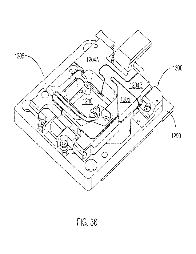
CA 03155946 2022-4-25
WO 2021/081432
PCT/1JS2020/057200
[00166] Figure 37 shows a perspective view of some embodiments of a split lid
containing a sensor,
with the split lid in an open position.
[00167] Figure 38 shows some embodiments of the un-assembled components of the
sensor that
can used with the split lid.
[00168] Figure 39 shows some embodiments of the assembled components of the
sensor that can
used with the split lid.
[00169] Figure 40 shows a side view of some embodiments of a split lid
containing a sensor, with
the split lid in a closed position.
[00170] Figure 41 shows a perspective view of some embodiments of an optical
switch that can be
used in the sensor.
[00171] Figures 42 and 43 show top views of some embodiments of the sensor in
actuated positions.
[00172] Figure 44 shows cell/bead distributions in the microfluidic devices in
some exemplary
embodiments.
DETAILED DESCRIPTION OF EXEMPLARY EMBODIMENTS
[00173] This specification describes exemplary embodiments and applications of
the disclosure.
The disclosure, however, is not limited to these exemplary embodiments and
applications or to
the manner in which the exemplary embodiments and applications operate or are
described
herein. Moreover, the figures may show simplified or partial views, and the
dimensions of
elements in the figures may be exaggerated or otherwise not in proportion. In
addition, as the
terms "on," "attached to," "connected to," "coupled to," or similar words are
used herein, one
element (e.g., a material, a layer, a substrate, etc.) can be "on," "attached
to," "connected to," or
"coupled to" another element regardless of whether the one element is directly
on, attached to,
connected to, or coupled to the other element or there are one or more
intervening elements
between the one element and the other element. Also, unless the context
dictates otherwise,
directions (e.g., above, below, top, bottom, side, up, down, under, over,
upper, lower, horizontal,
vertical, "x," "y," "z," etc.), if provided, are relative and provided solely
by way of example and
for ease of illustration and discussion and not by way of limitation. In
addition, where reference
is made to a list of elements (e.g., elements a, b, c), such reference is
intended to include any one
of the listed elements by itself, any combination of less than all of the
listed elements, and/or a
21
CA 03155946 2022-4-25
WO 2021/081432
PCT/1JS2020/057200
combination of all of the listed elements. Section divisions in the
specification are for ease of
review only and do not limit any combination of elements discussed.
[00174] As used herein, "substantially" means sufficient to work for the
intended purpose. The
term "substantially" thus allows for minor, insignificant variations from an
absolute or perfect
state, dimension, measurement, result, or the like such as would be expected
by a person of
ordinary skill in the field but that do not appreciably affect overall
performance. When used
with respect to numerical values or parameters or characteristics that can be
expressed as
numerical values, "substantially" means within ten percent.
[00175] The term "ones" means more than one. As used herein, the term
"plurality" can be 2, 3,
4, 5, 6, 7, 8, 9, 10, or more.
[00176] As used herein: pm means micrometer, gm3 means cubic micrometer, pL
means picoliter,
nL means nanoliter, and gL (or uL) means microliter.
[00177] As used herein, a "microfluidic device" or "microfluidic apparatus" is
a device that
includes one or more discrete microfluidic circuits configured to hold a
fluid, each microfluidic
circuit comprised of fluidically interconnected circuit elements, including
but not limited to
region(s), flow path(s), channel(s), chamber(s), and/or pen(s), and at least
one port configured to
allow the fluid (and, optionally, micro-objects suspended in the fluid) to
flow into and/or out of
the microfluidic device. Typically, a microfluidic circuit of a microfluidic
device will include a
flow region, which may include a microfluidic channel, and at least one
chamber, and will hold a
volume of fluid of less than about 1 mL, e.g., less than about 750, 500, 250,
200, 150, 100,75, 50,
25, 20, 15, 10, 9, 8, 7, 6, 5, 4, 3, or 2 pL. In certain embodiments, the
microfluidic circuit holds
about 1-2, 1-3, 1-4, 1-5, 2-5, 2-8, 2-10, 2-12, 2-15, 2-20, 5-20, 5-30, 5-40,
5-50, 10-50, 10-75, 10-
100, 20-100, 20-150, 20-200, 50-200, 50-250, or 50-300 L. The microfluidic
circuit may be
configured to have a first end fluidically connected with a first port (e.g.,
an inlet) in the
microfluidic device and a second end fluidically connected with a second port
(e.g., an outlet) in
the microfluidic device. In some embodiments a microfluidic device may have
more than two
ports, e.g. 3, 4, 5,6 or more ports; a typical example may have two inlets and
two outlets, e.g. for
fluidically connecting to two microfluidic circuits on the same microfluidic
device.
[00178] A microfluidic device may be referred to herein as a "microfluidic
chip" or a "chip".
[00179] A "microfluidic channel" or "flow channel" as used herein refers to
flow region of a
microfluidic device having a length that is significantly longer than both the
horizontal and vertical
22
CA 03155946 2022-4-25
WO 2021/081432
PCT/1JS2020/057200
dimensions. The length of the channel is generally defined by the flow path of
the channel. In the
case of a straight channel, the length would be the "longitudinal axis" of the
channel. The
"horizontal dimension" or "width" of the channel is the horizontal dimension
as observed in a
transverse section oriented perpendicular to the longitudinal axis of the
channel (or, if the channel
is curved, perpendicular to an axis tangential to the flow path of the channel
at the plane of the
transverse section). The "vertical dimension" or "height" of the channel is
the vertical dimension
as observed in a transverse section oriented perpendicular to the longitudinal
axis of the channel
(or, if the channel is curved, perpendicular to an axis tangential to the flow
path of the channel at
the plane of the transverse section).
[00180] The flow channel can be, for example, at least 5 times the length of
either the horizontal or
vertical dimension, e.g., at least 10 times the length, at least 25 times the
length, at least 100 times
the length, at least 200 times the length, at least 500 times the length, at
least 1,000 times the
length, at least 5,000 times the length, or longer. In some embodiments, the
length of a flow
channel is about 100,000 microns to about 500,000 microns, including any value
therebetween. In
some embodiments, the horizontal dimension is about 100 microns to about 1000
microns (e.g.,
about 150 to about 500 microns) and the vertical dimension is about 25 microns
to about 200
microns, (e.g., from about 40 to about 150 microns). It is noted that a flow
channel may have a
variety of different spatial configurations in a microfluidic device, and thus
is not restricted to a
perfectly linear element. For example, a flow channel may be, or include one
or more sections
having, the following configurations: curve, bend, spiral, incline, decline,
fork (e.g., multiple
different flow paths), and any combination thereof. In addition, a flow
channel may have different
cross-sectional areas along its path, widening and constricting to provide a
desired fluid flow
therein. The flow channel may include valves, and the valves may be of any
type known in the art
of microfluidics. Examples of microfluidic channels that include valves are
disclosed in U.S.
Patents 6,408,878 and 9,227,200, each of which is herein incorporated by
reference in its entirety.
[00181] The direction of fluid flow through the flow region (e.g., channel),
or other circuit element
(e.g., a chamber), dictates an "upstream" and a "downstream" orientation of
the flow region or
circuit element. Accordingly, an inlet will be located at an upstream
position, and an outlet will be
generally located at a downstream position. It will be appreciated by a person
of skill in the art,
that the designation of an "inlet" or an "outlet" may be changed by reversing
the flow within the
device or by opening one or more alternative aperture(s).
23
CA 03155946 2022-4-25
WO 2021/081432
PCT/1JS2020/057200
[00182] As used herein, "brightfield" illumination and/or image refers to
white light illumination
of the microfluidic field of view from a broad-spectrum light source, where
contrast is formed by
absorbance of light by objects in the field of view.
[00183] As used herein, "structured light" is projected light that is
modulated to provide one or
more illumination effects. A first illumination effect may be projected light
illuminating a portion
of a surface of a device without illuminating (or at least minimizing
illumination of) an adjacent
portion of the surface, e.g., a projected light pattern, as described more
fully below, used to activate
DEP forces within a DEP substrate. When using structured light patterns to
activate DEP forces,
the intensity, e.g., variation in duty cycle of a structured light modulator
such as a DMD, may be
used to change the optical power applied to the light activated DEP actuators,
and thus change
DEP force without changing the nominal voltage or frequency. Another
illumination effect that
may be produced by structured light includes projected light that may be
corrected for surface
irregularities and for irregularities associated with the light projection
itself, e.g., fall-off at the
edge of an illuminated field. Structured light is typically generated by a
structured light modulator,
such as a digital minor device (DMD), a microshutter array system (MSA), a
liquid crystal display
(LCD), or the like. Illumination of a small area of the surface, e.g., a
selected area of interest, with
structured light improves the signal-to-noise-ratio (SNR), as illumination of
only the selected area
of interest reduces stray/scattered light, thereby lowering the dark level of
the image. An important
aspect of structured light is that it may be changed quickly over time. A
light pattern from the
structured light modulator, e.g., DMD, may be used to autofocus on difficult
targets such as clean
minors or surfaces that are far out of focus. Using a clean minor, a number of
self-test features
may be replicated such as measurement of modulation transfer function and
field curvature/tilt,
without requiring a more expensive Shack-Hartmann sensor. In another use of
structured light
patterns, spatial power distribution may be measured at the sample surface
with a simple power
meter, in place of a camera. Structured light patterns may also be used as a
reference feature for
optical module/system component alignment as well used as a manual readout for
manual focus.
Another illumination effect made possible by use of structured light patterns
is selective curing,
e.g., solidification of hydrogels within the microfluidic device.
[00184] As used herein, the term "micro-object" refers generally to any
microscopic object that
may be isolated and/or manipulated in accordance with the present disclosure.
Non-limiting
examples of micro-objects include: inanimate micro-objects such as
microparticles; microbeads
24
CA 03155946 2022-4-25
WO 2021/081432
PCT/1JS2020/057200
(e.g., polystyrene beads, glass beads, amorphous solid substrates, LunilnexTM
beads, or the like);
magnetic beads; microrods; microwires; quantum dots, and the like; biological
micro-objects such
as cells; biological organelles; vesicles, or complexes; synthetic vesicles;
liposomes (e.g., synthetic
or derived from membrane preparations); lipid nanorafts, and the like; or a
combination of
inanimate micro-objects and biological micro-objects (e.g., microbeads
attached to cells,
liposome-coated micro-beads, liposome-coated magnetic beads, or the like).
Beads may include
moieties/molecules covalently or non-covalently attached, such as fluorescent
labels, proteins
(including receptor molecules), carbohydrates, antigens, small molecule
signaling moieties, or
other chemical/biological species capable of use in an assay. In some
variations, beads/solid
substrates including moieties/molecules may be capture beads, e.g., configured
to bind molecules
including small molecules, peptides, proteins or nucleic acids present in
proximity either
selectively or non-selectively. In one non-limiting example, a capture bead
may include a nucleic
acid sequence configured to bind nucleic acids having a specific nucleic acid
sequence or the
nucleic acid sequence of the capture bead may be configured to bind a set of
nucleic acids having
related nucleic acid sequences. Either type of binding may be understood to be
selective. Capture
beads containing moieties/molecules may bind non-selectively when binding of
structurally
different but physico-chemically similar molecules is performed, for example,
size exclusion beads
or zeolites configured to capture molecules of selected size or charge. Lipid
nanorafts have been
described, for example, in Ritchie et al. (2009) "Reconstitution of Membrane
Proteins in
Phospholipid Bilayer Nanodiscs," Methods Enzymol., 464:211-231.
[00185] As used herein, the term "cell" is used interchangeably with the term
"biological cell."
Non-limiting examples of biological cells include eukaryotic cells, plant
cells, animal cells, such
as mammalian cells, reptilian cells, avian cells, fish cells, or the like,
prokaryotic cells, bacterial
cells, fungal cells, protozoan cells, or the like, cells dissociated from a
tissue, such as muscle,
cartilage, fat, skin, liver, lung, neural tissue, and the like, immunological
cells, such as T cells, B
cells, natural killer cells, macrophages, and the like, embryos (e.g.,
zygotes), oocytes, ova, sperm
cells, hybridomas, cultured cells, cells from a cell line, cancer cells,
infected cells, transfected
and/or transformed cells, reporter cells, and the like. A mammalian cell can
be, for example, from
a human, a mouse, a rat, a horse, a goat, a sheep, a cow, a primate, or the
like.
[00186] A colony of biological cells is "clonal" if all of the living cells in
the colony that are capable
of reproducing are daughter cells derived from a single parent cell. In
certain embodiments, all
CA 03155946 2022-4-25
WO 2021/081432
PCT/1JS2020/057200
the daughter cells in a clonal colony are derived from the single parent cell
by no more than 10
divisions. In other embodiments, all the daughter cells in a clonal colony are
derived from the
single parent cell by no more than 14 divisions. In other embodiments, all the
daughter cells in a
clonal colony are derived from the single parent cell by no more than 17
divisions. In other
embodiments, all the daughter cells in a clonal colony are derived from the
single parent cell by
no more than 20 divisions. The term "clonal cells" refers to cells of the same
clonal colony.
[00187] As used herein in reference to a fluidic medium, "diffuse" and
"diffusion" refer to
thermodynamic movement of a component of the fluidic medium down a
concentration gradient.
[00188] The phrase "flow of a medium" means bulk movement of a fluidic medium
primarily due
to any mechanism other than diffusion, and may encompass perfusion. For
example, flow of a
medium can involve movement of the fluidic medium from one point to another
point due to a
pressure differential between the points. Such flow can include a continuous,
pulsed, periodic,
random, intermittent, or reciprocating flow of the liquid, or any combination
thereof. When one
fluidic medium flows into another fluidic medium, turbulence and mixing of the
media can result.
Flowing can comprise pulling solution through and out of the microfluidic
channel (e.g.,
aspirating) or pushing fluid into and through a microfluidic channel (e.g.
perfusing).
[00189] The phrase "substantially no flow" refers to a rate of flow of a
fluidic medium that, when
avenged over time, is less than the rate of diffusion of components of a
material (e.g., an analyte
of interest) into or within the fluidic medium. The rate of diffusion of
components of such a
material can depend on, for example, temperature, the size of the components,
and the strength of
interactions between the components and the fluidic medium.
[00190] As used herein in reference to different regions within a microfluidic
device, the phrase
"fluidically connected" means that, when the different regions are
substantially filled with fluid,
such as fluidic media, the fluid in each of the regions is connected so as to
form a single body of
fluid. This does not mean that the fluids (or fluidic media) in the different
regions are necessarily
identical in composition. Rather, the fluids in different fluidically
connected regions of a
microfluidic device can have different compositions (e.g., different
concentrations of solutes, such
as proteins, carbohydrates, ions, or other molecules) which are in flux as
solutes move down their
respective concentration gradients and/or fluids flow through the device.
[00191] As used herein, a "flow path" refers to one or more fluidically
connected circuit elements
(e.g. channel(s), region(s), chamber(s) and the like) that define, and are
subject to, the trajectory
26
CA 03155946 2022-4-25
WO 2021/081432
PCT/1JS2020/057200
of a flow of medium. A flow path is thus an example of a swept region of a
microfluidic device.
Other circuit elements (e.g., unswept regions) may be fluidically connected
with the circuit
elements that comprise the flow path without being subject to the flow of
medium in the flow path.
[00192] As used herein, "isolating a micro-object" confines a micro-object to
a defined area within
the microfluidic device. The defined area can be, for example, a chamber. As
used herein, a
"chamber" is a region within a microfluidic device (e.g., a circuit element)
that allows one or more
micro-object(s) to be isolated from other micro-objects located within the
microfluidic device.
Examples of chambers include microwells, which may be regions etched out of a
substrate (e.g., a
planar substrate), as described in U.S. Patent Application Publication Nos.
2013/0130232 (Weibel
et at) and 2013/0204076 (Han et al.), or a region formed in a multi-layer
device, such as the
microfluidic devices described in WO 2010/040851 (Dimov et at) or U.S. Patent
Application No.
2012/0009671 (Hansen et al.). Other examples of chambers include valved
chambers, such as
described in WO 2004/089810 (McBride et al.) and U.S. Patent Application
Publication No.
2012/0015347 (Singhal et al.). Still other examples of chambers include the
chambers described
in: Somaweera et al. (2013), "Generation of a Chemical Gradient Across an
Array of 256 Cell
Cultures in a Single Chip", Analyst., Vol. 138(19), pp 5566-5571; U.S. Patent
Application
Publication No. 2011/0053151 (Hansen et al.); and U.S. Patent Application
Publication No.
2006/0154361 (Wikswo et al.). Still other examples of chambers include the
sequestration pens
described herein. In certain embodiments, the chamber can be configured to
hold a volume of
fluid of about 100 pL to 1 nL, 100 pL to 2 nL, 100 pL to 5 nL, 250 pL to 2 nL,
250 pL to 5 nL,
250 pL to 10 nL, 500 pL to 5 nL, 500 pL to 10 nL, 500 pL to 15 nL, 750 pL to
10 nL, 750 pL to
15 nL, 750 pL to 20 nL, 1 to 10 nL, 1 to 15 nL, 1 to 20 nL, 1 to 25 nL, or 1
to 50 nL. mother
embodiments, the chamber can be configured to hold a volume of fluid of about
20 nL to 200nL,
100 to 200 nL, 100 to 300 nL, 100 to 400 nL, 100 to 500 nL, 200 to 300 nL, 200
to 400 nL, 200
to 500 nL, 200 to 600 nL, 200 to 700 nL, 250 to 400 nL, 250 to 500 nL, 250 to
600 nL, or 250 to
750 nL.
[00193] As used herein, "pen" or "penning" specifically refers to disposing
micro-objects within a
a sequestration pen within the microfluidic device. Forces used to pen a micro-
object may be any
suitable force as described herein such as dielectrophoresis (DEP), e.g., an
optically actuated
dielectrophoretic force (OEP); gravity; magnetic forces; locally actuated
fluid flow; or tilting. In
some embodiments, penning a plurality of micro-objects may reposition
substantially all the
27
CA 03155946 2022-4-25
WO 2021/081432
PCT/1JS2020/057200
micro-objects. In some other embodiments, a selected number of the plurality
of micro-objects
may be penned, and the remainder of the plurality may not be penned. In some
embodiments,
when selected micro-objects are penned, a DEP force, e.g., an optically
actuated DEP force or a
magnetic force may be used to reposition the selected micro-objects.
Typically, micro-objects
may be introduced to a flow region, e.g., a microfluidic channel, of the
microfluidic device and
thereafter introduced into a chamber by penning.
[00194] As used herein, "unpen" or "unpenning" refers to repositioning micro-
objects from within
a sequestration pen to a new location within a flow region, e.g., a
microfluidic channel, of the
microfluidic device. Forces used to unpen a micro-object may be any suitable
force as described
herein such as dielectrophoresis, e.g., an optically actuated dielectrophoretk
force; gravity;
magnetic forces; locally actuated fluid flow; or tilting. In some embodiments,
unpenning a
plurality of micro-objects may reposition substantially all the micro-objects.
In some other
embodiments, a selected number of the plurality of micro-objects may be
unpenned, and the
remainder of the plurality may not be unpenned. In some embodiments, when
selected micro-
objects are unpenned, a DEP force, e.g., an optically actuated DEP force or a
magnetic force may
be used to reposition the selected micro-objects.
[00195] As used herein, "export" or "exporting" can include, consist of, or
consist essentially of
repositioning micro-objects from a location within a microfluidic device,
e.g., a flow region, a
microfluidic channel, a chamber, etc., to a location outside of the
microfluidic device, such as a
well plate, a tube, or other receiving vessel. In some embodiments, exporting
a micro-object
comprises withdrawing (e.g., micro-pipetting) a volume of medium containing
the micro-object
from within the microfluidic device and depositing the volume of medium in or
upon the location
outside of the microfluidic device. In some related embodiments, withdrawing
the volume of
medium is preceded by disassembling the microfluidic device (e.g., removing an
upper layer, such
as a cover or lid, of the microfluidic device from a lower layer, such as a
base or substrate, of the
tnicrofluidic device) to facilitate access (e.g., of a micro-pipetted) to the
internal regions of the
tnicrofluidic device. In other embodiments, exporting a micro-object comprises
flowing a volume
of fluid containing the micro-object through the flow region (including, e.g.,
a microfluidic
channel) of the microfluidic device, out through an outlet of the microfluidic
device, and
depositing the volume of medium in or upon the location outside of the
microfluidic device. In
such embodiments, micro-object(s) within the microfluidic channel may be
exported without
28
CA 03155946 2022-4-25
WO 2021/081432
PCT/1JS2020/057200
requiring disassembly (e.g., removal of the cover of the device) or insertion
of a tool into an interior
region of the microfluidic device to remove micro-objects for further
processing. "Export" or
"exporting" may further comprise repositioning micro-objects from within a
chamber, which may
include a sequestration pen, to a new location within a flow region, such as a
microfluidic channel,
as described above with regard to "unpenning". A planar orientation of the
chamber(s) with
respect to the microfluidic channel, such that the chamber(s) opens laterally
from the microfluidic
channel, as described herein with regard to sequestration pens, permits easy
export of micro-
objects that have been positioned or repositioned (e.g., unpenned from a
chamber) to be disposed
within the microfluidic channel.
[00196] A mkrofluidic device can comprise "swept" regions and "unswept"
regions. As used
herein, a "swept" region is comprised of one or more fluidically
interconnected circuit elements
of a microfluidic circuit, each of which experiences a flow of medium when
fluid is flowing
through the microfluidic circuit. The circuit elements of a swept region can
include, for example,
regions, channels, and all or parts of chambers. As used herein, an "unswept"
region is comprised
of one or more fluidically interconnected circuit element of a microfluidic
circuit, each of which
experiences substantially no flux of fluid when fluid is flowing through the
microfluidic circuit.
An unswept region can be fluidically connected to a swept region, provided the
fluidic connections
are structured to enable diffusion but substantially no flow of media between
the swept region and
the unswept region. The microfluidic device can thus be structured to
substantially isolate an
unswept region from a flow of medium in a swept region, while enabling
substantially only
diffusive fluidic communication between the swept region and the unswept
region. For example,
a flow channel of a micro-fluidic device is an example of a swept region while
an isolation region
(described in further detail below) of a microfluidic device is an example of
an unswept region.
[00197] As used herein, a "non-sweeping" rate of fluidic medium flow means a
rate of flow
sufficient to permit components of a second fluidic medium in an isolation
region of the
sequestration pen to diffuse into the first fluidic medium in the flow region
and/or components of
the first fluidic medium to diffuse into the second fluidic medium in the
isolation region; and
further wherein the first medium does not substantially flow into the
isolation region.
[00198] In some embodiments, the systems can include a support (also known as
a "nest")
configured to hold a microfluidic device. The support can include, for
example, a socket
configured to interface with and/or hold an optically actuated microfluidic
device, a printed circuit
29
CA 03155946 2022-4-25
WO 2021/081432
PCT/1JS2020/057200
board assembly (PCBA), an electrical signal generation subsystem, a thermal
control subsystem,
or any combination thereof.
[00199] In certain embodiments, the support includes a socket capable of
interfacing with a
microfluidic device, such as an optically actuated microfluidic device. An
exemplary socket 106
is included in the support 100 of Figures IA and 1B. However, the shape and
functionality of the
socket 106 need not be exactly as shown in Figures lA and 1B. For example, the
socket can
include a lid). Moreover, the socket 106 can be adjusted as needed to match
the size and type of
microfluidic device 110 with which the socket 106 is intended to interface. A
variety of
microfluidic devices 110 are known in the art, including devices 110 having
optically actuated
configurations, such as an optoelectronic tweezer (OET) configuration and/or
an opto-
electrowetting (OEW) configuration. Examples of suitable OET configurations
are illustrated in
the following U.S. patent documents, each of which is incorporated herein by
reference in its
entirety, as though set forth in full: U.S. Patent No. RE44,711 (Wu et al.)
(originally issued as U.S.
Patent No. 7,612,355); and U.S. Patent No. 7,956,339 (Ohta et al.). Examples
of OEW
configurations are illustrated in US Patent No. 6,958,132 (Chiou et al.) and
US Patent Application
Publication No. 2012/0024708 (Chien et al.), both of which are incorporated by
reference herein
in their entirety, as though set forth in full. Yet another example of
optically actuated microfluidic
device includes a combined OET/OEW configuration, examples of which are shown
in U.S. Patent
Publication Nos. 20150306598 (Khandros et al.) and 20150306599 (Ithandros et
al.) and their
corresponding PCT Publications W02015/164846 and W02015/164847, all of which
are
incorporated herein by reference in their entirety, as though set forth in
full.
[00200] The support 100 depicted in Figures 1A and 1B also includes a base 102
and a cover 104
(omitted in Figure 1B). The support 100 also includes a plurality of
connectors: a first fluidic
input/output 112; a communications connection 114; a power connection 116; and
a second fluidic
input/output 118. The first and second fluidic input/outputs 112, 118 are
configured to deliver a
cooling fluid to and from a cooling block (shown in Figure 3) used to cool the
microfluidic device
110. Whether the first and second fluidic input/outputs 112, 118 are input or
outputs depends on
the direction of fluid flow through the support 100. The first and second
fluidic input/outputs 112,
118 are fluidly coupled to the cooling block by first and second fluidic
connectors 142, 144
disposed in the support 100. The communications connection 114 is configured
to connect the
support 110 with other components of the system for operating microfluidic
devices, as described
CA 03155946 2022-4-25
WO 2021/081432
PCT/1JS2020/057200
below. The power connection 116 is configured to provide power (e.g.,
electricity) to the support
110.
[00201] In certain embodiments, the support 100 can include an integrated
electrical generation
subsystem 138. The electrical generation subsystem 138 can be configured to
apply a biasing
voltage across a pair of electrodes in a microfluidic device 110 that is being
held by the support
100. The ability to apply such a biasing voltage does not mean that a biasing
voltage will be
applied at all times when the microfluidic device 110 is held by the support
100. Rather, in most
cases, the biasing voltage will be applied intermittently, e.g., only as
needed to facilitate the
generation of microfluidic forces, such as dielectrophoresis or electro-
wetting, or the measurement
of complex impedance in the microfluidic device 110.
[00202] Typically, the electrical signal generation subsystem 138 will include
a waveform
generator 202, as shown in Figure 2. The electrical generation subsystem 138
can further include
a sensing module 208 (e.g., an oscilloscope) and/or a waveform amplification
circuit 204
configured to amplify a waveform received from the waveform generator 202. The
sensing
module 208, if present, can be configured to measure the waveform supplied to
the microfluidic
device 110 held by the support 100. In certain embodiments, the sensing module
208 measures
the waveform at a location proximal to the microfluidic device 110 (and distal
to the waveform
generator 202), thus ensuring greater accuracy in measuring the waveform
actually applied to the
microfluidic device 110. Data obtained from the sensing module 208 measurement
can be, for
example, provided as feedback to the waveform generator 202, and the waveform
generator 202
can be configured to adjust its output based on such feedback. An example of a
suitable combined
waveform generator 202 and sensing module 208 is the RED PITAYATm.
[00203] In certain embodiments, the support 100 can include a thermal control
subsystem 140. The
thermal control subsystem 140 can be configured to regulate the temperature of
a microfluidic
device 110 held by the support 100. As shown in Figure 3, the thermal control
subsystem 140 can
include a Peltier thermoelectric device 304 and a proximal component of a
cooling unit 312. The
Peltier thermoelectric device 304 can have a first surface 306 configured to
interface with at least
one surface of the microfluidic device 110. The cooling unit can include, for
example, a cooling
block 322. A second surface 308 of the Peltier thermoelectric device 304
(e.g., a surface 308
opposite the first surface 306) can be configured to interface with a surface
of such a cooling block
322. All or part of the cooling block 322 (e.g., a part that interfaces with
the Peltier thermoelectric
31
CA 03155946 2022-4-25
WO 2021/081432
PCT/1JS2020/057200
device 304) can be made from a material having a high thermal conductivity.
For example, the
material can be a metal, such as aluminum. The cooling block 322 can be
connected to a fluidic
path 324 configured to circulate cooled fluid between a fluidic cooling device
326 and the cooling
block 322. The fluidic path 324 can include the fluidic input/outputs 112, 118
and the fluidic
connectors 142, 144 described in connection with Figure 1. The Peltier
thermoelectric device 304
and the cooling block 322 can be mounted on the support 100.
[00204] The thermal control subsystem 140 can further include a thermoelectric
power module 302,
as shown in Figure 3. The thermoelectric power module 302 can regulate the
temperature of the
Peltier thermoelectric device 304 so as to achieve a target temperature for
the microfluidic device
110. Feedback for the thermoelectric power module 302 can include a
temperature value provided
by an analog circuit 400, such as shown in Figure 4. Alternatively, the
feedback can be provided
by a digital circuit (not shown). The Peltier thermoelectric device 304, the
cooling block 322, and
the thermoelectric power module 302 all can be mounted on the support 100.
[00205] In certain embodiments, the support 100 can also include or interface
with an
environmental temperature monitor/regulator in addition to the thermal control
subsystem 140.
[00206] The analog circuit 400 depicted in Figure 4 includes a resistor 402, a
thermistor 406, and
an analog input 404_ The analog input is operatively coupled to the electrical
signal generation
subsystem 138 (e.g., the sensing module 208 thereof) and provides a signal
thereto that can be
used to calculate the temperature of the microfluidic device 110. The
thermistor 406 is configured
such that its resistance may decrease in a known manner when the temperature
of the thermistor
406 decreases and increase in a known manner when the temperature of the
thermistor 406
increases. The analog circuit 400 is connected to a power source (not shown)
which is configured
to deliver a biasing voltage to electrode 408. In one particular embodiment,
the resistor 402 can
have a resistance of about 10,000 ohms, the thermistor 406 can have a
resistance of about 10,000
ohms at 25 C, and the power source (e.g., a DC power source) can supply a
biasing voltage of
about 5 V. The analog circuit 400 is exemplary, and other systems can be used
to provide a
temperature value for feedback for the thermoelectric power module 302_
[00207] In certain embodiments, the support 100 further comprises a controller
136 (e.g., a
microprocessor). The controller 136 can be used to sense and/or control the
electrical signal
generation subsystem 138. In addition, to the extent that the support 100
includes a thermal control
subsystem 140, the controller 136 can be used to sense and/or control the
thermal control
32
CA 03155946 2022-4-25
WO 2021/081432
PCT/1JS2020/057200
subsystem 140. Examples of suitable controllers 136 include the ARDUINOTM
microprocessors,
such as the ARDUINO NANOTM. The controller 136 can be configured to interface
with an
external controller (not shown), such as a computer or other computational
device, via a
plug/connector 134. In certain embodiments, the external controller can
include a graphical user
interface (GUI) configured to sense and/or control the electrical signal
generation subsystem 138,
the thermal control subsystem 140, or both. An exemplary GUI 500, which is
configured to control
both the electrical signal generation subsystem 138 and the thermal control
subsystem 140, is
depicted in Figure 5.
[00208] In certain embodiments, the support 100 can include a printed circuit
board (PCB) 132.
The electrical signal generation subsystem 138 can be mounted on and
electrically integrated into
the PCB 132. Similarly, to the extent that the support 100 includes a
controller 136 or a thermal
control subsystem 140, the controller 136 and/or the thermoelectric power
module 302 can be
mounted on and electrically integrated into the PCB 132.
[00209] Thus, as shown in Figures lA and 1B, an exemplary support 100 can
include a socket 106,
an interface 134, a controller 136, an electrical generation subsystem 138,
and a thermal control
subsystem 140, all of which are mounted on and electrically integrated into
PCB 132, thereby
forming a printed circuit board assembly (PCBA) 130. As discussed above, the
socket 106 can be
designed to hold a microfluidic device 110 (or "consumable"), including an
optically actuated
microfluidic device.
[00210] In certain specific embodiments, the electrical generation subsystem
138 can include a
RED PITAYATm waveform generator 202/sensing module 208 and a waveform
amplification
circuit 204 that amplifies the waveform generated by the RED PITAYATm waveform
generator
202 and passes the amplified waveform (voltage) 206 to the microfluidic device
110. Both the
RED PITAYATm unit 202, 208 and the waveform amplification circuit 204 can be
electrically
integrated into the PCB 132 as an electrical generation subsystem 138, as
shown in Figure 1B.
Moreover, the RED PITAYATm unit 202,208 can be configured to measure the
amplified voltage
at the microfluidic device 110 and then adjust its own output voltage as
needed such that the
measured voltage at the microfluidic device 110 is the desired value. The
amplification circuit
204 can have, for example, a +6.5V to -6.5V power supply generated by a pair
of DC-DC
converters mounted on the PCB 132, resulting in a signal of up to 13 Vpp at
the microfluidic device
110.
33
CA 03155946 2022-4-25
WO 2021/081432
PCT/1JS2020/057200
[00211] In certain specific embodiments, the support 100 includes a thermal
control subsystem 140
(shown in Figure 3) having a Peltier thermoelectric device 304, located
between a liquid-cooled
aluminum block 322 and the back side of the microfluidic device 110, a
POLOLUTM
thermoelectric power supply (not shown), and an ARDUINO NANOTM controller 136.
Feedback
for the thermal control subsystem 140 can be an analog voltage divider circuit
400 (shown in
Figure 4) which includes a resistor 402 (e.g. resistance 10kOhm+/-0.1%,
temperature coefficient
+1-0.02 ppm/C ) and a negative temperature coefficient thermistor 406 (nominal
resistance
10kOhm+/-0.01%). The controller 136 can measure the voltage from the feedback
circuit 400 and
then use the calculated temperature value as input (e.g., to an on-board PIT)
control loop algorithm)
to drive both a directional and a pulse-width-modulated signal pin on the
thermoelectric power
module 302, and thereby actuate the thermoelectric subsystem 140. A liquid
cooling unit 326 can
be configured to pump fluid through the cooling path 324 located, in part, in
the support 100 (e.g.,
fluidic input/outputs 112, 118 and the fluidic connectors 142, 144) and, in
part, at the periphery of
the support 100.
[00212] In certain specific embodiments, the support 100 includes a serial
port 114 and a Plink tool
that together allow the RED PITAYATm unit to communicate with an external
computer. The
serial port 114 can also allow the controller 136 to communicate with the
external computer.
Alternatively, a separate serial port (not shown) can be used to allow the
controller 136 to
communicate with the external computer. In other embodiments, the support 100
can include a
wireless communication device configured to facilitate wireless communication
between
components of the support 100 (e.g., the controller 136 and/or the electrical
generation subsystem
138) and the external computer, which can include a portable computing device
such as a cell
phone, a PDA, or other handheld device. A GUI (e.g., such as shown in Figure
5) on the external
computer can be configured for various functions, including, but not limited
to, plotting
temperature and waveform data, performing scaling calculations for output
voltage adjustment,
and updating the controller 136 and RED PITAYATm device 202, 208.
[00213] In certain embodiments, the support 100 can also include or interface
with an
inductance/capacitance/resistance (LCR) meter configured to measure
characteristics of the
contents (e.g., fluidic contents) of the microfluidic device 110.
[00214] For example, the LCR meter can be configured to measure the complex
impedance of a
system, particularly the complex impedance of a fluid as it enters, is located
within, and/or as it
34
CA 03155946 2022-4-25
WO 2021/081432
PCT/1JS2020/057200
exits an microfluidic device 110. In some embodiments, the LCR meter can be
connected to and/or
integrated into a fluid line that carries fluid into or out of the
microfluidic device 110. In other
embodiments, the LCR meter can be connected to or an integral part of the
electrical generation
subsystem 138. Thus, in certain specific embodiments, the RED PITAYATm
waveform generator
202 and sensing module 208 in the support 100 can be configured to function as
an LCR meter.
In certain embodiments, electrodes of the microfluidic device 110 which are
configured for use
with the electrical generation subsystem 138 can also be configured for use
with the LCR meter.
Measuring the impedance of a system can determine various system
characteristics and changes
therein, such as the height of the fluidic circuit within the microfluidic
device 110, changes in the
salt content of fluid in the microfluidic device 110 (which may correlate with
the status of
biological micro-objects therein), and the movement of specific volumes of
fluids (having different
impedances) through the microfluidic device 110.
[00215] In certain embodiments, measuring the impedance of a system can be
used to accurately
(i.e., close to the true value) and precisely (i.e., repeatably) detect a
change from a first fluid in a
system (i.e., the microfluidic device 110) to a second fluid in the system.
For example, the first
fluid could be deionized water (DI) and the second fluid could be a saline
solution (e.g., phosphate-
buffered saline or "PBS"), or vice versa. Alternatively, the first fluid could
be a saline solution
(e.g., PBS) and the second fluid could be a cell culture medium having an
impedance that is
delectably different than the saline solution, or vice versa. In still other
alternatives, the first fluid
could be a first cell culture medium and the second fluid could be a second
cell culture medium
having an impedance that is detectably different than the first cell culture
medium. Figure 9 is a
diagram depicting an impedance measurement circuit 900 for detecting the
impedance of a system.
The circuit 900 includes an output 902 from the waveform generator 202 of the
electrical
generation subsystem 138, and two inputs 904, 906 to the sensing module 208 of
the electrical
generation subsystem 138. The circuit 900 also includes the microfluidic
device 110 (connected
via the socket 106 of the support 100) and a shunt resistor 908. The shunt
resistor 908 can be
selected so as to render the LCR sufficiently accurate to measure impedances
in the 0 to about
5,000 ohm range (e.g., 0 to about 4,000,0 to about 3,000,0 to about 2,500, 0
to about 2,000,0 to
about 1,500, or 0 to about 1,000 ohm range). The microfluidic device 110
functions in the circuit
900 as a measurement cell, with the base (e.g., a semi-conductor device) and
cover (e.g., having
an indium tin oxide (ITO) layer) of the microfluidic device 110 functioning as
electrodes. In
CA 03155946 2022-4-25
WO 2021/081432
PCT/1JS2020/057200
certain specific embodiments, the output 902 of circuit 900 can come from the
waveform generator
202 of a RED PITAYATm device and the inputs 904, 906 can originate from the
microfluidic
device 110 and be received by the sensing module 208 of the RED PITAYATm
device. In certain
specific embodiments, the shunt resistor 908 can be a 50 ohm resistor. In
these embodiments, the
electrical generation subsystem 138 may be switched between an "optical
actuation mode" and an
"LCR mode." Moreover, when in LCR mode, the electrical generation subsystem
138 can be
connected to a computer running a MATLAB script.
11002161 The system of the systems thus provides methods for determining the
flow volume (Va.)
of a microfluidic device 110. For example, the microfluidic device 110 is
initially filled with a
first fluid associated with a first impedance (e.g., DI, which is associated
with an impedance of
about 450 ohms). Then, a second fluid associated with a second impedance that
is detectably
different than the first impedance (e.g., PBS, which is associated with an
impedance of about 160
ohms) is flowed into and through the microfluidic device 110. The second fluid
can be flowed
into the microfluidic device 110, for example, through a port capable of
functioning as either a
fluid inlet port or a fluid outlet port. The system continuously measures the
complex impedance
of the microfluidic device 110 as the second fluid is flowing into and through
the microfluidic
device 110. As discussed above, to measure the complex impedance of the
microfluidic device
110 at a particular time point, the system applies a voltage potential to the
microfluidic device 110
and, concomitantly, receives signals from the microfluidic device 110 that are
used to calculate
the complex impedance. The voltage potential applied to the microfluidic
device can have a
frequency of about 10 kHz to about 1 MHz (e.g., about 50 kHz to about 800 kHz,
about 100 kHz
to about 700 kHz, about 200 kHz to about 600 kHz, about 300 kHz to about 500
kHz, about 350
kHz to about 400 kHz, or about 380 kHz). The specific frequency can be
selected based on
properties of the microfluidic device 110 and the first and second fluids so
as to optimize accuracy
of the impedance measurement, minimize measurement time, and reduce inductive
effects. The
second fluid is flowed into and through the microfluidic device 110 until the
measured complex
impedance changes from the first impedance associated with the first fluid to
the second impedance
associated with the second fluid. The minimum amount of second fluid required
to completely
switch the complex impedance of the microfluidic device 110 from the first
impedance to the
second impedance is a measure of the flow volume (Viow) of the microfluidic
device. Starting
from the point when the system begins to pump the second fluid to the
microfluidic device 110,
36
CA 03155946 2022-4-25
WO 2021/081432
PCT/1JS2020/057200
the volume of the second fluid required to switch the complex impedance of the
microfluidic
device 110 from the first impedance to the second impedance can include (1)
the flow volume
(Vflow) of the microfluidic device 110, (2) the volume of the fluid outlet
port of the microfluidic
device, and (3) the flow volume of the tubing carrying the second fluid from a
pump to the
microfluidic device 110. Because the flow of the second fluid through the
tubing and fluid outlet
port does not change the complex impedance of the microfluidic device 110, the
flow volume of
the tubing and inlet port can be readily distinguished from the flow volume of
the microfluidic
device 110.
[00217] Using the calculated flow volume of a microfluidic device 110, the
system further provides
methods for reliably exporting one or more micro-objects from the microfluidic
device 110 in a
discrete volume of fluid. Having determined the flow volume (Vflow) of the
microfluidic device
110, the minimal export volume (Vex) needed to export a micro-object (e.g., a
biological cell)
positioned within the flow path can be approximated by calculating the portion
of the flow path
that separates the micro-object from the fluid outlet port of the microfluidic
device 110. For
example, a total length (14.0 of the flow path can be determined by tracing
the flow path of the
microfluidic device 110 from the fluid inlet port to the fluid outlet port.
The export length (Lex) of
the flow path can be determined by tracing the flow path of the microfluidic
device 110 from the
location of the micro-object in the flow path to the fluid output port. The
minimal amount of fluid
(Vex) needed to export the micro-object from the microfluidic device 110 can
thus be calculated
as: Vex = (Lx/Lt) * Vflow- Alternatively, the total volume of the flow path
(Vflow_tot) can be
estimated from the predicted geometry of the flow path (e.g., using CAD
drawings); and the total
volume of the export flow path (Vex) can likewise be calculated from the
predicted geometry of
the flow path. In such an embodiment, minimal amount of fluid (Vex) need to
export the micro-
object from the microfluidic device 110 can be calculated as: Vex = (Vex-
tot/Vflow-tot) * Vflow.
Regardless of the approach to calculating Vex, the micro-object can be
exported from the
microfluidic device 110 by flowing a volume of fluid through the fluid outlet
port of the
microfluidic device 110 that is at least as large as Vex. To ensure reliable
export, the micro-object
can be exported from the microfluidic device 110 by flowing a volume of fluid
(Vex_ret) that is
equal to C * Vex, wherein C is a scaling factor that is equal to about 1.1 or
greater (e.g., about 1.2,
1.3, 1.4, 1.5, 1.6, 1.7, 1.8, 1.9, 2.0, or greater). In some methods, a
leading portion of Vex (or Vex-
re0 is discarded before a residual volume (Vres, equal to Vex (or Vex-rel)
minus the leading portion)
37
CA 03155946 2022-4-25
WO 2021/081432
PCT/1JS2020/057200
that contains the micro-object(s) is exported from the microfluidic device
110. For example, Vt.
(or Vex_rei) could equal 1.0 L and a leading volume of 0.5 ILL could be
discarded, resulting in the
micro-object(s) being exported in a final volume Vies of 0.5 L. In this
manner, the micro-object(s)
can be exported in a small but discrete volume of fluid. Depending on how the
method is
performed, Vex, Vex-rel, Or Vres can be about 2.0 gL, 1.5 gL, 1.2 gL, 1.0 gL,
0.9 pt, 0_8 gL, 0.7 gL,
0.6 gL, 0.5 gL, 0.4 gL, 03 gL, 0.25 gL, or less. Typically, the volume of
fluid containing the
micro-object(s) (i-e-, Vex, Vex-ml, Or Vies) is exported through export tubing
having a finite internal
volume before reaching a collection receptacle. Accordingly, the calculations
used in the methods
can be adjusted to account for the known or estimated volume of the export
tubing. For example,
the export tubing could have an internal volume of 5.0 L. In such a case, a
Vex (or Vex_m) of 1.0
gL would be adjusted to 6_0 gL, and a discarded leading volume of 0.5 !IL
would be adjusted to
5.5 gL, thus resulting in a Vres of 0.5 L remaining the same.
[00218] In certain embodiments, the support 100 includes one or more valves
coupled to the support
100, the one or more valves being configured to limit (e.g., stop) movement of
fluid within a
microfluidic device 110 coupled to the support 100. Although fluid flow into
and out of the
microfluidic device 110 can be controlled, for example, via a pump, the
movement of fluid lines
connecting the pump to the microfluidic device 110 can create undesirable
movement (e.g., drift
and/or oscillation) of fluid within the microfluidic device 110 even when the
pump is off. This
movement, in turn, can disrupt processes taking place within the microfluidic
device 110, such as
detection and/or selection of micro-objects (e.g., for counting,
characterization, and/or movement
between channels and chambers) or assays being performed within the
microfluidic device 110.
One or more valves located in the support 100 can diminish or prevent such
undesirable movement
of fluid within the rnicrofluidic device 110. Suitable valves can
substantially lack internal dead
space (i.e., space within the valve that is accessible to fluid but
experiences very little fluid flux
when fluid is flowing through the valve). In certain embodiments, at least one
of the one or more
valves is a thermally controlled flow controller, such as a freeze valve.
Figures 10 and 11 depict
a thermally controlled flow controller 1040 for use with a support 100
according to one
embodiment of the systems. The flow controller 1000 includes a temperature
regulation device
1004, a thermally conductive interface 1006, and a flow segment (hidden) of a
fluid line 1008.
The temperature regulation device 1004 can include one or more Peltier
thermoelectric devices
38
CA 03155946 2022-4-25
WO 2021/081432
PCT/1JS2020/057200
(e.g., a stack of two, three, four, five, or more Peltier devices). The
thermally conductive interface
1006 may be made from a material having high thermal conductivity that is
resistant to thermal
damage, such as a metal (e.g., copper). The thermally conductive interface
1006 can wrap around
the flow segment of the fluid line 1008. The thermally conductive interface
1006 can be, for
example, a sleeve or other object that completely surrounds the flow segment
of the fluid line
1008, or it can have a grooved surface that accommodates the flow segment of
the fluid line 1008
within its groove. The fluid in the fluid line 1008 may be a liquid that
freezes solid at a temperature
achievable by the flow controller 1000. The thermally conductive interface
1006 is disposed
adjacent the temperature regulation device 1004, preferably in contact with a
thermally conductive
surface thereof to increase the efficiency of the flow controller 1000.
[00219] In certain embodiments, the thermally controlled flow controller 1000
can include a heat
sink 1002, which may be made of one or more materials having a high thermal
conductivity (and
low thermal capacitance), such as aluminum. Alternatively, the flow controller
1000 can be
configured to rest on and/or be secured to a heat sink 1002. In addition, the
flow controller 1000
can include insulating material 1010, which may be configured to prevent
moisture from
interfering with the function of the flow controller 1000, which can happen
when moisture
condenses on the thermally conductive interface 1006 and/or temperature
regulation device 1004.
The flow controller 1000 can also include a cover 1012. The cover 1012, or
another device (e.g.,
a clamp), can be configured to hold the thermally conductive interface 1006
against the
temperature regulation device 1004 and, e.g., thereby increase the efficiency
of the flow controller
1000.
[00220] Figure 12 depicts a socket 106 and a pair of valves, each a thermally
controlled flow
controller 1000, according to another embodiment. The flow controllers 1000
are disposed directly
upstream and downstream of the socket 106. As shown in Figure 12, each flow
controller 1000
includes a heat sink 1002, and an enclosure 1014. Each enclosure 1014 contains
a temperature
regulation device 1004, a thermally conductive interface 1006, and a flow
segment of a fluid line
1008. The fluid lines 1008 can be seen exiting from the flow controllers 1000
and entering the
socket 106. The enclosures 1014 may be made from a material having a low
thermal conductivity
and/or a low gas permeability. The material can be, for example, a polymer,
such as PVC or the
like. The enclosures 1014 may each have a volume of at least twice (e.g., 2 to
10 times, 2 to 7
times, 2 to 5 times, 2 to 4 times, or 2 to 3 times) the volume of the
respective temperature regulation
39
CA 03155946 2022-4-25
WO 2021/081432
PCT/1JS2020/057200
devices 1004 contained therein. The enclosures can be configured to prevent
moisture from
interfering with the function of the flow controllers 1000, which can happen
when moisture
condenses on the respective temperature regulation devices 1004 and/or
thermally conductive
interfaces 1006. Figure 12 also depicts a secondary heat sink 1020 upon which
the flow controllers
1000 may be mounted. The secondary heat sink 1020 is configured to absorb heat
from the heat
sinks 1002 of the flow controllers 1000.
[00221] Figure 13 depicts the heat sink 1002 and enclosure 1014 of a thermally
controlled flow
controller 1000 like the ones depicted in Figure 12. The underside of the
enclosure 1014 is visible
in Figure 13, showing grooves 1016 configured to accommodate the fluid line
1008 (not shown)
and/or at least part of the thermally conductive interface 1006. The grooves
1016 can be further
configured to hold the thermally conductive interface 1006 (not shown) against
the temperature
regulation device 1004 (e.g., one or more (e.g., a stack of) Peltier
thermoelectric devices; not
shown).
[00222] Figure 14 depicts the exterior of a thermally controlled flow
controller 1000 according to
still another embodiment. As shown, the flow controller 1000 includes a cover
1030, a bottom
portion 1040, and a heat sink 1002. The cover 1030 defines respective
pluralities of indicator
openings 1034, 1036 configured to allow indicators (e.g., LEDs) to be observed
from a position
external to the cover 1030. The indicators can be configured to indicate
whether the flow controller
1000 is on or off and/or whether the flow segment of the fluid line 1008 is in
an open (i.e., not
frozen) or closed (i.e., frozen) configuration. In addition, the cover 1030
can define fastener
openings 1032 configured to admit fasteners (e.g., screws) for assembly of the
flow controller
1000. The bottom portion 1040 defines a plurality of fluid line openings 1042
configured to admit
fluid lines (not shown) into the interior of the bottom portion 1040.
[00223] Figures 15 and 16 depict the top and the bottom, respectively, of the
cover 1030 depicted
in Figure 14, shown without the bottom portion 1040. The indicator openings
1034, 1036 and the
fastener openings 1032 are also depicted in Figures 15 and 16. Figure 16 also
depicts a cavity
1038 formed in the underside of the cover 1030, which is configured to hold a
PCB (not shown)
of the thermally controlled flow controller 1000. The PCB can include
circuitry configured to
control one or more temperature regulation devices 1004 (not shown) and/or one
or more
indicators (not shown). The cover 1030 can be made from a low thermal
conductivity material,
such as a polymer (e.g., PVC).
CA 03155946 2022-4-25
WO 2021/081432
PCT/1JS2020/057200
[00224] Figure 17 depicts the bottom portion 1040 and the heat sink 1002 of
the thermally
controlled flow controller 1000 depicted in Figure 14, shown without the cover
1030. The bottom
portion 1040 includes a sleeve 1050 and an enclosure 1044 configured to hold
the sleeve 1050.
The bottom portion 1040 also defines fastener openings 1048 configured to
admit fasteners (e.g.,
screws) for mounting the cover 1030 and the bottom portion 1040 on the heat
sink 1002. In
addition to holding the sleeve 1050, the enclosure 1044 also defines a
plurality of fluid line
openings 1042 (shown in Figure 18), which correspond to a plurality of fluid
line openings 1052
in the sleeve 1050 (as shown in Figure 21). The fluid line openings 1042 pass
completely through
the enclosure 1044 in the horizontal plane of the enclosure 1044. Figure 18 is
a perspective view
of the enclosure 1044 from below. The angle of the perspective view shows two
corresponding
sets of fluid line openings 1042 and two cavities 1046 formed in the underside
of the enclosure
1044. The cavities 1046 in the enclosure 1044 are each configured to hold
temperature regulation
devices 1004 (e.g., each having one or more (e.g., a stack of two or more)
Peltier thermoelectric
devices; not shown) and wiring associated therewith (not shown).
[00225] Figure 19 depicts the heat sink 1002, which optionally defines two
cavities 1060, each
configured to hold a temperature regulation device 1004 (e.g., having one or
more (e.g., a stack of
two or more) Peltier thermoelectric devices). The heat sink 1002 is optionally
configured to be
coupled to a secondary heat sink 1020 or a support 100, which may function as
a secondary heat
sink.
[00226] Figures 20 and 21 depict a sleeve 1050 configured to hold two fluid
lines 1008 (e.g., an
inlet and an outlet; not shown). The sleeve 1050 may be configured to
completely enclose the
flow segments of the fluid lines 1008. Alternatively, the sleeve 1050 can have
grooves configured
to accommodate the flow segments of the fluid lines 1008. Thus, the sleeve
1050 is an embodiment
of a thermally conductive interface 1006. Accordingly, the sleeve 1050
facilitates maintaining the
flow segments of the fluid lines 1008 in proximity to the temperature
regulation device 1004 (not
shown). The sleeve 1050 may be made of a high thermal conductivity (and low
thermal
capacitance) material, such as a metal (e.g., copper). The side view in Figure
21 shows the fluid
line 1008 openings 1052 defined by the sleeve 1050. As shown, the fluid line
openings 1052 pass
completely through the sleeve 1050 in the horizontal plane of the sleeve 1050.
The fluid line
openings 1052 are substantially aligned with corresponding fluid line openings
1042 in the
enclosure 1044 (as shown in Figure 18), such that, when the sleeve 1050 is
disposed in the
41
CA 03155946 2022-4-25
WO 2021/081432
PCT/1JS2020/057200
enclosure 1044 (as shown in Figure 17), the fluid lines 1008 can pass through
both the enclosure
1044 and the sleeve 1050. Further, when the sleeve 1050 is disposed in the
enclosure 1044 (as
shown in Figure 17), the sleeve 1044 is placed into contact with the tops of
both temperature
regulation devices 1004 (e.g., each which can include one or more (e.g., a
stack of two or more)
Peltier thermoelectric devices; not shown).
[00227] In certain embodiments, the thermally controlled flow controller 1000
also includes a
thermistor (not shown). The thermistor is configured to monitor the
temperature of the sleeve
and/or the temperature regulation device 1004 (or a surface thereof). The
monitored temperature
can provide feedback to indicate the open or closed condition of the flow
controller 1000.
[00228] In certain embodiments, the thermally controlled flow controller 1000
also includes or is
operatively coupled to a printed circuit board (PCB; not shown), as discussed
above. The PCB
can be configured to interface with the thermistor. The PCB may also be
configured to regulate
the current (e.g., DC) delivered to the temperature regulation devices 1004.
Further, the PCB may
be configured to step down the current delivered to the temperature regulation
devices 1004.
[00229] The thermally controlled flow controllers 1000 described above are
robust and have
substantially eliminated dead spaces (compare to other fluid valves) in which
bacteria or other
debris can accumulate and/or grow. Further, the flow controllers 1000 reduce
microbial
contamination associated with other types of valves. Moreover, the flow
controllers 1000 limit
movement of fluid within a microfluidic device (e.g., a microfluidic device
110) connected thereto,
which would otherwise result from flexing of fluid lines connected to the
inlets and outlets of the
microfluidic device. To optimize the system for minimizing fluid movement
within rnicrofluidic
devices, the flow controller(s) 1000 should be disposed as close to the inlet
and outlets of the
microfluidic devices as practical.
[00230] The thermally controlled flow controllers 1000 unfortunately have
several limitations. In
some configurations, they can take a long time to cool to the desired
temperature and freeze the
fluid lines, thereby preventing precise control of fluid flow into and out of
the microfluidic devices.
In some instances, it can take up to about 45 to about 90 seconds to cool to
the desired temperature.
As well, over long periods of time, they can accumulate moisture and ice can
form, thereby
increasing the time needed to thaw the fluid in the fluid line and reopen the
valve. In some
instances, it can be difficult to precisely control the temperature since the
thermistor is not located
42
CA 03155946 2022-4-25
WO 2021/081432
PCT/1JS2020/057200
right near the fluid lines. And they contain numerous parts that are needed to
connect the fluid
lines to the Peltier devices.
[00231] In other embodiments, the thermally controlled flow controller can
comprise one or more
freeze valves that do not experience these limitations. Examples of these
thermally controlled
flow controllers are depicted in Figures 32-33. As shown in Figure 32 (a
vertical cross section),
the thermally controlled flow controller 2000 includes a base 2016 (or
substrate) which can be
mounted to a heat sink (not shown), which can be a secondary heat sink 1020 or
the support 100.
In some configurations, the base 2016 can be configured as a heat sink itself,
negating the need to
be mounted to a separate heat sink.
[00232] The base 2016 can be connected to a conduit 2012. The conduit 2012
surrounds some of
the other components and captures heat and conducts it to the base 2016, which
can dissipate the
heat when it is configured as a heat sink, or conduct the heat to the separate
heat sink (e.g.,
secondary heat sink 1020 or support 100). The base 2016 can be connected to
the conduit 2012
using any connector, including the screws 2010 shown in Figure 32. Other
connectors can be used,
such as pins, clamps, or the like.
[00233] The top of the base 2016 and the bottom of the conduit 2012 are each
configured to abut
or to be adjacent to a Peltier device 2004. The Peltier devices 2004 can
include a 2-layer Peltier
stack, as shown; alternatively, the Peltier devices 2004 can include a 3-, 4-,
or more layer stack.
While there are two Peltier devices shown in Figure 32, additional Peltier
devices could be used.
The hot side of each Peltier device 2004 is located to abut or be near the
conduct 2012 and the
base 2016, respectively, so that the heat may be conducted away from the
Peltier devices 2004. In
some configurations, the base 2016 and the conduit 2012 can be configured with
one or more
indentations 2009 that help stabilize the Peltier devices 2004 after the
thermally controlled flow
controller 2000 is assembled.
[00234] The Peltier devices 2004 can be configured to be located adjacent to
and/or abut a thermally
conductive interface 2014. In some configurations, the thermally conductive
interface 2014 is
referred to as a cold head since it interfaces with one or more fluid lines
(e.g., inlet and/or outlet
fluid lines) and thereby defines the flow segment(s) of the fluid line(s) 1008
that will be
cooled/frozen. The thermally conductive interface 2014 can be configured to
maximize contact
with the adjacent Peltier devices 2004. The thermally conductive interface
2014 can contain one
or more (e.g., 2, 3, 4, 5, 6, 7, 8, or more) openings 2011 that can be used to
enclose fluid lines (not
43
CA 03155946 2022-4-25
WO 2021/081432
PCT/1JS2020/057200
shown) that are used to input and remove fluid from one or more microfluidic
devices, as described
herein. Thermally controlled flow controllers 2000 having a thermally
conductive interface 2014
with two or more (e.g., 3, 4, 6, 8, or more) openings 2011 can be used to
control flow to one or
more (e.g., 2, 3, 4, or more microfluidic devices 110). For example, a
thermally controlled flow
controller 2000 having a thermally conductive interface 2014 with two openings
2011 can
controllably freeze/thaw the flow segment of a pair of inlet and outlet fluid
lines going to a single
microfluidic device 110 or each of two inlet (or outlet) fluid lines going to
two separate
microfluidic devices 110. Similarly, a thermally controlled flow controller
2000 having a
thermally conductive interface 2014 with four openings 2011 can controllably
freeze/thaw the flow
segment of two pairs of inlet and outlet fluid lines going to each of two
microfluidic devices 110,
or it can controllably freeze/thaw each of four inlet (or outlet) fluid lines
going to four separate
microfluidic devices 110.
[00235] In certain embodiments, the thermally conductive interface 2014 also
contains a central
portion which can be coupled with a thermal sensor (e.g., a thermistor). The
central portion can
include a hole, such as center hole 2013, and the thermal sensor can be
located within the hole.
The thermal sensor is used to measure the temperature of the fluid lines that
are located in the
opening(s) 2011.
[00236] The various components of the thermally controlled flow controller
2000 can be enclosed
within a cover 2022, as shown in Figure 33 (another vertical cross section,
with the controller 2000
rotated 90 around the z axis relative to Figure 32). The cover 2022 can be
made of any material
that has a low thermal conductivity, such as a plastic. The thermally
controlled flow controller
2000 can also contain a bather material located in any desired cavity (e.g.,
within the cover 2022)
of the controller 2000. In the configurations shown in Figure 33, the barrier
material 2024 can be
inserted to surround the thermally conductive interface 2014 and any gap
between the base 2016
and the conduit 2012, as well as any other gap(s) between components in the
controller 2000 and/or
between components and the cover 2022. The barrier material 2024 prevents or
reduces the ability
of moisture to collect in any internal part of the controller 2000 and form
ice. In some
embodiments, the bather material 2024 can comprise polymer, such as
polyurethane or the like.
In some embodiments, the barrier material can comprise a spray foam or foam
slices made from
an expanding foam (e.g., polyurethane foam).
44-
CA 03155946 2022-4-25
WO 2021/081432
PCT/1JS2020/057200
[00237] As shown in Figure 33, the thermally controlled flow controller 2000
can also contain a
guide 2020. The guide can be located on both sides of the thermally conductive
interface 2014
and can a user in feeding the fluid lines (not shown) through the thermally
conductive interface
2014. The guide 2020 can be made of any material having a low thermal
conductivity, such as a
plastic. The guide 2020 can be part of a cover 2022 comprised by the thermally
controlled flow
controller 2000.
[00238] The conduit 2012 of the thermally controlled flow controller 2000
contains a design that is
similar to a bridge. It is able to conduct heat from the hot side of the two
sandwiched Peltier
devices into the same heat sink. Thus, its ability to transfer heat away from
the Peltier devices is
improved relative to the thermally controlled flow controller 1000.
[00239] Other embodiments of thermally controlled flow controllers are
depicted in Figures 34-35.
In these embodiments, the thermally controlled flow controller 3000 contains a
base 3016 (or
substrate) which can be mounted to a heat sink (not shown), such as a
secondary heat sink 1020 or
a support 100. In some configurations, the base 3016 can be configured as a
heat sink itself,
negating the need to be mounted to a separate heat sink.
[00240] The base 3016 contains an upper surface with a portion that has been
configured to mate
with the other components of the controller 3000. This upper mating portion
3012 of the base
3016 can be configured to mate with and abut the bottom of a Peltier device
3004 and/or to mate
with the bottom of a cover 3022. While there is a stack of three Peltiers in
the Peltier device 3004
shown in Figure 34, fewer (e.g., 2) or additional (e.g., 4 or more) Peltiers
could be included. In
some instances, just a single Peltier could be used in Peltier device 3004.
Each tier of the Peltier
stack increases the absolute temperature differential between the hot and cold
surfaces of the
Peltier device, thereby decreasing the total heat-flux the Peltier device
stack needs to sustain. When
operating the thermally controlled flow controller 3000, the liquid in the
fluid lines is cooled (and
sometimes super-cooled) to a temperature sufficient to nucleate ice formation.
While this result
can be achieved using a single tier Peltier device, it can be easier achieved
using a multi-tiered
structure.
[00241] The Peltier device 3004 is configured to have the thermally conductive
interface 3014 (or
cold head) resting on (e.g., a top surface of) the tiered structure. In some
configurations, the
thermally conductive interface 3014 can be configured to be a similar size to
the top-most Peltier
of the multi-tiered structure. The thermally conductive interface 3014 can
contain one or more
CA 03155946 2022-4-25
WO 2021/081432
PCT/1JS2020/057200
(e.g., two, three, four, six, eight) openings 3011 that can be used to enclose
a respective one or
more fluid lines (not shown) that are used to input and/or remove fluid from
one or more
tnicrofluidic devices, as described herein. In preferred embodiments, the
thermally conductive
interface 3014 contains two openings 3011 configured to enclose a pair of
inlet and outlet fluid
lines going to a single microfluidic device 110. In other embodiments, the
thermally conductive
interface 3014 contains two openings 3011 configured to enclose each of two
inlet (or outlet) fluid
lines going to two separate naicrofluidic devices 110. Similarly, a thermally
controlled flow
controller 3000 having a thermally conductive interface 3014 with four
openings 3011 can
controllably freeze/thaw the flow segment of two pairs of inlet and outlet
fluid lines going to each
of two microfluidic devices 110, or it can controllably freeze/thaw each of
four inlet (or outlet)
fluid lines going to four separate microfluidic devices 110, etc.
[00242] In certain embodiments, the thermally conductive interface 3014 also
contains a central
portion which can be coupled with a thermal sensor 3015 (e.g., a thermistor).
The central portion
can include a hole, such as center hole 3013, and the thermal sensor 3015 can
be located within
the hole. The thermal sensor 3015 is used to measure the temperature of the
fluid lines that are
located in the opening(s) 3011.
[00243] The various components of the thermally controlled flow controller
3000 can be enclosed
by a cover 3022, as shown in Figure 35 (a perspective view of a vertical cross
section). The cover
3022 can be made of a materially that has a low thermal conductivity, such as
a plastic. The
thermally controlled flow controller 3000 can also contain a barrier material
located in any desired
cavity (e.g., within the cover 3022) of the controller 3000. In the
configurations shown in Figure
35, the barrier material (not shown) can be inserted to surround the thermally
conductive interface
3014 and any gap between the Peltier stack 3004 and the cover 3022, as well as
any other gap(s)
between components in the controller 3000. The bather material prevents or
reduces the ability
of moisture to collect in any internal part of the controller 3000 and form
ice. In some
embodiments, the barrier material can comprise polymer, such as polyurethane
or the like. In some
embodiments, the barrier material can comprise a spray foam or foam slices
made from any
expanding foam (e.g., polyurethane foam).
[00244] As shown in Figure 35, the thermally controlled flow controller 3000
can contain a guide
3020. The guide 3020 can be located on both sides of the thermally conductive
interface 3014 and
assists a user in feeding the fluid lines (not shown) through the thermally
conductive interface
46
CA 03155946 2022-4-25
WO 2021/081432
PCT/1JS2020/057200
3014. The guide 3020 can be made of a material having a low thermal
conductivity, such as a
plastic. The guide 3020 can be part of a cover 3022 comprised by the thermally
controlled flow
controller 3000.
[00245] The thermally controlled flow controllers 2000 and 3000 can have a
thermally conductive
interface (or cold head) having a contact surface (e.g., a surface that
contacts the Peltier device) of
about 9 nrim2 to about 25 mm2, or about 10 mm2 to about 20 mm2, or about 13
rnm2 to about 18
mm2. In certain embodiments, the thermally conductive interface can have a
volume of about 20
mm3 to about 60 mm3, or about 25 mm3 to about 50 mm3, or about 30 nun3 to
about 40 mm3. This
small thermal mass couples with a relatively large surface area for contacting
the Peltier device
can decrease the time required to cool (or supercool) the fluid lines and the
fluid running through
them. In certain embodiments, the thermally controlled flow controllers 2000
and 3000 can
achieve freezing of the fluid within the flow segment of the fluid line(s) in
about 35 seconds of
less (e.g., about 30 seconds or less, about 27 seconds or less, about 25
seconds or less, about 23
seconds or less, or about 20 seconds, or ranging from about 20 seconds to
about 35 seconds, about
20 seconds to about 30 seconds, or about 23 seconds to about 27 seconds). In
certain related
embodiments, the thermally controlled flow controllers 2000 and 3000 can
achieve thawing of
frozen fluid within the flow segment of the fluid line(s) in about 40 seconds
of less (e.g., about 35
seconds or less, about 32 seconds or less, about 30 seconds or less, about 28
seconds or less, or
about 25 seconds or less, or ranging from about 25 seconds to about 40
seconds, about 25 seconds
to about 35 seconds, or about 28 seconds to about 32 seconds).
[00246] The thermally controlled flow controllers 2000 and 3000 also contain
openings for the fluid
lines to the microfluidic device. The associated guides in these device allow
blind guidance of the
tubes of the fluid lines through the cold head, making them easy to assemble.
[00247] The thermally controlled flow controllers 2000 and 3000 also contain a
bather material.
This bather material acts as a moisture bather and keeps the Peltier devices
(and therefore the
controllers 2000 and 3000) running for a long time without accumulating ice
that reduces
performance.
[00248] In certain embodiments, the support 100 can also include or interface
with 02 and CO2
sources configured to maintain culture conditions. In certain embodiments, the
support 100 can
also include or interface with a humidity monitor/regulator.
47
CA 03155946 2022-4-25
WO 2021/081432
PCT/1JS2020/057200
[00249] The support 100 can have dimensions of about 6 to 10 inches (or about
150 to 250 mm) x
about 2.5 to 5 inches (or about 60 to 120 mm) x about 1 to 2.5 inches (or
about 25 to 60 mm).
Although it can be desirable to keep the dimensions of the support 100
substantially within these
exemplary dimensions, depending upon the functionality incorporated into the
support 100 the
dimensions may be smaller or larger than the exemplary dimensions. Although
the exemplary
support 100 has been described as including specific components configured for
particular
functions, supports according to other embodiments may include different
components that
perform various combinations and sub-combinations of the described functions.
[00250] In certain embodiments, the light modulating subsystem 634 comprises
one or more of a
digital mirror device (DMD), a liquid crystal display or device (LCD), liquid
crystal on silicon
device (LCOS), and a ferroelectric liquid crystal on silicon device (FLCOS),
and. The light
modulating subsystem 634 can be, for example, a projector (e.g., a video
projector or a digital
projector). One example of a suitable light modulating subsystem is the
MOSAIC" m system from
ANDOR TECHNOLOGlESTm. In other embodiments, the light modulating subsystem 634
may
include microshutter array systems (MSA), which may provide improved contrast
ratios. In still
other embodiments, the light modulating subsystem 634 may include a scanning
laser device. In
certain embodiments, the light modulating subsystem 634 can be capable of
emitting both
structured and unstructured light.
[00251] In certain embodiments, the support 100 and the light modulating
subsystem 634 are each
individually configured to be mounted on a microscope, such as a standard
research-grade light
microscope or fluorescence microscope. For example, the support 100 can be
configured to mount
of the stage of a microscope. The light modulating subsystem 634 can be
configured to mount on
a port of a microscope.
[00252] Accordingly, in certain embodiments, the systems can be used in
methods for converting a
light microscope into a microscope configured for operating a microfluidic
device 110. The
methods can include the steps of mounting a system that includes a support 100
(e.g., as described
herein) and a light modulating subsystem 634 (e.g., as described herein) on a
suitable microscope.
The support 100 can be mounted onto a stage of said light microscope, and the
light modulating
subsystem 634 can be mounted onto a port of said light microscope. In certain
embodiments, the
converted light microscope can be configured to operate an optically actuated
microfluidic device
110 (e.g., an microfluidic device having an OET and/or OEW configuration).
48
CA 03155946 2022-4-25
WO 2021/081432
PCT/1JS2020/057200
[00253] In other embodiments, the supports 100 and the light modulating
subsystems 634 described
herein can be integral components of a light microscope. For example, a
microscope having an
integrated support 100 and an integrated light modulating subsystems 634 can
be configured to
operate an optically actuated microfluidic device 110 (e.g., a microfluidic
device having an OET
and/or OEW configuration).
[00254] In certain related embodiments, the systems provide a microscope
configured for operating
a microfluidic device 110. The microscope can include a support 100 configured
to hold a
microfluidic device 110, a light modulating subsystem 634 configured to
receive light from a first
light source and emit structured light, and an optical train. The optical
train can be configured to
(1) receive structured light from the light modulating subsystem 634 and focus
the structured light
on at least a first region in a microfluidic device 110, when the device 110
is being held by the
support 100, and (2) receive reflected and/or emitted light from the
microfluidic device 110 and
focus at least a portion of such reflected and/or emitted light onto a
detector 602. The optical train
can be further configured to receive unstructured light from a second light
source 622 and focus
the unstructured light on at least a second region of the microfluidic device
110, when the device
110 is held by the support 100. In certain embodiments, the first and second
regions of the
microfluidic device 110 can be overlapping regions. For example, the first
region can be a subset
of the second region.
[00255] In certain embodiments, microscopes of the systems can further include
one or more
detectors 602. The detector 602 can include, but are not limited to, a charge-
coupled device
(CCD), complementary metal-oxide semiconductor (CMOS), scientific
complementary metal-
oxide semiconductor (SCMOS), a camera (e.g., a digital or film camera), or any
combination
thereof. If at least two detectors 602 are present, one detector 602 can be,
for example, a fast-
frame-rate camera while the other detector 602 can be a high sensitivity
camera. The microscope
can also include an eye piece configured for visualization by a user.
Furthermore, the optical train
can be configured to receive reflected and/or emitted light from the
microfluidic device 110 and
focus at least a portion of the reflected and/or emitted light on the
additional detector 602. The
optical train of the microscope can also include different tube lenses for the
different detectors
602, such that the final magnification on each detector 602 can be different.
[00256] In certain embodiments, the light modulating subsystems 634 of the
microscopes of the
systems can include one or more of a digital mirror device (DMD), a liquid
crystal display/device
49
CA 03155946 2022-4-25
WO 2021/081432
PCT/1JS2020/057200
(LCD), a liquid crystal on silicon device (LCOS), a ferroelectric liquid
crystal on silicon device
(FLCOS), and scanning laser devices. Furthermore, the DMD, LCD, LCOS, FLCOS,
and/or
scanning laser devices can be part of a projector (e.g., a video projector or
a digital projector). In
other embodiments, the light modulating subsystem 634 may include microshutter
array systems
(MSA), which may provide improved contrast ratios. In certain embodiments, the
microscopes of
the systems can include an embedded or external controller (not shown) for
controlling the light
modulating subsystem 634. Such a controller can be, for example, an external
computer or other
computational device.
[00257] In certain embodiments, the systems 600/microscopes of the systems are
configured to use
at least two light sources 622, 632. For example, a first light source 632 can
be used to produce
structured light 650, which is then modulated by a light modulating subsystem
634 for form
modulated structured light 652 for optically actuated electrokinesis and/or
fluorescent excitation.
A second light source 622 can be used to provide background illumination
(e.g., using unstructured
light 654) for bright-field or dark filed imaging. One example of such a
configuration is shown in
Figure 6. The first light source 632 is shown supplying structured light 650
to a light modulating
subsystem 634, which provides modified structured light 652 to the optical
train of the microscope.
The second light source 622 is shown providing unstructured light 654 to the
optical train via the
beam splitter 624. Modified structured light 652 from the light modulating
subsystem 632 and
unstructured light 654 from the second light source 622 travel through the
optical train together to
reach beam splitter 606, where the light 652, 654 is reflected down through
the objective 608
(which may be a lens) to the sample plane 610. Reflected and/or emitted light
662, 664 from the
sample plane 610 then travels back up through the objective 608, through the
beam splitter 606,
and to a dichroic filter 604. Light 662,664 can be modulated, structured light
652 and unstructured
light 654, respectively reflected from the sample plane 610. Alternatively,
light 662, 664 can
originate at or below the sample plane 610. Only a fraction of the light 662,
664 reaching the
dichroic filter 604 passes through the filter 604 and reaches the detector 601
Depending on how
the system is being used, beam splitter 606 can be replaced with a dichroic
filter (e.g., for detecting
fluorescent emissions originating at or below the sample plane 610).
[00258] As depicted in Figure 6, the second light source 432 emits blue light.
Blue light reflected
from the sample plane 610 is able to pass through dichroic filter 604 and
reach the detector 602.
In contrast, structured light coming from the light modulating subsystem 634
gets reflected from
CA 03155946 2022-4-25
WO 2021/081432
PCT/1JS2020/057200
the sample plane 610, but does not pass through the dichroic filter 604. In
this example, the
dichroic filter 604 is filtering out visible light having a wavelength longer
than 495 nm. Such
filtering out of the light from the light modulating subsystem 634 would only
be complete (as
shown) if the light emitted from the light modulating subsystem 634 did not
include any
wavelengths shorter than 495 nm. In practice, if the light coming from the
light modulating
subsystem 634 includes wavelengths shorter than 495 nm (e.g., blue
wavelengths), then some of
the light from the light modulating subsystem 634 would pass through filter
604 to reach the
detector 602. In such a scenario, the filter 604 acts to change the balance
between the amount of
light that reaches the detector 602 from the first light source 632 and the
second light source 622.
This can be beneficial if the first light source 632 is significantly stronger
than the second light
source 622.
[00259] One alternative to the arrangement shown in Figure 6, which
accomplishes the same goal
of changing the balance between the amount of light that reaches the detector
602 from the first
light source 632 and the second light source 622, is to have the second light
source 622 emit red
light and the filter 604 filter out visible light having a wavelength shorter
than 650 nm.
[00260] In certain embodiments, the microscopes (or systems) of the systems
further comprise a
first light source 632 and/or a second light source 622.
[00261] In certain embodiments, the first light source 632 can emit a broad
spectrum of wavelengths
(e.g., "white" light). The first light source 632 can emit, for example, at
least one wavelength
suitable for excitation of a fluorophore. The first light source 632 can be
sufficiently powerful
such that structure light emitted by the light modulating subsystem 634 is
capable of activating
light actuated electrophoresis in an optically actuated microfluidic device
110. In certain
embodiments, the first light source 632 can include a high intensity discharge
arc lamp, such as
those including metal halides, ceramic discharge, sodium, mercury, and/or
xenon. In other
embodiments, the first light source 632 can include one or more LEDs (e.g., an
array of LEDs,
such as a 2x2 array of 4 LEDs or a 3x3 array of 9 LEDs). The LED(s) can
include a broad-
spectrum "white" light LED (e.g., the UHP-T-LED-White by PRIZMATIX), or
various
narrowband wavelength LEDs (e.g., emitting a wavelength of about 380 nm, 480
nm, or 560 nm).
In still other embodiments, the first light source 632 can incorporate a laser
configured to emit
light at selectable wavelengths (e.g., for OET and/or fluorescence).
51
CA 03155946 2022-4-25
WO 2021/081432
PCT/1JS2020/057200
[00262] In certain embodiments, the second light source 622 is suitable for
bright field illumination.
Thus, the second light source 622 can include one or more LEDs (e.g., an array
of LEDs, such as
a 2x2 array of 4 LEDs or a 3x3 array of 9 LEDs). The LED(s) can be configured
to emit white
(i.e., wide spectrum) light, blue light, red light, etc. In some embodiments,
the second light source
622 can emit light having a wavelength of 495 nm or shorter. For example, the
second light source
622 can emit light having a wavelength of substantially 480 nm, substantially
450 nm, or
substantially 380 nm. In other embodiments, the second light source 622 can
emit light having a
wavelength of 650 nm or longer. For example, the second light source 622 can
emit light having
a wavelength of substantially 750 nm. In still other embodiments, the second
light source 622 can
emit light having a wavelength of substantially 560 nm.
[00263] In certain embodiments, the optical trains of the microscopes of the
systems include a
dichroic filter 604 that filters out, at least partially, visible light having
a wavelength longer than
495 nm. In other embodiments, the optical trains of the microscopes of the
systems include a
dichroic filter 604 that filters out, at least partially, visible light having
a wavelength shorter than
650 nut (or shorter than 620 nm). More generally, the optical train can also
include a dichroic
filter 604 configured to reduce or substantially prevent structured light from
a first light source
632 from reaching a detector 602. Such a filter 604 can be located proximal to
the detector 602
(along the optical train). Alternatively, the optical train can include one or
more dichroic filters
604 that is/are configured to balance the amount of structure light (e.g.,
visible structured light)
from the light modulating subsystem 634 and the amount of unstructured light
(e.g., visible
unstructured light) from the second light source 622 that reaches said
detector 602. Such balance
can be used to ensure that the structured light does not overwhelm the
unstructured light at the
detector 602 (or in images obtained by the detector 602).
[00264] In certain embodiments, the optical trains of the microscopes of the
systems can include an
objective 608 configured to focus structured and unstructured light on a
microfluidic device 110,
with the objective being selected from a 100x, 60x, 50x, 20x, 10x, 5x, 4x, or
2x objective. These
magnification powers are listed for illustration and not intended to be
limiting. The objection can
have any magnification.
[00265] The microscopes of the systems can include any of the supports 100
described herein.
Thus, for example, the support 100 can include an integrated electrical signal
generation subsystem
138 configured to establish, at least intermittently, a biasing voltage
between a pair of electrodes
52
CA 03155946 2022-4-25
WO 2021/081432
PCT/1JS2020/057200
in said microfluidic device 110 when said device 110 is held by said support
100. Alternatively,
or in addition, the support 100 can include a thermal control subsystem 140
configured to regulate
the temperature of said microfluidic device 110 when said device 110 is held
by said support 100.
[00266] Any system or microscope described herein can further include a
microfluidic device 110.
The microfluidic device 110 can be a microfluidic device 110, such as a
microfluidic device 110
configured to support dielectrophoresis or a microfluidic device 110
configured to support
electrowetting. The microfluidic device 110 can be an optically actuated
microfluidic device (e.g.,
a microfluidic device having an OET and/or OEW configuration).
[00267] Figure 7A depicts a structured light path 700 in an optical train
according to some
embodiments of the systems. The structure light path 700 depicted in Figure 7A
begins at a DMD
702, which includes a glass cover 704 (e.g., a 20 mm glass plate). The DMD 702
may be part of
a light modulating subsystem like the light modulating subsystem 634 depicted
in Figure 6. The
DMD 702 modifies light from a light source (not shown) to form structured
light 708. The
structured light 708 is then focused by a tube lens 706 toward an objective
710 (which may be a
lens). The objective 710 in turn focuses the structured light 708 onto a cover
712 (e.g., a cover
glass). The cover 712 may be a cover of a microfluidic device 110, such as an
optically actuated
microfluidic device. In the latter embodiment, the structure light can actuate
and/or operate the
optically actuated microfluidic device 110 as described below.
[00268] Figure 7B depicts an imaging light path 750 in an optical train
according to some
embodiments of the systems. The imaging light path 750 depicted in Figure 78
begins at a sample
plane 752, which may coincide with the cover 712 of a microfluidic device 110.
The sample plane
752 may be similar to the sample plane 610 depicted in Figure 6. Therefore,
the light 758 in the
imaging light path 750 may be reflected from the sample plane 752.
Alternatively, the light 758
pay have passed through the sample plane 752. From the sample plane 752, the
light 758 is focused
by an objective lens 754 and an achromatic tube lens 756 toward a camera plane
760. The camera
plane 760 can coincide with a detector (not shown), like the detector 602
shown in Figure 6. In
this manner, the imaging light path 750 can be used to visualize a sample or a
portion thereof
disposed at the sample plane 752 (e.g., contained within a microfluidic device
110).
[00269] Figure 22 depicts a system 600 having an optical train similar to the
one depicted in Figure
6. In the system 600 depicted in Figure 22, the second light source 622 and
the beam splitter 624
are disposed in the main light path between the sample plane 610 and the
detector 602, instead of
53
CA 03155946 2022-4-25
WO 2021/081432
PCT/1JS2020/057200
beside the main light path as in Figure 6. In such embodiments, the second
light source is sized,
shaped and configured such that it does not interfere with the reflected
and/or emitted light 662,
664 from the sample plane 610. Further, the beam splitter 624 may only act as
a filter to modify
the unstructured light 654 from the second light source 622 without changing
the direction of the
unstructured light 654. In other embodiments, system 600 may not include the
beam splitter 624.
[00270] In certain embodiments, the second light source 622 comprises a light
pipe and/or one or
more LEDs (e.g., an LED array, such as a 2x2 of 3x3 array of LEDs).
[00271] Figure 23 depicts two LED arrays that may be used as light sources in
the systems 600
described herein. A first LED array 1102 includes a 2 X 2 array of four LEDs.
A second LED
array 1104 includes a 3 X 3 array of nine LEDs. Square arrays produce higher
light intensity per
unit area compares to non-square arrays. The LEDs in the arrays can have the
same
color/wavelength (e.g., ultraviolet, 380 nm, 480 nm or 560 nm). Alternatively,
various subsets of
the LEDs in the arrays can have different colors/wavelengths. Further, LEDs
can natively emit a
narrowband wavelength (e.g., a 450 nm wavelength), but be coated with a
phosphorescent material
to emit white light upon excitation with the narrowband wavelength.
[00272] Figure 24 depicts a light pipe (or optical integrator) 1112, which may
be configured to
receive and propagate light from a light source, such as one of the LED arrays
1102, 1104 depicted
in Figure 23. Light pipes 1112, also known as "non-imaging collection optics,"
are configured to
propagate light from one end thereof (i.e., an input aperture) to the other
end thereof (i.e., an output
aperture), with the light emitted from the output aperture being of
substantially uniform intensity
(i.e., the flux of light through a first area of defined size at the plane of
the output aperture is
substantially the same as the flux of light through any other area at the
plane of the output aperture
having the same defined size). The body walls of the light pipe 1112 can be
constructed from
transparent glass or a transparent plastic. Light pipes 1112 are available,
e.g., from EDMOND
OPTICS.
[00273] Figure 25 depicts a light source 1122 including a plurality of 3 X 3
LED arrays 1104
coupled to a surface 1124. The surface 1124 may be an LED board. The light
source 1122 may
be disposed within a system such that it is movable relative to an aperture
configured to receive
light emitted from the light source 1122. For example, the system can comprise
a light pipe/optical
integrator 1112, and an input aperture of the light pipe 1112 can be
configured to receive light
emitted from one of the plurality of LED arrays 1104 coupled to the surface
1124. Accordingly,
54
CA 03155946 2022-4-25
WO 2021/081432
PCT/1JS2020/057200
different LED arrays 1104 may be available as a light source (e.g., through
the light pipe /optical
integrator 1112) depending on the relative positions of the surface 1124 of
the light source 1122
and the light pipe /optical integrator 1112.
[00274] Figure 26 depicts a multi-input light pipe/optical integrator 1132.
The multi-input light
pipe 1132 has a plurality (e.g., 3) of input apertures, each associated with a
light propagation
pathway and respective light source 1134, 1136, 1138, and one fewer (e.g., 2)
dichroic filters 1140,
1142. Each dicluoic filter 1140, 1142 is configured to reflect light from a
corresponding light
source 1136, 1138. The multi-input light pipe 1132 depicted in Figure 26 has
first, second and
third light sources 1134, 1136, 1138, any of which may be an array of LEDs
(e.g., a 2x2 or 3x3
array of LEDs). The first light source 1134 may be an array of LEDs emitting
light at around 380
nm. The second light source 1136 may be an array of LEDs emitting light at
around 480 nm. The
third light source 1138 may be an array of LEDs emitting light at around 560
nm. Therefore, the
wavelength of light exiting from the multi-input light pipe 1132 can be
controlled by selectively
activating the first, second and third light sources 1134, 1136, 1138. The
multi-input light pipe
1132 is configured such that light from any one of the light sources 1134,
1136, 1138, or any
combination thereof, entering the corresponding input aperture(s) will be of
substantially uniform
intensity when it is emitted from the output aperture. The body walls of the
multi-input light pipe
1132 can be constructed from transparent glass or a transparent plastic.
[00275] In certain embodiments, the microscopes of the systems are configured
to use a single light
source (e.g., a white-light LED; not shown) which is received by the light
modulating subsystem
634 and transmitted to the optical train. The single light source can be used
to provide structured
light for light actuated electrokinesis, fluorophore excitation, and bright
field illumination. In such
an arrangement, structured illumination can be used to compensate for optical
vignetting or any
other arbitrary non-uniformity in illumination. Optical vignetting is the
gradual falloff of
illumination 804 toward the edge of a field of view 802 (e.g., Figure 8A). The
light intensity of
the single light source can be measured pixel by pixel and the information
used to generate an
inverted optical vignetting function 814 (e.g., Figure 813). The inverted
optical vignetting function
814 can then be used to adjust the output of light from the light modulating
subsystem, thereby
producing a uniformly illuminated field 824 in the field of view 802 (e.g.,
Figure 8C).
[00276] The systems further provide methods of using light to manipulate a
micro-object in an
optically actuated microfluidic device 110. The methods include placing an
optically actuated
CA 03155946 2022-4-25
WO 2021/081432
PCT/1JS2020/057200
microfluidic device 110 onto the support 100 of any one of the systems or
microscopes described
herein, disposing a micro-object on or into the optically actuated
microfluidic device 110, focusing
structured light from a light modulating subsystem 634 onto a first region on
a surface of the
optically actuated microfluidic device 110, and moving the focused structured
light to a second
region on the surface of the optically actuated microfluidic device 110.
Provided that the micro-
object is located proximal to said first region, moving the focused light can
induce the directed
movement of the micro-object. The focused structured light can be used, for
example, to create a
light cage around the micro-object. Alternatively, the focused structured
light can be used to
contact, at least partially, a fluidic droplet that contains the micro-object.
[00277] In another embodiment of a method of using light to manipulate a micro-
object in an
optically actuated microfluidic device 110, a light pattern is spatially
fixed, and the optically
actuated microfluidic device 110 is moved relative to the light pattern. For
instance, the optically
actuated microfluidic device 110 can be moved using a motorized or mechanical
microscope stage,
which may be automatically controlled by a computer, manually controlled by a
user, or semi-
automatically controlled by a user with the aid of a computer. hi another
similar embodiment, the
spatially fixed light pattern can form geometric patterns, such as a "cage" or
a box, configured to
move micro-objects (e.g., a biological cell or a droplet of solution
optionally containing a micro-
object of interest) on a steerable stage.
[00278] In other embodiments, the systems for operating the microfluidic
devices can be configured
with access to directly (e.g., manually or robotically) introduce a fluidic
sample to the microfluidic
device. In the embodiments described above, a fluidic sample is introduced
(and removed)
through the first fluidic input/output line 112 and the second fluidic
input/output line 118. The
internal volume of the microfluidic device can be limited, for example, to
less than 50 microliters
(e.g., less than 40 microliters, less than 30 microliters, less than 25
microliters, less than 20
microliters, less than 15 microliters, or less than 10 microliters, or about
10 to about 50 microliters,
about 10 to about 40 microliters, about 10 to about 30 microliters, about 5 to
about 25 microliters,
about 5 to about 20 microliters, about 5 to about 15 microliters, about 2 to
about 10 microliters, or
about 2 to about 5 microliters). In some instances, only about half of that
fluid amount (e.g., about
25 microliters or less, about 20 microliters or less, about 15 microliters or
less, about 10 microliters
or less, or about 2 to about 10 microliters, or about 1 to about 5
microliters) typically flows through
the microfluidic device since the other half of the fluid is being held
relatively stationary by the
56
CA 03155946 2022-4-25
WO 2021/081432
PCT/1JS2020/057200
microfluidic device for analysis. The fluidic sample flowing into (and out of)
the microfluidic
device though the first or second fluidic input/output lines ideally forms a
relatively discrete packet
of fluid since only a limited amount of the fluid can be inserted into the
microfluidic device at any
given time. Yet the length of the fluid line between the pump for the first
and second fluidic
input/output lines and the microfluidic device can be long (e.g., about 50 cm,
about 75 cm, about
100 cm, about 125 cm, about 150 cm or more) and have an internal volume much
greater than
about 5 microliters. As a result, the fluidic samples, which are small to
begin with, can become
thinned out, or dispersed, as they move through the fluid lines before they
are introduced into the
microfluidic device. Moreover, as the samples become dispersed, micro-objects
(e.g., cells or
beads) within the sample can become non-uniformly distributed within the
fluidic sample, leading
to non-uniform loading of micro-objects between channels within the
microfluidic device.
[00279] The exemplary embodiments illustrated in Figures 27-31 reduce or
prevent dispersal of the
fluid sample, and related non-uniform distribution of micro-objects in the
fluid sample, since the
sample can be introduced directly into the microfluidic device. In these
embodiments, the
microfluidic device is held by a socket, which is part of a support. The
socket includes a lid which
can be separated into 2 (or more) portions. One of those portions can be
separated from the other
portion(s) so that it no longer covers (or contacts) the microfluidic device,
allowing the fluid
sample to be introduced directly into the microfluidic device without the need
for the sample to
flow through a fluid line. At the same time, the other portion(s) of the lid
remains in place,
retaining the microfluidic device in the socket.
[00280] As shown in Fig. 27, the systems for operating a microfluidic device
in these embodiments
contain a support 1200 substantially similar to support 100, a socket 1206
substantially similar to
socket 106, first fluidic input/output line 1212 substantially similar to
first fluidic input/output line
112, and second fluidic input/output line 1218 substantially similar to second
fluidic input/output
line 118. In certain embodiments, the socket 1206 comprises a surface 1203
configured to support
the microfluidic device 1210 and a lid 1204 configured to secure the
microfluidic device 1210
within the socket 1206. The surface 1203 of the socket 1206 can include a
region which is
substantially flat that interfaces with a corresponding substantially flat
bottom surface of the
microfluidic device 1210. The resulting interface can operatively couple the
microfluidic device
1210 with the socket 1206 and, for example, thereby establish functional
interconnections, such as
electrical connections. Alternatively, or in addition, the socket 1206 can
include features (e.g.,
57
CA 03155946 2022-4-25
WO 2021/081432
PCT/1JS2020/057200
pins, recesses) that extend out from or into the surface 1203. These features
can interface with the
microfluidic device 1210 to control the position of the microfluidic device
1210 within the socket
1206 and/or to operatively couple the microfluidic device 1210 with the socket
1206 and, for
example, thereby establish functional interconnections, such as electrical
connections. The lid
1204 can interface with a top surface of the microfluidic device 1210. The
resulting interface can
operatively couple the microfluidic device 12 with one or both of the first
and second fluidic
input/output lines 1212, 1218. In certain embodiments, the lid 1204 can be
connected to the
surface 1203, for example, by a hinge or the like. In certain related
embodiments, the lid 1204 can
include a latch (or other securing mechanism, such as a screw, pin, clamp, or
the like) configured
to hold the lid 1204 in a closed position. Thus, the latch can facilitate the
formation of an interface
between the lid 1204 and the top surface of the microfluidic device 1210.
[00281] One or both of the first and second input/output lines 1212, 1218 can
be connected at one
end to a pump and at the other end to a fluid port (not shown) comprised by
the lid 1204. The
fluid port can interface with both the end of a fluid line and an inlet/outlet
of the microfluidic
device 1210, thereby forming a fluidic connection between the fluid line and
the inlet/outlet.
Alternatively, or in addition, one of the first or second fluidic input/output
lines 1212, 1218 can be
connected at one end to a fluid port and at the other end to a container, such
as a waste container
or a container for holding a sample (e.g., a sample to be imported into the
microfluidic device 1210
or a sample that has been exported from the microfluidic device 1210). The
fluid ports optionally
contain a seal, compression fitting, or the like for ensuring a leak resistant
connection between its
respective fluid line and the microfluidic device.
[00282] In some embodiments, the lid 1204 comprises two portions: a first
portion 1204A and a
second portion 1204B. As shown in Fig. 27, the second portion 1204B of the lid
can be separated
from the first portion 1204A. This allows the second portion 1204B to be moved
from the position
shown in Fig. 27 (a closed position) to an open position that allows access to
an inlet/outlet on the
microfluidic device (e.g., an inlet/outlet located on the upper surface of the
microfluidic device
1210). One example of an open position for the second portion 1204B of the lid
is shown in Figs.
28 and 29. The second portion 1204B can be moved to any number of open
positions away from
the microfluidic device 1210, not just the position shown in Figs. 28 and 29.
When the second
portion 1204B is in an open position, the first portion 1204A of the lid
remains in place, retaining
the microfluidic device 1210 on the surface of the support 1200 even though
the second portion
58
CA 03155946 2022-4-25
WO 2021/081432
PCT/1JS2020/057200
1204B is moved. The first fluidic input/output line 1212 may be connected to a
fluid port on the
first portion of the lid 1204A, and therefore remain in place (e.g., maintain
a fluidic connection
between the first fluidic input/output line 1212 and a corresponding
inlet/outlet of the microfluidic
device 1210) while the second portion 12048 of the lid is in an open position.
The second fluidic
input/output line 1218, which may be connected to a fluid port on the second
portion 1204B of the
lid, moves along with the second portion 1204B, thereby decoupling the fluidic
connection
between the second fluidic input/output line 1218 and a corresponding
inlet/outlet of the
microfluidic device 1210.
[00283] In certain embodiments, when the second portion 12048 of the lid is in
an open position,
an insert can be placed into the location previously occupied by the second
portion 12048 of the
lid in its closed position. In some configurations, the insert can be shaped
substantially similar to
the second portion 1204B of the lid. In other configurations, thought, the
insert can be shaped
differently. The insert can serve multiple functions. A first function is to
prevent contamination
that can potentially result from uncovering an inlet/outlet of the
microfluidic device 1210 that is
otherwise covered when the second portion 1204B of the lid is in a closed
position. In certain
embodiments, the insert contains a fluid inlet (such as a well) by which a
fluid sample can be
introduced directly into the microfluidic device 1210. This fluid inlet of the
insert is positioned to
interface with the inlet/outlet of the microfluidic device 1210 which
interfaces with the fluid port
1222 for the second fluidic input/output line 1218 when the second portion
1204B of the lid is in
the closed position. One example of an insert is insert 1207 shown in Fig. 28
which contains a
custom fluid well for inserting a fluid sample. Another example of an insert
is insert 1209 shown
in Fig. 29 which contains a fluid well that has not been customized. As can be
seen, the fluid well
of insert 1207 is larger than the fluid well of insert 1209 and includes a
funnel-shaped design.
Regardless of its exact shape, the fluid well can be configured to hold a
fluid sample of about 50
microliters or less (e.g., about 45 microliters, about 40 microliters, about
35 microliters, about 30
microliters, about 25 microliters, about 20 microliters, about 15 microliters,
about 10 microliters,
about 5 microliters, or any range formed by two of the foregoing endpoints,
such as about 5
microliters to about 25 microliters).
10412841 In some configurations, the second portion 12048 of the lid can be
moved using the process
shown in Figs. 30A-30C. In these embodiments, the second portion 12048 of the
lid contains a
latch 1205 and a hinge 1225, which can be configured as shown in Fig. 30A. The
latch 1205 is
59
CA 03155946 2022-4-25
WO 2021/081432
PCT/1JS2020/057200
configured to releasably hold the second portion 1204B of the lid in the
closed position. The latch
1205 can be pulled up as shown by the arrow in Figure 30B. This action
releases the second
portion 1204B of the lid from its closed position covering the microfluidic
device 1210. Of course,
the latch 1205 and its actuation can have any other number of configurations,
and securing
mechanisms other than a latch, such as a clamp, friction lock, screw, magnet,
or the like, can
replace latch 1205. Once the second portion 1204B of the lid has been released
from its position
over the microfluidic device 1210, it can be moved to any desired position by
rotating it around
the hinge 1225, including the position shown in Fig. 30C. The position shown
in Fig. 30C is
rotated about 180 from the closed position, but any degree of rotation that
uncovers a portion of
the top surface of the microfluidic device 1210 and allow access to the second
fluid inlet/outlet of
the microfluidic device 1210 will suffice. For example, the second portion
1204B of the lid can
be rotated at least about 60 , about 75 , about 90 , about 105 , about 120 ,
about 135 , about 150 ,
or more to achieve an open position for the section portion 1204B. An insert,
such as insert 1209,
can be placed in the location where the second portion 1204B of the lid was
previously located, as
shown in Fig. 30C.
[002851 The insert, including insert 1207 or 1209, can be configured to
operatively couple with the
socket 1206 and/or microfluidic device 1210 such that flow of fluidic medium
into the second fluid
inlet/outlet of the microfluidic device can be reliably achieved. The insert
can be configured, for
example, to interface with the first portion 1204B of the lid. The insert will
typically contain
features that are useful in (i) securing and/or removing the insert from the
socket 1206 and/or the
microfluidic device 1210, and/or (ii) aligning the insert with the
microfluidic device 1210. One
such feature is a retention mechanism 1215 (shown in Fig. 31B) which helps
retain the second
portion 1204B of the lid in place. In some configurations, the retention
mechanism contains one
or more magnets oriented to form an attractive interaction with one or more
corresponding magnets
in a matching location on the first portion 1204A of the lid and/or on a
surface of the microfluidic
device 1210. A single magnet which interfaces with a corresponding magnet (not
shown) on the
first portion 1204A of the lid is shown in Fig. 31B Another possible feature
of the insert is an
alignment feature that helps align the insert to the correct position over the
microfluidic device so
that the second fluid input/output line of the microfluidic device 1210 is
operably connected with
the fluid inlet of the insert. This alignment feature can include, for
example, one or more pins
1217 that fit within matching holes 1213 in the underside, and optionally
extending through, the
CA 03155946 2022-4-25
WO 2021/081432
PCT/1JS2020/057200
insert. Instead of pins, though, registration features could be used for this
alignment function.
Similar retention and/or alignment features can facilitate proper positioning
and/or alignment of
the second portion 120411 of the lid with the first portion 1204A of the lid,
as shown in 31B
(including corresponding retention mechanisms 1216 (e.g., magnets) and
alignment features 1214
(e.g., holes that fit pins 1217)) and elsewhere herein.
[00286] With the insert in place, such as insert 1207 shown in Fig. 31A, a
small fluid sample can
be introduced into the microfluidic device 1210 for analysis. In some
configurations, this small
fluid sample can be introduced manually, e.g., using a pipette/micropipette
1220, as shown in
Figure 31C. In alternative embodiments, the small fluid sample can be
introduced robotically,
e.g., using a pipette/micropipette 1220. The small fluid sample can be
introduced into the
microfluidic device 1210 using a fluid inlet, such as well 1219 shown in Fig.
31B. In these
configurations, the first input/output fluid line 1212 remains interfaced with
the fluid port of the
first portion 1204A of the lid and fluidically connected to the inlet/outlet
of the microfluidic device
1210. Since the first input/output fluid line 1212 also remains connected to a
pump, the first
input/output fluid line 1212 can ensure that the pump can pull (using suction
or other force) at least
a portion of the fluid sample from the fluid inlet (e.g., well 1219) of the
insert into and through the
microfluidic device 1210. This action maintains the desired rate of fluid flow
in the microfluidic
device and allows all or a portion of the fluid sample to be analyzed by the
microfluidic device
1210. The suction (or other force) can be sufficient to pull a preselected
volume of sample fluid
into the microfluidic device 1210. The preselected volume can be, for example,
equivalent to the
flow volume within the microfluidic device +/- about 100%, where the flow
volume is the volume
of the microfluidic device that experiences flow when media is flowing through
the microfluidic
device (i.e., the swept regions, as described in U.S. Pat. No. 10,010,882). In
certain embodiments,
the preselected volume can be about 1 microliter to about 25 microliters
(e.g., about 1.5 microliters
to about 20 microliters, about 2 microliters to about 15 microliters, about
2.5 microliters to about
10 microliters, about 3 microliters to about 7 microliters, or any range
defined by two of the
foregoing endpoints) of fluid sample, after which the suction is stopped.
[00287] In some embodiments, it can be helpful to know whether the second
portion of the split lid
is in place, whether the insert 1207 is in place, or whether neither the
second portion of the split
lid nor the insert is in place over the microfluidic device. In these
embodiments, the systems can
61
CA 03155946 2022-4-25
WO 2021/081432
PCT/1JS2020/057200
be modified with a sensor to detect whether the second portion of the split
lid or the insert is present
above the microfluidic device. Some embodiments of this sensor are depicted in
Figures 36-43.
[00288] As shown in Figure 36, the systems for operating the microfluidic
device 1210 can include
a support 1200, a socket 1206 containing a base 1201 and a split lid 1204 with
a first portion 1204A
and a second portion 1204B, and a sensor 1300. The second portion 1204B of the
split lid can
include a latch 1205, as shown in Figure 36, and can be moveable to an open
position, as shown
in Figure 37. The lid 1204 can further include attachment features 2015 (e.g.,
magnets) and/or
alignment features 2017 (e.g., pins) that facilitate attachment and alignment
of the second portion
1204B of the lid with the first portion 1204A of the lid. The microfluidic
device 1210 and the base
1201 of the socket 1206 can be located on a support 1200, which can include a
substrate 1390,
such as a printed circuit board (PCB).
[00289] An exemplary sensor 1300 is depicted in Figure 38. The sensor 1300 can
include a sensor
cover 1302, a magnetic assembly 1304, extenders 1310, a housing 1312, and a
connector 1314.
The sensor cover 1302 operates to protect and insulate some of the components
of the sensor 1300.
The magnetic assembly 1304 can contain one, two, or more magnets 1308 that are
located within
a first housing 1306. The magnets 1308 can be used in the process of sensing
the presence of the
lid or insert. The first housing 1306 insulates and protects the magnets 1308.
In certain
embodiments, the first housing 1306 includes a bottom portion which includes
one or more
openings to allow each magnet 1308 to contact an upper surface of an extender
1310. In certain
embodiments, the first housing can interface with a second housing 1312 via a
fastening
mechanism, such as openings in the first housing 1306 that made with posts in
the second housing
1310, bolts, clamps, glue, or the like, and any combination thereof. A first
end of each extender
1310 is configured to be attached to the second housing 1312, such as via
openings that fit over
posts in the second housing 1312 (as shown in Fig. 38), bolts, or the like. A
second, opposing end
of each extender is configured to controllably extend downward through an
opening in the bottom
of the housing 1312. The various components of the sensor 1300 can be attached
together using
the connector 1314 (e.g., a screw, as shown).
[00290] The various components of the sensor are shown assembled in Figure 39.
The sensor cover
1302 is transparent so the rest of the components can be visualized. Figure 39
also shows how the
sensor 1300 can be attached to the socket 1206, e.g., at a peripheral or
corner position.
62
CA 03155946 2022-4-25
WO 2021/081432
PCT/1JS2020/057200
[00291] A side view of the sensor 1300 attached to the base 1201 of the socket
1206 and in operation
can be seen in Figure 40. This figure shows the split cover 1204 attached to
the base 1201 of the
socket 1206, which rests on the substrate 1390 comprised by the support 1200.
As shown in Figure
40, the sensor 1300 is located at the interface between an edge of the split
lid 1204 and the base
1201. The second portion 1204B of the split lid 1204 has been equipped with an
actuator 1355
(such as a screw, pin, or the like) that contacts one of the extenders 1310
and forces that extender
1310 downward when the second portion 1204B is in the closed position.
[00292] As shown in the bottom of Figure 40, the end of the extender 1310 is
forced downward so
that it interrupts an optical switch by preventing light from a first element
of the optical switch
(e.g., an LED) from reaching a second element of the optical switch (e.g., a
phototransistor). The
optical switches 1365 are depicted in Figure 41 without the rest of the system
except for the
substrate 1390 on which the optical switches 1365 are located. There are two
optical switches
1365 depicted in Figure 41, corresponding to the two extenders 1310 shown in
Figure 38.
Depending upon the desired functionality of the sensor, however, the sensor
can include a single
optical switch 1365 and a single extender 1310, or three or more optical
switches 1365 and
corresponding extenders 1310. The optical switches can be connected to an
electrical circuit that
is part of the electrical signal generation subsystem of the support 1200.
Each optical switch 1365
is positioned underneath a single extender 1310. When the respective extender
1310 is forced
downward, it interrupts the optical signal of the optical switch 1365 and
signals the presence of an
actuator 1355.
[00293] As shown in Figures 42 and 43, the split cover 1204 and the insert
1207, 1209 can each be
configured to contain an actuator, but in a different position. The split
cover 1204 can be
configured with an actuator in a first position 1361 so that is located above
a first of the extenders
1310. The insert 1207 can be configured with an actuator in a second position
1362 so that is
located above a second of the extenders 1310. Of course, the actual position
of the actuators can
be changed as long as it is known which position is associates with the split
cover 1204 and which
position is associated with the insert 1207. Similar configurations of optical
switches and
extenders could be used to also determine whether insert 1207 or insert 1209
is located over the
microfluidic device.
[00294] With the sensor 1300 present, the system can detect the presence of
the movable portion of
the split cover, the insert, or even when neither is present. When the second
portion 1204B of the
63
CA 03155946 2022-4-25
WO 2021/081432
PCT/1JS2020/057200
split cover 1204 is located over the microfluidic device 1210, the actuator in
the movable portion
1204B can be located, for example, in first position 1361 and can force down
the underlying
extender 1310 in the optical sensor 1365 and interrupt the signal between the
associated optical
switch. When the insert 1207, 1209 is located over the microfluidic device
1210, the actuator in
the insert can be located, for example, in second position 1362 and can force
down the underlying
extender 1310 in the optical sensor 1365 and interrupt the signal between the
associated optical
switch. When neither the second portion 1204B of the split cover or the insert
is present, neither
extender 1310 is forced down and the signal between neither optical switch is
disturbed. The
magnets 1308 hold the extenders 1310 in an up position (i.e., one that does
not interrupt the
associated optical switch. Without the magnets, the extenders would be in a
down position,
interrupting the optical switch_ The magnetic force from the magnets is strong
enough to hold the
extenders in this up position when the split lid is open and no insert is
present, but weak enough
to be overcome by the actuators on the lid and insert. Thus, the extenders
1310 can be made from
any magnetic material that will function with the magnets 1308 in this manner.
[00295] Other types of sensing and interrupt mechanisms can be used to
indicate the presence of
the second portion of the split cover or the insert. Example of these sensing
and interrupt
mechanisms include a magnetic proximity switch, a mechanical switch, a
conductive contact
switch, or the like.
[00296] These embodiments allow small fluid samples to be directly introduced
into the
microfluidic device 1210 without being diluted or becoming dispersed_ Samples
that contain a
small number of precious cells (e.g., 200,000 or less) typically have a small
volume (e.g., 200
microliters, 150 microliters, 100 microliters, 50 microliters, or less) can be
introduced in these
embodiments. Such fluid samples typically can't be analyzed and/or recovered
using conventional
techniques, such as a fluorescence-activated cell sorter or microfluidic chips
that use only flow to
sort cells, without significant loss of materials.
EXAMPLES
[00297] Example 1: Sample Import Into A Microfluidic Chip Using A Split Lid
[00298] Plasma cells were isolated from mice and loaded into OptoSelectTm
chips (Berkeley Lights,
Inc.) using a Beacon system (Berkeley Lights, Inc.). To test the impact of
well import on cell
density and distribution within the channels of the microfluidic chips, plasma
cells were loaded
64
CA 03155946 2022-4-25
WO 2021/081432
PCT/1JS2020/057200
into OptoSelectTm ilk and 14k chips using (i) a small volume import method on
a Beacon system
having a standard nest lid, (ii) a small volume import method on a Beacon
system having a split
lid nest, or (iii) the well import method on a Beacon system having a split
lid nest in the open
configuration and an insert having a well fluidically connected to an
inlet/outlet of the microfluidic
chip. The small volume import method involved pulling a discrete,
approximately 5 microliter
cell sample into the microfluidic chip. The cell sample was followed by a 7.5
microliter air bubble
within the fluid line leading to the inlet of the microfluidic device, to
limit dilution and dispersion
of the cells in the sample. In contrast, the well import method involved
manually pipetting an
approximately 3.5 microliter cell sample into the well of the insert in the
split lit (open
configuration) and pulling the cell sample into the microfluidic chip using
negative pressure.
Following loading, fluid flow was stopped, cells were counted in each channel
of the microfluidic
chips, and the import density and coefficient of variation (CV) was determined
under each of the
conditions.
[00299] As shown in Figure 44, the well import method resulted in higher
average import density
in both the OptoSelectTM ilk and 14 chips ¨ 4.8x10^6 and 4.5x10^6,
respectively ¨ as compared
to the small volume import method, which resulted in average import densities
of 2.8x10^6 and
2.1x10"6, respectively, on the Beacon system having a split lid nest in the
closed position and
2.7x10^6 and 2.4x10^6, respectively, on the Beacon system with the standard
lid nest. In
addition, the average CV for both the OptoSelectTm ilk and 14 chips was
dramatically lower for
well import ¨ 8% and 10%, respectively ¨ as compared to the small volume
import method, which
resulted in average CVs of 26% and 30%, respectively, on the Beacon system
having a split lid
nest in the closed position arid 26% and 27%, respectively, on the Beacon
system with the
standard lid nest.
[00300] The well import method with the split lid nest thus produced a
surprising improvement in
cell loading. Similar results as those shown in Figure 44 would be expected
for any of the
system/microscope embodiments disclosed herein having a split lid nest.
[00301] Although particular embodiments of the disclosed systems have been
shown and described
herein, it will be understood by those skilled in the art that they are not
intended to limit the present
invention, and it will be obvious to those skilled in the art that various
changes and modifications
may be made (e.g., the dimensions of various parts) without departing from the
scope of the
CA 03155946 2022-4-25
WO 2021/081432
PCT/1JS2020/057200
disclosed invention, which is to be defined only by the following claims and
their equivalents. The
specification and drawings are, accordingly, to be regarded in an illustrative
rather than restrictive
sense.
66
CA 03155946 2022-4-25