Note : Les descriptions sont présentées dans la langue officielle dans laquelle elles ont été soumises.
- 1 -
METHOD FOR CONTROLLING ENGINE BRAKING IN A VEHICLE
CRO S S -REF ERENCE
[0001] The present application claims priority to United States
Provisional
Patent Application No. 63/178,592, filed April 23, 2021.
TECHNOLOGICAL FIELD
[0002] The present technology relates to methods for controlling
engine
braking in a vehicle and to vehicles having a controller for carrying out such
methods.
BACKGROUND
[0003] In a wheeled vehicle powered by an internal combustion engine, when
the driver releases the throttle operator, such as the throttle pedal or the
throttle lever,
the throttle valve almost completely closes. As a result very little air can
be supplied
to the engine. When this happens, if the vehicle is in movement and the engine
is still
connected to the wheels, the wheels want to turn the crankshaft of the engine
at a speed
corresponding to the speed required to move the vehicle at the current speed
of the
vehicle. However, because of the position of the throttle valve, a vacuum is
created in
the engine, and the torque applied on the crankshaft by the wheels needs to
work against
this vacuum. As a result, the engine slows down the vehicle or, in the case of
a vehicle
going down a hill, at least reduces the vehicle's acceleration. This is known
as engine
braking.
[0004] One of the main advantages of engine braking is that, by
assisting in
reducing the speed of the vehicle, it can help reduce wear on the brakes
normally used
to brake the wheels.
[0005] The amount of engine braking being provided is mainly the
result of the
construction of the engine and its associated components. However, some
drivers do
not like engine braking or would like to adjust an amount of engine braking
being
provided based on personal preference or depending on current riding
conditions. This
can be at least partially achieved by the driver by actuating the throttle
operator such
that the throttle valve opens slightly, but this is not convenient.
Date Recue/Date Received 2022-04-22
- 2 -
[0006] Thus, there is a desire for a method controlling engine
braking in a
vehicle.
SUMMARY
[0007] It is an object of the present technology to ameliorate at
least some of
the inconveniences present in the prior art.
[0008] According to an aspect of the present technology, there is
provided a
vehicle having an internal combustion engine; at least one ground engaging
member, at
least one of the at least one ground engaging member being operatively
connected to
the engine for propelling the vehicle; a throttle body fluidly connected to
the engine,
the throttle body having a throttle valve for controlling a flow of air to the
engine; a
throttle valve actuator operatively connected to the throttle valve for
changing a
position of the throttle valve; an electronic control unit (ECU) communicating
with the
engine for controlling the engine and with the throttle valve actuator for
controlling the
position of the throttle valve; a throttle operator; a throttle operator
position sensor
(TOPS) for sensing a position of the throttle operator and communicating with
the ECU
for sending a signal indicative of the position of the throttle operator; a
vehicle speed
sensor communicating with the ECU for sending a signal indicative of a speed
of the
vehicle to the ECU; an engine braking mode selector communicating with the ECU
and
for selecting an engine braking mode from a plurality of engine braking modes,
the
plurality of engine braking modes comprising a first engine braking mode and a
second
engine braking mode. The ECU has a memory storing computer executable
instructions. In response to the instructions being executed, the ECU:
determining the
position of the throttle operator; determining the speed of the vehicle; and
determining
the engine braking mode selected from the plurality of engine braking modes.
In
response to the position of the throttle operator being a fully released
position and the
selected braking mode being the first engine braking mode: controlling the
engine and
the position of the throttle valve according to the first engine braking mode
for applying
a first level of engine braking. In response to the position of the throttle
operator being
the fully released position and the selected braking mode being the second
engine
braking mode: controlling the engine and the position of the throttle valve
according to
the second engine braking mode based at least on the speed of the vehicle for
applying
a second level of engine braking. For any given speed of the vehicle above a
Date Recue/Date Received 2022-04-22
- 3 -
predetermined speed of the vehicle, the first level of engine braking being
greater than
the second level of engine braking.
[0009] According to some embodiments, controlling the engine and the
position
of the throttle valve according to the first engine braking mode comprises
closing the
throttle valve and stopping fuel injection.
[0010] According to some embodiments, controlling the engine and the
position
of the throttle valve according to the second engine braking mode comprises
moving
the throttle valve to a partially open position and injecting fuel.
[0011] According to some embodiments, controlling the engine and the
position
of the throttle valve according to the second engine braking mode further
comprises
retarding ignition.
[0012] According to some embodiments, the plurality of engine
braking modes
further comprises a third engine braking mode. In response to the instructions
being
executed, the ECU controls the engine and the position of the throttle valve
according
to the third engine braking mode based at least on the speed of the vehicle
for applying
a third level of engine braking in response to the position of the throttle
operator being
the fully released position and the selected braking mode being the third
engine braking
mode. For any given speed of the vehicle above the predetermined speed of the
vehicle,
the second level of engine braking is greater than the third level of engine
braking.
[0013] According to some embodiments, controlling the engine and the
position
of the throttle valve according to the second engine braking mode comprises
moving
the throttle valve to a first partially open position; and controlling the
engine and the
position of the throttle valve according to the third engine braking mode
comprises
moving the throttle valve to a second partially open position. For any given
speed of
the vehicle above the predetermined speed of the vehicle, the throttle valve
is equally
open or more open in the second partially open position than in the first
partially open
position.
[0014] According to some embodiments, controlling the engine and the
position
of the throttle valve according to the second engine braking mode comprises
injecting
a first amount of fuel; and controlling the engine and the position of the
throttle valve
Date Recue/Date Received 2022-04-22
- 4 -
according to the third engine braking mode comprises injecting a second amount
of
fuel. For any given speed of the vehicle above the predetermined speed of the
vehicle,
the second amount of fuel is greater than the first amount of fuel.
[0015] According to some embodiments, controlling the engine and the
position
of the throttle valve according to the second engine braking mode comprises
retarding
ignition by a first number of degrees; and controlling the engine and the
position of the
throttle valve according to the third engine braking mode comprises retarding
ignition
by a second number of degrees. For any given speed of the vehicle above the
predetermined speed of the vehicle, the second number of degrees is less than
the first
number of degrees.
[0016] According to some embodiments, in response to the
instructions being
executed, the ECU: determines an engine speed; and stops controlling the
engine and
the position of the throttle valve according to the engine braking mode
selected from
the plurality of engine braking modes in response to the engine speed being an
idle
speed of the engine.
[0017] According to some embodiments, in response to the
instructions being
executed, the ECU: stops controlling the engine and the position of the
throttle valve
according to the engine braking mode selected from the plurality of engine
braking
modes in response to the position of the throttle operator being a position
other than the
fully released position.
[0018] According to some embodiments, a continuously variable
transmission
operatively connects the engine to the at least one of the at least one ground
engaging
member.
[0019] According to some embodiments, a steering device is
operatively
connected to at least one of the at least one ground engaging member for
steering the
vehicle; and the engine braking mode selector is mounted to the steering
device.
[0020] According to some embodiments, the steering device is a
handlebar.
[0021] According to some embodiments, the throttle operator is
mounted to the
handlebar; and the engine braking mode selector is in proximity to the
throttle operator.
Date Recue/Date Received 2022-04-22
- 5 -
[0022] According to some embodiments, the throttle operator is one
of: a
throttle lever; and a twist grip.
[0023] According to some embodiments, the at least one ground
engaging
member is at least one wheel.
[0024] According to some embodiments, the at least one wheel is four
wheels;
and the engine is operatively connected to the four wheels for propelling the
vehicle.
[0025] According to another aspect of the present technology, there
is provided
a method for controlling engine braking in a vehicle. The method comprises:
determining a position of a throttle operator of the vehicle; determining a
speed of the
vehicle; and determining an engine braking mode selected from a plurality of
engine
braking modes, the plurality of engine braking modes comprising a first engine
braking
mode and a second engine braking mode. In response to the position of the
throttle
operator being a fully released position and the selected braking mode being
the first
engine braking mode: controlling the engine of the vehicle and a position of a
throttle
valve of the vehicle according to the first engine braking mode for applying a
first level
of engine braking. In response to the position of the throttle operator being
the fully
released position and the selected braking mode being the second engine
braking mode:
controlling the engine and the position of the throttle valve according to the
second
engine braking mode based at least on the speed of the vehicle for applying a
second
level of engine braking. For any given speed of the vehicle above a
predetermined
speed of the vehicle, the first level of engine braking being greater than the
second level
of engine braking.
[0026] According to some embodiments, controlling the engine and the
position
of the throttle valve according to the first engine braking mode comprises
closing the
throttle valve and stopping fuel injection.
[0027] According to some embodiments, controlling the engine and the
position
of the throttle valve according to the second engine braking mode comprises
moving
the throttle valve to a partially open position and injecting fuel.
[0028] For purposes of the present application, terms related to
spatial
orientation when referring to a vehicle and components in relation to the
vehicle, such
Date Recue/Date Received 2022-04-22
- 6 -
as "forwardly", "rearwardly", "left", "right", "above" and "below", are as
they would
be understood by a driver of the vehicle sitting thereon in an upright driving
position,
with the vehicle steered straight-ahead.
[0029] Embodiments of the present technology each have at least one
of the
above-mentioned object and/or aspects, but do not necessarily have all of
them. It
should be understood that some aspects of the present technology that have
resulted
from attempting to attain the above-mentioned object may not satisfy this
object and/or
may satisfy other objects not specifically recited herein.
[0030] Additional and/or alternative features, aspects, and
advantages of
embodiments of the present technology will become apparent from the following
description, the accompanying drawings, and the appended claims.
BRIEF DESCRIPTION OF THE DRAWINGS
[0031] For a better understanding of the present technology, as well
as other
aspects and further features thereof, reference is made to the following
description
which is to be used in conjunction with the accompanying drawings, where:
[0032] Figure 1 is a left side elevation view of an all-terrain
vehicle (ATV);
[0033] Figure 2 is a schematic representation of a drivetrain of the
vehicle of
Figure 1;
[0034] Figure 3 is a schematic representation of various sensors and
other
components of the vehicle of Fig. 1;
[0035] Figure 4 is a perspective view taken from a rear, right side
of a throttle
operator, a switch assembly and right handle of the vehicle of Fig. 1;
[0036] Figure 5 is a perspective view taken from a rear, right side
of a throttle
operator and a switch assembly of the vehicle of Fig. 1 according to an
alternative
embodiment;
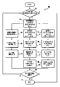
[0037] Figure 6 is a flowchart illustrating an embodiment of a
method for
controlling engine braking in the vehicle of Fig. 1; and
Date Recue/Date Received 2022-04-22
- 7 -
[0038] Figure 7 is a graph illustrating engine torque relative to
vehicle speed
for various modes of operations of the vehicle of Fig. 1.
DETAILED DESCRIPTION
[0039] The present technology will be described with reference to a
four-
wheeled straddle-seat all-terrain vehicle (ATV) 10. However, it is
contemplated that
aspects of the present technology could be used in other types of wheeled
vehicles, such
as side-by-side vehicles of road vehicles, motorcycles, dune buggies, and the
like and
other types of land vehicles, such as a snowmobile for example.
[0040] With reference to Figure 1, the ATV 10 has a front end 2 and
a rear end
4 defined consistently with a forward travel direction of the ATV 10. The ATV
10 has
a frame 12 to which a vehicle body is mounted. A pair of front wheels 16 is
suspended
from the front portion of the frame 12 via front suspensions 24. A pair of
rear wheels
18 is suspended from the rear portion of the frame 12 via rear suspensions 26.
Each of
the wheels 16, 18 has a tire 15 adapted for off-road conditions and traversing
rugged
terrain.
[0041] As illustrated in Figure 1, the ATV 10 also includes fairings
60 including
a front fascia 62 at the front end 2 of the ATV 10 and several side panels 64
extending
over lateral sides of the ATV 10. A fender 66 is disposed over each wheel 16,
18 to
protect the driver and/or passenger from dirt, water and other debris being
projected by
the rotating wheels 16, 18. The ATV 10 further includes a straddle-type driver
seat 28
mounted to the frame 12 for accommodating a driver of the ATV 10. Driver
footrests
50 are provided on either side of the driver seat 28 and are disposed
vertically lower
than the driver seat 28 to support the driver's feet. Another straddle-type
passenger seat
34 is provided behind the driver seat 28 to accommodate a passenger. A
passenger
footrest 52 is provided longitudinally rearward of each of the left and right
driver
footrests 50. The passenger footrests 52 are disposed slightly higher than the
driver
footrests 50 and designed to accommodate the feet of a passenger seated on the
passenger seat 34 which is disposed slightly vertically higher than the driver
seat 28. It
is contemplated that the passenger seat 34 and the passenger footrests 52
could be
omitted.
Date Recue/Date Received 2022-04-22
- 8 -
[0042] Each front suspension assembly 24 includes upper and lower A-
arms
(not shown), a front shock absorber 24c and a front coil spring 24d. The front
coil spring
24d is mounted over the front shock absorber 24c. The front coil spring 24d
and the
front shock absorber 24c are both pivotably connected at their lower ends to
the upper
A-arm and at their upper ends to the frame 12. The proximal ends of the upper
and
lower A-arms are pivotably connected to the frame 12. For each front
suspension
assembly 24, a kingpin (not shown) is mounted between the ends of the upper
and lower
A-arms. Each front wheel 18 is supported in part by its corresponding kingpin.
[0043] Each rear suspension assembly 26 comprises a swing arm (not
shown),
a rear shock absorber 26b and a rear coil spring 26c. Each swing arm has a
front end
pivotably connected to the frame 12 and a rear end supporting a wheel shaft
(not shown)
of its corresponding rear wheel 18. Each swing arm 26a is connected at mid-
length to
a torsion bar 58. For each rear suspension assembly 26, the rear shock
absorber 26b and
the rear coil spring 26c each have an upper end pivotally connected to the
frame 12 and
a lower end pivotally connected to its corresponding swing arm.
[0044] A steering assembly 30 is rotationally supported by the frame
12 to
enable a driver to steer the ATV 10. The steering assembly 30 includes a
handlebar
assembly including a handlebar 32 connected to a steering column (not shown)
for
actuating steering linkages (not shown) operatively connected to left and
right front
wheels 16. It is contemplated that the steering assembly 30 could include a
power
steering assembly. It is contemplated that a steering device other than a
handlebar could
be provided, such as, but no limited to, a steering wheel.
[0045] As shown in Figure 4, a throttle operator in the form of a
thumb-actuated
throttle lever 91 is provided near the right end of the handlebar 32. The
throttle operator
91 is selectively actuated by the driver of the ATV 10 to request throttle
from the engine
20. The throttle lever 91 is pivotally connected to a switch housing 34
mounted near
the right end of the handlebar 32. A hand grip 36 is provided next to the
switch housing
34. A two-wheel drive/four-wheel drive (2WD/4WD) selector switch 38 is
provided
on the switch housing 34. The 2WD/4WD selector switch 38 allows the user to
select
whether the engine 20 drives only the two rear wheels 18 (i.e. two-wheel
drive) or all
four wheels 16, 18 (i.e. four-wheel drive) as will be described below. In the
present
embodiment, the 2WD/4WD selector switch 38 is a toggle switch, but it is
contemplated
Date Recue/Date Received 2022-04-22
- 9 -
that it could be another type of switch. An engine braking mode selector 206
is mounted
to a front of the switch housing 34, and is therefore connected to the
handlebar 32. The
engine braking mode selector 206 is in proximity to the throttle lever 91,
meaning that
the driver of the vehicle 10 can actuate the throttle lever 91 and then the
engine braking
mode selector 206 without having to change the position of his/her hand on the
hand
grip 36. The engine braking mode selector 206 is a button. By pressing the
button 206,
the driver of the vehicle 10 can cycle through the various engine braking
modes as will
be described in more detail below.
[0046] In an alternative embodiment shown in Figure 5, the throttle
operator is
a twist grip 91' located next to the switch housing 34. Other types of
throttle operators,
such as a finger-actuated throttle lever and a pedal, are also contemplated.
In the
alternative embodiment shown in Figure 5, the engine braking mode selector 206
is
replaced by an engine braking mode selector 206' mounted to a rear of the
switch
housing 34. The engine braking mode selector 206' is a multi-position switch,
with
each position corresponding to one of the engine braking modes. It is
contemplated that
the braking mode selector 206 or 206' could be another type of input device.
It is also
contemplated that the braking mode selector 206 or 206' could be located
elsewhere on
the vehicle 10. For simplicity, a remainder of the description will be made
with
reference to the throttle lever 91 and the braking mode selector 206 shown in
Figure 4.
It should be understood that the alternative embodiment illustrated in Figure
5 and the
other alternatives for the throttle operator and the braking mode selector
described
above could be used.
[0047] A throttle operator position sensor (TOPS) 85 (Figure 3) is
operatively
connected to the throttle operator 91 to sense a position of the throttle
operator 91. The
TOPS 85 sends a signal representative of this position to an electronic
control unit
(ECU) 200 (Figure 3) which, as will be described in greater detail below,
controls
operation of the engine 20.
[0048] A display cluster 125 is located forwardly of the handlebar
32 for
displaying information to the driver.
[0049] An internal combustion engine 20 is mounted to the middle portion of
the frame 12 and, as will be described in greater detail below, is operatively
connected
Date Recue/Date Received 2022-04-22
- 10 -
to the front and rear wheels 16, 18 in order to propel the ATV 10. In this
embodiment,
the engine 20 is a V-type engine having two cylinders. The cylinders are
disposed at an
angle to each other. Each cylinder has an intake port (not shown) connected to
an air
induction system delivering air into the engine 20. Each cylinder has a fuel
injector
injecting fuel into the engine 20 and a spark plug igniting the fuel-air
mixture to initiate
the combustion cycle. Each cylinder has an exhaust port connected to an
exhaust
manifold through which the exhaust gases are removed from the engine 20. It is
contemplated that other types of internal combustion engines could be used,
such as,
for example, an inline engine. It is also contemplated that the engine 20
could have only
one or more than two cylinders.
[0050] An air induction system of the engine 20 includes an intake
manifold, a
plenum chamber connected upstream of the intake manifold and a throttle body
68
(schematically shown in Figure 3) connected upstream of the plenum chamber.
When
the engine 20 is operating, air flows sequentially through the throttle body
68, the
plenum chamber, the intake manifold and then through the intake ports into the
cylinders of the engine 20. The intake manifold separates the flow of air into
multiple
branches, each of the branches being connected to an air intake port of a
corresponding
cylinder of the engine 20.
[0051] The throttle body 68 regulates the flow of air to the engine
20. The
throttle body 68 includes a throttle valve 75 (Figure 3). Adjusting the
position of the
throttle valve 75 inside the throttle body 68 regulates air flow through the
throttle body
68 to the engine 20. A throttle valve actuator 81 (e.g., an electric motor) is
mounted to
the throttle body 68 and is operatively connected to the throttle valve 75 to
pivot the
throttle valve 75 inside the throttle body 68, thereby changing a position of
the throttle
valve 75. The throttle valve 75 is pivotable between a closed position and a
fully open
position. The throttle valve 75 can also be pivoted to partially opened
positions
intermediate the closed and fully opened positions. The closed position of the
throttle
valve 75 is the position of the throttle valve 75 at which the flow of air
through the
throttle body 30 is most restricted. The fully open position of the throttle
valve 75 is to
position of the throttle valve 75 at which the flow of air through the
throttle body 68 is
least restricted. The angle of the throttle valve 75 at the closed and open
positions could
vary depending on the vehicle and the engine.
Date Recue/Date Received 2022-04-22
- 11 -
[0052] The throttle valve actuator 81 positions the throttle valve
75 based at
least in part on the position of the throttle operator 91. Notably, as
described above, the
TOPS 85 senses a position of the throttle operator 91 and sends a signal
representative
of this position to the ECU 200. Based on this signal and other signals, the
ECU 200
sends a signal to the throttle valve actuator 81 to adjust the position of the
throttle valve
75 and thus an opening of the throttle body 68. A throttle valve position
sensor 230
(Figure 3) senses the position of the throttle valve 75 in the throttle body
68 and sends
a throttle valve position signal representative of this position to the ECU
200.
[0053] Engine power, torque and engine speed are determined in part
by the
fuel-air mixture in the engine 20 and the ignition timing. The ECU 200
therefore
regulates fuel injection into the engine 20 as well as the ignition timing by
controlling
operation of the fuel injectors and the spark plug or their equivalents.
[0054] With reference to Figure 2, a drivetrain of the ATV 10
includes the
engine 20, a continuously variably transmission (CVT) 102 and a transmission
117. An
output shaft 107 of the engine 20 is connected to the CVT 102 which, as will
be
described in greater detail below, is in turn connected to the transmission
117.
[0055] A gear selector handle (not shown) is configured to be
selectively moved
between positions P. N, R, L, H (respectively corresponding to a parking,
neutral,
reverse, low and high gears) and allows the driver of the ATV 10 to make a
gear
selection. It is contemplated that the sequence of gears could be different.
The gear
selector handle is connected to the transmission 117 for effecting the gear
selection.
The transmission 117 is disposed rearward of the engine 20. The transmission
117
transfers torque from a transversely extending driven shaft 109 to the
longitudinally
extending front and rear driveshafts (103, 101). The transmission 117 includes
different
gear sets, the combination of the gear sets being selected based on the
position of the
gear selector.
[0056] As shown in Figure 2, the CVT 102 is disposed on a left side
of the
engine 20. The CVT 102 includes a drive pulley 111 disposed on the output
shaft 107
of the engine 20, a driven pulley 113 disposed on the driven shaft 109 for
rotation
therewith, and a CVT belt 105 disposed around both pulleys 111, 113 to
transmit torque
from the drive pulley 111 to the driven pulley 113. A housing 106 (Figure 1)
of the
Date Recue/Date Received 2022-04-22
- 12 -
CVT 102 is connected to both the engine 20 and the transmission 117. The
driven shaft
109 is connected to the transmission 117 for transmitting thereto the torque
output of
the engine 20.
[0057] Each of the pulleys 111, 113 includes a movable sheave that
can move
axially relative to a fixed sheave to modify an effective diameter of the
corresponding
pulley 111, 113. The drive pulley 111 is a centrifugal pulley in that the
sheaves thereof
move in response to a centrifugal force applied thereon caused by changes in
engine
speed and torque requirement of the wheels 16, 18. The effective diameters of
the
pulleys 111, 113 are in inverse relationship. In the illustrated embodiment,
the CVT
102 is a purely mechanical CVT 102, in which the effective diameter of the
drive pulley
111 increases with increasing rotational speed of the drive pulley 111 (i.e.
with
increasing engine speed). The effective diameter of the driven pulley 113
therefore
decreases when the torque required at the driven shaft 109 (connected to the
wheels 16,
18) increases. The CVT 102 may thus be referred to as an "unassisted" CVT in
that a
gear ratio of the CVT 102 (i.e., an effective diameter of the driven pulley
113 over the
effective diameter of the drive pulley 111) is automatically mechanically
adjusted in
accordance with the speed of the engine 20 and the torque requirement of the
wheels
16, 18. It is contemplated that an "assisted" CVT, in which the effective
diameter of at
least one of the pulleys 111, 113 can be modified by an actuator independently
of engine
speed, could be used.
[0058] As shown in Figure 2, the ATV 10 has a front differential 76
adapted to
receive, via a driveshaft 80 a torque from the engine 20. On each of its left
and right
sides, the front differential 76 is connected to a half shaft 78. The front
differential 76
transmits the torque to the front wheels 16 via the front half shafts 78.
Depending on
riding conditions, the front differential 76 may send unequal torque to the
two front
wheels 16 so that the left front wheel 16 and the right front wheel 16 may
rotate at
different speeds.
[0059] It is contemplated that, in some embodiments, the
differential 76 could
be a locking differential whereby the differential can be switched between a
locked
configuration and an open configuration. In the locked configuration, the
wheels 16 are
locked into the same rate of rotation and both wheels 16 receive the same
amount of
Date Recue/Date Received 2022-04-22
- 13 -
power. In the open configuration, the wheels 16 are allowed to freely rotate
at different
rates, similar to an open differential, for example for negotiating a turn.
[0060] The ATV 10 includes a rear spool gear assembly 97 driven by
the rear
driveshaft 101. The driveshaft 101 is driven by the transmission 117. On each
of its left
and right sides, the rear spool gear assembly 97 is connected to a half shaft
98. Another
CV joint 145 is connected to an opposed end of each half shaft 98. The rear
spool gear
assembly 97 transmits the torque to the rear wheels 18 via the rear half
shafts 98.
Alternatively, in some embodiments, the torque from the engine 20 could be
transmitted
to the rear wheels 18 by an open differential, a limited slip differential, or
a locking
differential instead of by the rear spool gear assembly 97.
[0061] As described above, the ATV 10 can be operated in a two-wheel
drive
mode in which only the rear wheels 18 are driven by the engine 20 or in a four-
wheel
drive mode in which the front wheels 16 and the rear wheels 18 are driven by
the engine
based on the position of the 2WD/4WD selector switch 38. To that end, in this
15 embodiment, the transmission 117 is selectively connected to the front
wheels 16 via a
drive mode coupler 115, shown schematically in Figure 2. As depicted in Figure
3, the
drive mode coupler 115 is controlled by the ECU 200 and is selectively
actuated to
cause the ATV 10 to change from the two-wheel drive mode configuration to the
four-
wheel drive mode configuration by selectively coupling the driveshaft 80 to
the
20 driveshaft 103 for selectively driving the front wheels 16. Such drive
mode couplers
are known in the art and will thus not be described in detail herein.
[0062] Therefore, when the ATV 10 is in the two-wheel drive mode, a
torque
output of the engine 20 is applied via the CVT 102 and the transmission 117 to
the left
and right rear wheels 18. Conversely, when the ATV 10 is in the four-wheel
drive mode,
a portion of the torque output of the engine 20 is applied to each of the
front wheels 16
and rear wheels 18 via the CVT 102 and the transmission 117.
[0063] While the ATV 10 is described with the rear wheels 18 driving
the
vehicle when in the two-wheel drive mode, it is contemplated that the ATV 10
could
implement a front wheel drive mode in other embodiments (i.e., in the two-
wheel drive
mode, the front wheels 16 are driven by the engine 20 rather than the rear
wheels 18).
Date Recue/Date Received 2022-04-22
- 14 -
[0064] As shown in Figure 3, the ECU 200 has a processor unit 202
for carrying
out computer executable instructions, and a non-transitory memory module 204
that
stores the computer executable instructions in a non-transitory medium (not
shown)
included in the memory module 204. The processor unit 202 includes one or more
processors for performing processing operations that implement functionality
of the
ECU 200. The processor unit 202 may be a general-purpose processor or may be a
specific-purpose processor comprising one or more preprogrammed hardware or
firmware elements (e.g., application-specific integrated circuits (ASICs),
electrically
erasable programmable read-only memories (EEPROMs), etc.) or other related
elements. The non-transitory medium of the memory module 204 may be a
semiconductor memory (e.g., read-only memory (ROM) and/or random-access
memory (RAM)), a magnetic storage medium, an optical storage medium, and/or
any
other suitable type of memory. While the ECU 200 is represented as being one
entity
in this implementation, it is understood that the ECU 200 could comprise
separate
entities for controlling components separately.
[0065] The ECU 200 is in communication with a plurality of sensors
of the
ATV 10 in order to control operation of the ATV 10. For instance, as shown in
Figure
3, the ECU 200 is in communication with, amongst other sensors, the throttle
operator
position sensor 85, wheel speed sensors 210 for sensing rotational speeds
representative
of the rotational speeds of the front wheels 16 and the rear wheels 18, an
engine torque
sensor 220 to sense a torque output of the engine 20, the throttle valve
position sensor
230, and an engine speed sensor 222 sensing a speed of rotation of the
crankshaft of the
engine 20 or the speed of rotation of the output shaft 107. Other sensors are
also
contemplated.
[0066] In this embodiment, the rotational speeds representative of the
rotational
speeds of the front and rear wheels 16, 18 that are sensed by the wheel speed
sensors
210 are the rotational speeds of the front and rear wheels 16, 18. In other
embodiments,
the rotational speeds representative of the rotational speeds of the front and
rear wheels
16, 18 could be the rotational speeds of the wheels 16, 18, or the rotational
speeds of
shafts connected to the wheels 16, 18, or the rotational speeds of the driven
pulley 113
connected to the wheels 16, 18, or any other speeds from which the rotational
speeds
of the wheels 16, 18 could be inferred. In the present embodiment, the wheel
speed
Date Recue/Date Received 2022-04-22
- 15 -
sensors 210 are used as vehicle speed sensors. As the diameter of the wheels
16, 18 is
known, the signal sent from the wheel speed sensors 210 to the ECU 200 is
indicative
of the speed of the vehicle 10 and is used by the ECU 200 to determine the
speed of the
vehicle 10. In alternative embodiments, the vehicle speed sensor can be a
global
positioning system that can determine the distance travelled over time to
provide a
signal indicative of the speed of the vehicle 10 to the ECU 200. In other
alternative
embodiments, by determining the transmission ratio between the engine 20 and
the
wheels 16, 18, the engine speed sensor 222 can be used as the vehicle speed
sensor.
[0067] The torque output of the engine 20 is measured by an engine
torque
sensor 220 communicating with the ECU 200 to send a signal representative of
engine
torque to the ECU 200. Alternatively, the engine torque sensor 220 can be
omitted, and
the torque output of the engine 20 can be calculated by the ECU 200 or
obtained from
control maps by the ECU 200 based on the rotational speed output of the engine
20,
fuel injection into the cylinders thereof and the ignition timing of the
engine 20.
[0068] The ATV 10 includes other components such as an exhaust system,
radiators, headlights, and the like. As it is believed that these components
would be
readily recognized by one of ordinary skill in the art, further explanation
and description
of these components will not be provided herein.
[0069] Turning now to Figure 6, a method 300 for controlling engine
braking
in the vehicle 10 will be described. The computer executable instructions
required for
the ECU 200 to execute the method 300 are stored in the memory of the ECU 200.
[0070] The method 300 allows a driver of the vehicle 10 to select a
desired level
of engine braking provided by the engine 20 when the driver fully releases the
throttle
operator 91. To select the desired engine braking mode, the driver actuates
the engine
braking mode selector 206 until the desired engine braking mode is selected.
The
currently selected engine braking mode is displayed on the display cluster
125.
[0071] In the present embodiment, the driver can select between
three different
engine braking modes (i.e. Mode A, Mode B, Mode C). Mode A provides the
greatest
level of engine braking, that is to say that under mode A, the engine 200 will
provide
the most engine braking of the three modes and the deceleration of the vehicle
10 due
to engine braking will be the greatest. Mode B provides a level of engine
braking that
Date Recue/Date Received 2022-04-22
- 16 -
is smaller than in mode A. Under mode B, the engine 200 will provide less
engine
braking than in mode A. Mode C provides the least level of engine braking.
Under
mode C, the engine 200 will provide less engine braking than in mode A and
mode B.
It is contemplated that in alternative embodiments the drivers could select
between only
two or more than three engine braking modes.
[0072] It is contemplated that in alternative embodiments, the
vehicle 10 could
be provided with a driving mode selector allowing the driver to select between
different
driving modes such as a "trail mode", a "comfort mode" and a "sport mode" for
example. The different driving modes may have different engine acceleration
and
suspension adjustments for example. In such embodiments, the different driving
modes
have different associated engine braking modes. As such, by selecting a
driving mode,
the user also selects an engine braking mode associated with the driving mode.
Therefore, in such embodiments, since the driving mode selector also selects
an engine
braking mode associated with the selected driving mode, the driving mode
selector is
considered to correspond to an engine braking mode selector.
[0073] At 302, the ECU 200 determines if the throttle operator 91 is
its fully
released position based on the signal received from the TOPS 85. In the
present
embodiment, the throttle operator 91 is normally biased toward its fully
released
position. As such, when the driver lets go of the throttle operator 91, the
throttle
operator 91 automatically moves to its fully released position. If at 302 the
throttle
operator 91 is not at its fully released position, then at 304 the ECU 200
continues
normal control the engine 20 and the position of the throttle valve 75 (i.e.
without
controlling the engine 20 and the position of the throttle valve 75 according
to one of
the engine braking modes). If at 302 the throttle operator 91 is at its fully
released
position, then the ECU 200 proceeds to 306. At 306, the ECU 200 determines
which
one of the three engine braking modes has been selected using the engine
braking mode
selector 206.
[0074] If at 306, the selected engine braking mode is mode A, then
at 308 the
ECU 200 controls the engine 20 and the position of the throttle valve 75
according to
mode A to apply the greatest level of engine braking of the three modes.
Controlling
the engine 20 and the position of the throttle valve 75 according to mode A
includes
closing the throttle valve 75 (i.e. moving it to its closed position) at 310
and stopping
Date Recue/Date Received 2022-04-22
- 17 -
to inject fuel at 312. It is contemplated that 312 could be performed before
310 or that
310 and 312 could be performed simultaneously. As a result, the engine 20
causes
engine braking which slows down the vehicle 10. As can be seen with reference
to the
Mode A line in Figure 7 (i.e. the dashed-dot line), the resulting engine
torque is a
negative engine torque which increases as the speed of the vehicle 10
decreases. The
slope and shape of the Mode A line will depend on the construction of the
engine 20
and its associated components. The engine braking mode A corresponds to the
type of
engine braking that typically occurs in vehicles. It is contemplated that in
some
embodiments, at 310 the throttle valve 75 could be slightly opened and/or at
312 there
could be a small amount of fuel injection. For example, it is contemplated
that at 310,
the throttle valve 75 could be opened by about 2 or 3 percent.
[0075] As can be seen in Figure 7, an engine torque of zero is
reached at point
TO before the vehicle 10 reaches a speed of zero. This is because when the
vehicle 10
reaches the speed corresponding to point TO, the centrifugal drive pulley 111
of the
CVT 102 does not turn fast enough to clamp the belt 105 and as a result the
drive pulley
111 turns relative to the belt 105. It is contemplated that in embodiments
having an
assisted CVT 102, the belt 105 could be clamped at lower speeds of rotation of
the drive
pulley 111 such that engine braking could be applied until the vehicle 10
stops.
[0076] From 312, the ECU 200 proceeds to 314. At 314 the ECU 200
determines an engine speed of the engine 20 based on the signal received from
the
engine speed sensor 222. If at 314 the engine 20 has not reached its idle
speed, then
the ECU 302 returns to 302. If at 314 the engine 20 has reached its idle
speed, then the
ECU 200 stops controlling the engine 20 and the position of the throttle valve
75
according to the selected engine braking mode (mode A in this case) and
proceeds to
304 where the engine 20 and the position of the throttle valve 75 will be
controlled to
maintain the engine 20 at idle speed until the throttle operator 91 is
actuated.
[0077] Returning to 306, if the selected engine braking mode is mode
B, then
at 316 the ECU 200 controls the engine 20 and the position of the throttle
valve 75
according to mode B to apply a level of engine braking that is less than the
level of
engine braking of mode A. Controlling the engine 20 and the position of the
throttle
valve 75 according to mode B includes moving the throttle valve 75 to a
partially open
position A at 318, injecting a fuel amount X at 320 and retarding ignition by
J degrees
Date Recue/Date Received 2022-04-22
- 18 -
at 322. It is contemplated that 318, 320 and 322 could be performed in a
different order
and/or that two or more of 318, 320, 322 could be performed simultaneously. To
obtain
the position A of the throttle valve 75, the fuel amount X and the number of
degrees J,
the ECU 200 first determines the speed of the vehicle 10. The ECU 200 then
determines
values of A, X and J that will result in the engine 20 producing an engine
torque
corresponding to the engine torque on the Mode B line in Figure 7 (i.e. the
dashed line)
for this speed of the vehicle 10. As manners in which throttle valve position,
fuel
injection and ignition can be controlled to obtain a target torque are known,
this will
not be described in detail herein. As can be seen with reference to the Mode B
line in
Figure 7, the engine torque in mode B is a negative engine torque which
increases as
the speed of the vehicle 10 decreases. As in mode A, in mode B an engine
torque of
zero is reached at point TO before the vehicle 10 reaches a speed of zero for
the same
reasons as those explained above. The slope and shape of the Mode B line could
be
different than illustrated. As can be seen by comparing the Mode B line to the
Mode A
line in Figure 7, for any given speed of the vehicle 10 above the speed at TO
the engine
torque is smaller in mode A than in mode B, as such for any given speed of the
vehicle
10 above the speed at TO the level of engine braking in greater in mode A than
in mode
B. It is contemplated that in embodiments where the throttle valve 75 is kept
slightly
opened at 310 in mode A, the position A of the throttle valve 75 could be the
same as
the slightly opened position at 310 in mode A. From 322, the ECU 200 proceeds
to
314 which is then performed as described above.
[0078] Returning once again to 306, if the selected engine braking
mode is
mode C, then at 324 the ECU 200 controls the engine 20 and the position of the
throttle
valve 75 according to mode C to apply a level of engine braking that is less
than the
level of engine braking of modes A and B. Controlling the engine 20 and the
position
of the throttle valve 75 according to mode C includes moving the throttle
valve 75 to a
partially open position B at 326, injecting a fuel amount Y at 328 and
retarding ignition
by K degrees at 330. It is contemplated that 326, 328 and 330 could be
performed in a
different order and/or that two or more of 326, 328, 330 could be performed
simultaneously. To obtain the position B of the throttle valve 75, the fuel
amount Y
and the number of degrees K, the ECU 200 first determines the speed of the
vehicle 10.
The ECU 200 then determines values of B, Y and K that will result in the
engine 20
producing an engine torque corresponding to the engine torque on the Mode C
line in
Date Recue/Date Received 2022-04-22
- 19 -
Figure 7 (i.e. the dotted line) for this speed of the vehicle 10. As manners
in which
throttle valve position, fuel injection and ignition can be controlled to
obtain a target
torque are known, this will not be described in detail herein. As can be seen
with
reference to the Mode C line in Figure 7, the engine torque in mode C is a
positive
engine torque which decreases as the speed of the vehicle 10 decreases. The
positive
engine torque is less than an engine torque needed to maintain the vehicle at
its current
vehicle speed, which is illustrated by the solid line Constant V in Figure 7,
as such
engine braking occurs and the vehicle 10 decelerates. As in modes A and B, in
mode
C an engine torque of zero is reached at point TO before the vehicle 10
reaches a speed
of zero for the same reasons as those explained above. The slope and shape of
the Mode
C line could be different than illustrated. As can be seen by comparing the
Mode C line
to the Mode B line in Figure 7, for any given speed of the vehicle 10 above
the speed
at TO the engine torque is smaller in mode B than in mode C, as such for any
given
speed of the vehicle 10 above the speed at TO the level of engine braking in
greater in
mode B than in mode C. In order to achieve the greater engine torques in mode
C
compared to mode B, for any given speed of the vehicle 10 above the speed at
TO, the
throttle valve 75 is more open in position B than in position A, the fuel
amount Y is
greater than the fuel amount X, and the number of degrees K is less than the
number of
degrees J. It is contemplated that in some embodiments, the position B of the
throttle
valve 75 could be the same as the position A. From 330, the ECU 200 proceeds
to 314
which is then performed as described above.
[0079] It is contemplated that the manner in which the engine 20 and
the
position of the throttle valve 75 are controlled according to the engine
braking mode B
or C could differ from the one described above. For example, it is
contemplated that
322 and 330 could be omitted. In another example, fuel injection and ignition
could be
disabled in one of the two cylinders such that fuel injection and ignition
would be
controlled in only one of the cylinders.
[0080] When the ECU 200 arrives at 306 from 314 via 302, should the
selected
engine braking mode have changed, the ECU 200 will control the engine 20 and
the
position of the throttle valve 75 to control the engine torque in order to
smoothly
transition from the engine torque corresponding to the previously selected
engine
braking mode to the engine torque corresponding to the newly selected engine
braking
Date Recue/Date Received 2022-04-22
- 20 -
mode. It is also contemplated that once 306 has been performed once, the
engine
braking mode could not be changed until the method ends at 304 and then starts
again
at 302 even if the engine braking mode selector 206 is actuated while the
method 300
is performed. In an alternative embodiment, 306 could be performed before 302
and
314 would still return to 302. As a result, the engine braking mode could not
be changed
while the method 300 is being performed.
[0081] It is contemplated that in an alternative embodiment of the
method 300,
the ECU 200 could control the engine 20 and the position of the throttle valve
75 to
obtain a desired deceleration of the vehicle 10 instead of a desired engine
torque as
described above, with each engine braking mode corresponding to a different
deceleration profile. The deceleration of the vehicle 10 can be determined
from the
change in the speed of the vehicle 10 over time or by an accelerometer
provided on the
vehicle 10.
[0082] Modifications and improvements to the above-described
embodiments
of the present technology may become apparent to those skilled in the art. The
foregoing
description is intended to be exemplary rather than limiting. The scope of the
present
technology is therefore intended to be limited solely by the scope of the
appended
claims.
Date Recue/Date Received 2022-04-22