Note : Les descriptions sont présentées dans la langue officielle dans laquelle elles ont été soumises.
CA 03157241 2022-04-07
WO 2021/089514 PCT/EP2020/080765
A UNIVERSAL JOINT WITH IMPROVED STIFFNESS
DESCRIPTION
TECHNICAL FIELD
[0001] The present invention relates to the fields of power transmitting drive
shafts.
In particular, embodiments described herein refer to drive shafts to be used
in
agricultural machinery.
BACKGROUND TO THE INVENTION
[0002] Telescopic drive shafts are commonly used for transmitting power from a
power source to an operating machine that can move relative to the power
source. In
many applications, the power take-off of the power source and the input shaft
of the
operating machine reciprocally move in such a way that the transmission shaft
has to
take different angular positions.
[0003] This need is particularly significant in agriculture, where operating
machines
of different kinds are connected to a tractor that constitutes the power
source. The
tractor is used to move the operating machine, as well as to supply it with
power. The
power source and the operating machine are mechanically connected through a
drive
shaft.
[0004] A drive shaft is generally constituted by a telescopic shaft and two
end
universal joints. The telescopic shaft comprises an outer tubular shaft,
inside which an
inner shaft, usually tubular, is slidable inserted. The outer shaft and the
inner shaft,
also called tubes, are torsionally coupled together, for instance through a
spline, to
allow torque transmission from one to the other. One of the end universal
joints is
connected to an end of the outer shaft forming the telescopic shaft, whilst
the other
universal joint is connected to an opposite end of the inner shaft. One of the
two
universal joints is used to couple the drive shaft to the power take-off of
the power
source, whilst the other is used to couple the drive shaft to the power take-
off of the
driven machine. This drive shaft allows the power source and the driven
machine to
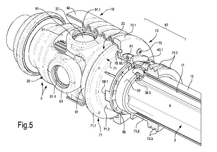
move relative to each other, keeping the reciprocal mechanical connection.
[0005] In use, due to the mutual displacements of the power source and the
driven
CA 03157241 2022-04-07
WO 2021/089514 -2- PCT/EP2020/080765
machine, the outer shaft and the inner shaft slide with respect to each other
when
rotating under load.
[0006] An accident-preventing protection covers the telescopic shaft and at
least part
of the end universal joints.
[0007] Lubrication systems have been developed for improving the operation of
the
telescopic shaft, which are adapted to lubricate the surfaces of the inner
shaft and of
the outer shaft in sliding contact with one another. W098/58183 and
US5,173,082,
US6,511,379 and EP 2520813 disclose lubrication systems for lubricating the
inner
and outer tubular shafts forming the telescopic shaft. These lubrication
systems have
allowed significantly improving the telescopic shaft operation conditions.
However,
these lubrication systems can be further improved, especially as regards the
number of
required greasing interventions.
[0008] Modern telescopic shafts have splined profiles with a plurality of
longitudinal
projections shaped like tabs or lobes, extending longitudinally according to
the axis of
the telescopic shaft. An example of this kind of splined profiles is disclosed
in
US 5,718,266. In these telescopic shafts, torque and power are transmitted
through the
contact between a flank of each longitudinal projection of the inner tubular
shaft and
a corresponding flank of a groove of the outer tubular shaft. In the contact
area, high
pressure is generated. The more elongated the telescopic shaft is, the higher
the
pressure is, because of the reduced axial extension of the contact surface due
to the
extraction of the inner shaft from the outer shaft. The pressure between the
mutually
co-acting surfaces of the inner and outer tubular shafts generates friction,
and thus
wear of the mechanical components, as well as resistance against axial
sliding,
adversely affecting the transmission operation.
[0009] W098/58183 discloses a drive shaft of the type described above,
provided
with an accident-preventing protection. This protection comprises a telescopic
tubular
protection surrounding the outer shaft and the inner shaft of the drive shaft
and formed
by a first guard tube and a second guard tube, inserted into the first one,
that can slide
with respect to each other to follow the drive shaft shortening and
lengthening
movements. The accident-preventing protection further comprises end boots for
each
of the two universal joints of the drive shaft. Each end boot is fastened to
the telescopic
CA 03157241 2022-04-07
WO 2021/089514 -3- PCT/EP2020/080765
tubular protection, more precisely to one of the two guard tubes forming it,
and may
have a flexible hood integral with a rigid annular structure. The end boot is
fastened to
the inner fork of the respective universal joint through the rigid annular
structure. Each
rigid annular structure comprises an annular sliding block slidably engaged in
an
annular groove provided on the sleeve of the inner fork of the respective
universal
joint. Each end boot further comprises a lubrication system, adapted to
lubricate with
lubricating grease the surfaces, formed by the annular sliding block and the
annular
groove, in sliding contact with one another.
[0010] The lubricating grease reduces during operation, and is partially
dispersed in
the environment. To operate properly, the accident-preventing protection
therefore
needs frequent greasing interventions, requiring to shut the machine, in which
the drive
shaft is installed, down, and to add lubricant, typically using a greasing
nipple, to keep
the mutually touching and mutually sliding surfaces of the annular groove and
the
annular sliding block sufficiently greased.
[0011] In these known drive shafts, the need for frequent greasing
interventions is a
drawback. It would be therefore useful and advantageous to have available a
drive
shaft with respective accident-preventing protection, allowing reducing the
greasing
interventions.
[0012] Greasing problems arise also for the universal joints, and more
specifically
for the needle bearings interposed between the spider trunnions and the seats
of the
trunnions in the arms of the forks of the end universal joints. Inevitably,
the lubricant
grease leaks through the bearing seals, and this requires continuous refilling
through
greasing operations.
[0013] Moreover, especially in agricultural applications, the universal joints
are
subjected to significant dynamic stresses, due to the fact that the joints of
the drive
shaft operate with a significant angular offset. Furthermore, in these
applications very
high torques shall be transmitted. All this results in high dynamic stresses
on the
bearings of the universal joints.
[0014] It would be therefore useful and advantageous to have available drive
shafts
requiring fewer greasing interventions, or even no greasing of the joints. It
would be
also advantageous to optimize the operating conditions of the joints under
load.
CA 03157241 2022-04-07
WO 2021/089514 -4- PCT/EP2020/080765
[0015] In general, it would be therefore advantageous to have available a
drive shaft
which completely or partially overcomes at least some of the drawbacks of the
prior
art drive shafts, above all as regards greasing requirements and useful life
of the
wearable components.
SUMMARY
[0016] To overcome, at least partially, the drawbacks of the prior art drive
shafts, a
device according to claim 1 is suggested.
[0017] Particularly advantageous embodiments are defined in the dependent
claims.
BRIEF DESCRIPTION OF THE DRAWING
[0018] The invention will be better understood by following the description
below
and the attached drawing, showing a non-limiting embodiment of the invention.
More
specifically, in the drawing:
Fig.1 shows a cross-section of a drive shaft according to a plane containing
the shaft axis;
Fig.2 shows a cross-section according to the line II-II of Fig.1;
Fig.3 shows an enlargement of a first end of the drive shaft of Fig.1;
Fig.4 shows an enlargement of the other end of the drive shaft of Fig.1;
Fig. 4A shows an enlarged cross-section of the detail indicated by the letter
A in Fig. 4;
Fig.5 is an enlarged and partially cut-away isometric view of the end of Fig.3
of the drive shaft;
Fig.6 is an enlarged and partially cut-away isometric view of the end of Fig.4
of the drive shaft;
Fig.7 shows the end of the drive shaft illustrated in Fig.5, with some parts
removed;
Fig.8 shows the end of the drive shaft illustrated in Fig.6 with some parts
removed;
Fig.9 is a cut-away isometric view of the inner shaft with the lubricating
system of the telescopic shaft;
Fig.10 is a view according to X-X of Fig.9;
Figs. 11 and 12 are isometric views, according to two different angles, of the
CA 03157241 2022-04-07
WO 2021/089514 -5- PCT/EP2020/080765
lubricant distribution block of the system of Fig.9;
Fig.13 is a front view according to XIII-XIII of Fig.12.
Fig. 14 is a cross-section according to the line XIV-XIV of Fig.13;
Fig.15 shows a cross-section according to XV-XV of Fig.14;
Figs. 16 and 17 are isometric views, according to two different angles, of the
block where the lubricant receiving chamber of the lubrication system of Fig.9
is
realized;
Fig.18 shows a cross-section according to XVIII-XVIII of Fig.17;
Fig.19 shows a cross- section according to XIX-XIX of Fig.18;
Fig.20 is a side view of one of the inner forks of the universal joints of the
drive shaft of Fig.1;
Fig.21 shows a cross-section according to the plane with trace XXI-XXI of
Fig.22 of the inner fork of Fig.20;
Fig.22 shows a cross-section according to a plane with trace XXII-XXII of
Figs.20 and 21;
Fig.23 is a side view, analogous to that of Fig.20, of one of the outer forks
of
the universal joints of the drive shaft of Fig.1;
Fig.24 shows a cross-section according to a plane with trace XXIV-XXIV of
Fig.25;
Fig.25 shows a cross-section according to the plane with trace XXV-XXV of
Figs. 23 and 24;
Fig.26 shows a cross-section of one of the spiders of the universal joints of
the shaft of Fig.1 according to a plain containing the axes of the four
trunnions of the
spider, according to t plane with trace XXVI-XXVI of Fig.27;
Fig.27 shows a cross-section according to a plane with trace XXVII-XXVII
of Fig.26;
Fig.28 shows an enlargement of a bearing of the spider of Figs.26 and 27; and
Figs. 29 and 30 show cross-sections of the inner shaft and the outer shaft,
respectively, of the drive shaft of Fig. 1.
DETAILED DESCRIPTION
[0019] In the following description and the attached claims, the term
"approximately" indicates a quantity that is approximate, with an
approximation of
+/- 15%, preferably +/- 10% and in some instances preferably +/- 5%. In other
words,
CA 03157241 2022-04-07
WO 2021/089514 -6- PCT/EP2020/080765
"approximately A" refers to an interval comprised between (A+0,15A) and (A-
0,15A),
and preferably between (A+0,1A) and (A-0,1A), or between (A+0,05A) and (A-
0, 05A).
[0020] Fig.1 shows a cross-section, according to a longitudinal plane
containing the
rotation axis, of a drive shaft 1; Figs.2 to 8 show enlargements of the two
ends of the
drive shaft 1, in some cases with cut-away and/or removed parts.
[0021] With reference to Figs. 1 to 9, the drive shaft 1 generally comprises a
power
transmitting telescopic shaft 3 with two ends; with these ends, a first
universal joint 5
and a second universal joint 7 are associated. As better detailed below, the
universal
joints 5 and 7 have connection means for connecting to power take-offs of the
power
source and of the load, i.e. a driven machine for instance.
[0022] The telescopic shaft 3 comprises two tubular elements, simply called
"telescopic tubes", one of which is inserted inside the other. More in
particular, in the
embodiment of Fig.1 the telescopic shaft 3 comprises a first tubular element,
here
below referred to as outer tubular shaft or simply outer shaft 9, and a second
element,
that is tubular in the illustrated example, referred to as inner tubular shaft
or simply
inner shaft 11.
[0023] The inner shaft 11 is inserted in the outer shaft 9 in telescopic
fashion, and
both are so shaped as to slide with respect to each other parallel to the axis
A-A of the
telescopic shaft; however, the respective cross-sections of the shafts are
such that the
shafts cannot rotate with respect to each other. This means that the shafts
are
torsionally coupled together so as to rotate integrally and to transmit power
from a
power source (not shown) to a user, i.e. a load, constituted for example by a
driven
machine or an operating machine (not shown).
[0024] As shown in particular in the cross-section of Fig.2, the shafts 9 and
11 have
a non-circular tubular wall, so as to torsionally couple together. More in
particular, the
shape of the cross-section of both the shafts 9 and 11 has four longitudinal
projections,
through which the two tubular shafts 9 and 11 engage. Specifically, the inner
shaft 11
has four longitudinal projections 11.1, engaging inside grooves provided at as
many
longitudinal projections 9.1 of the outer shaft 9. More details on the
configurations of
the shafts 9 and 11 will be described below.
CA 03157241 2022-04-07
WO 2021/089514 -7- PCT/EP2020/080765
[0025] The universal joint 5 is connected to an end of the inner shaft 11 and
comprises a first fork 23 and a second fork 25, joined together by means of a
spider
27. Here below, the fork 23 will be also called inner fork, whilst the fork 25
will be
called outer fork. The inner fork 23 is rigidly connected to the first end of
the inner
shaft 11 of the telescopic shaft 3, whilst the outer fork 25 may be connected
to a
power take-off or to any other member of a mechanical transmission line, not
shown,
of which the drive shaft 1 is part.
[0026] Analogously to the universal joint 5, also the universal joint 7
comprises a
first fork (inner fork), indicated again with reference number 23, and a
second fork
(outer fork) indicated again with reference number 25, joined together by
means of a
spider indicated again with reference number 27. The inner fork 23 is rigidly
connected
to a first end of the outer shaft 9, whilst the outer fork 25 may be connected
to a power
take-off or to any other member of a mechanical transmission line, not shown.
[0027] The drive shaft 1 also comprises an accident-preventing protection 13.
The
accident-preventing protection 13 comprises a telescopic tubular protection
formed by
a pair of tubular elements 15, 17, one of which is slidable inserted in the
other. The
tubular elements 15, 17 (here below referred to simply as "tubes") are
preferably so
shaped as to be torsionally coupled, i.e. they cannot rotate with respect to
each other
around the axis A-A of the telescopic shaft 3, but they can axially slide in
the direction
of the axis A-A. In this way, the accident-preventing protection 13 can follow
the
lengthening and shortening movements of the drive shaft 1. The shape of the
cross-
section of the tubes 15, 17 is visible in Fig.2. The tubes 15, 17 have a non-
circular
cross-section, for preventing the mutual rotation thereof More in particular,
in the
illustrated example the two tubes 15, 17 of the accident-preventing protection
13
comprise projections 15.1 and 17.1, the ones inserted into the others and
sliding with
respect to one another in the direction of the axis A-A.
[0028] In addition to the tubes 15 and 17, the accident-preventing protection
13
further comprises two ends protections 19, one of which is associated with the
universal joint 5 and the other with the universal joint 7. More details on
the
configurations of the end protections 19 will be described below.
[0029] In the illustrated embodiment, the telescopic shaft 3 is provided with
a
CA 03157241 2022-04-07
WO 2021/089514 -8- PCT/EP2020/080765
lubrication system 37 housed inside the inner tubular shaft 11. Figs. 9 to 19
show the
components of the lubrication system in detail. The lubrication system 37 is
adapted
to supply lubricant, in particular lubricating grease, in the gap between the
inner shaft
11 and the outer shaft 9 forming the telescopic shaft 3.
[0030] For the sake of clarity of representation, in Fig.9 the lubrication
system 37
and the inner shaft 11 are shown separately from the other components of the
drive
shaft 1. The two main components of the lubrication system 37 are shown, in
different
views and cross-sections, in Figs.11 to 15 and 16 to 19 respectively.
[0031] In the illustrated embodiment, the lubrication system 37 comprises a
lubricant
receiving chamber 39, formed in a block 39.1, and a lubricant distribution
block 41.
The block 39.1 is shown in detail in Figs. 11 to 15, whilst the lubricant
distribution
block 41 is shown in Figs. 16 to 19.
[0032] In the illustrated embodiment, the block 39.1 is fastened in the hollow
space
of the inner shaft 11. For fastening, a nipple 39.3 can be for example used,
transversally
extending through the wall of the inner shaft 11 and through the wall of the
outer shaft
9, so as to be accessible by the operator. The nipple 39.3 can be accessed
from the
outside of the accident-preventing protection through an opening 40 closed by
means
of a protective lid 40.1, see Fig.3.
[0033] The lubricant receiving chamber 39 is connected to the lubricant
distribution
block 41 through a delivery system 43. In the illustrated example, the
delivery system
43 comprises two transferring ducts 43.1 and 43.2, for example in the form of
two rigid
or flexible small tubes extending in axial direction inside the inner shaft
11. Between
the lubricant receiving chamber 39 and each of the transferring ducts 43.1,
43.2, a
gauged hole 39.2 is provided, i.e. a hole of dimensions significantly lower
than the
cross-section of the transferring duct 43.1, 43.2. In this way, by injecting
pressurized
lubricating grease into the lubricant receiving chamber 39, the lubricant is
supplied to
the two transferring ducts 43.1, 43.2 in balanced way, without following a
preferred
path, thanks to the fact that most of the pressure drop in the fluid system
represented
by the lubricating grease is concentrated in correspondence of the necking
represented
by the gauged holes 39.2.
[0034] Each transferring duct 43.1 and 43.2 is fastened to the block 39.1 by
inserting
CA 03157241 2022-04-07
WO 2021/089514 -9- PCT/EP2020/080765
a first end of each transferring duct 43.1, 43.2 into a seat provided in a
corresponding
connection 39.4 and 39.5 of the block 39.1. The opposite end of each
transferring duct
43.1, 43.2 is inserted into a seat provided in a corresponding connection
41.1, 41.2 of
the lubricant distribution block 41. The two connections 41.1 and 41.2 form
two
retaining appendices of the lubricant distribution block 41 inside the inner
hollow shaft
11. More in particular, the retaining appendices engage inside two opposite
grooves of
the shaped profile forming the inner shaft 11, these grooves forming, on the
outer
surface of the inner shaft 11, the longitudinal projections 11.1.
[0035] Advantageously, as shown in particular in Figs.9 and 16 to 19, the
lubricant
distribution block 41 comprises two further retaining appendices 41.3 and
41.4,
engaging the other two opposite grooves of the shaped profile forming the
inner shaft
11.
[0036] In the inside thereof, the lubricant distribution block 41 comprises a
plurality
of lubricating ducts 41.5, 41.6, the number of which is equal to the number of
transferring ducts 43.1, 43.2. In the illustrated example, the two shafts 9,
11 have four
longitudinal projections and four respective longitudinal grooves for mutual
torsional
coupling therebetween. In this case, the number of lubricant transferring
ducts 43.1,
43.2 and the number of lubricating ducts 41.5, 41.6 is equal to half the
number of
longitudinal grooves. Using the same ratio, if the inner and outer shafts have
six
longitudinal projections and six corresponding longitudinal grooves for
torsional
coupling, three lubricating ducts and three corresponding lubricant
transferring ducts
may be provided.
[0037] Each lubricating duct 41.5, 41.6 is fluidly connected to lubricant
supply ports,
so arranged as to supply lubricant in the gap between the outer shaft 9 and
the inner
shaft 11 in correspondence of the longitudinal projections 9.1 and 11.1, i.e.
near the
mutually touching and mutually sliding surfaces of the shafts 9, 11.
[0038] In the illustrated embodiment, each lubricating duct 41.5 and 41.6 is
fluidly
connected to two respective transverse holes 41.7, 41.8 and 41.9, 41.10
respectively.
The transverse holes 41.7 and 41.9 end in correspondence of the appendices
where the
ends of the transferring ducts engage, whilst the transverse holes 41.8 and
41.10 end
on the outer surfaces of the retaining appendices 41.3 and 41.4. The
transverse holes
CA 03157241 2022-04-07
WO 2021/089514 -10- PCT/EP2020/080765
41.7 and 41.8 fluidly connected to the lubricating duct 41.5 and to the
lubricant
transferring duct 43.1 are therefore offset with respect to each other in a
longitudinal
direction, i.e. parallel to the axis A-A of the telescopic shaft 3, and are
also angularly
offset, so as to supply lubricant to two longitudinal projections 11.1,
arranged one
following the other in two different positions along the axial extension of
the telescopic
shaft 3. Analogously, the transverse holes 41.9 and 41.10 are offset both in
axial
direction and angularly, and are so arranged as to supply lubricant to the two
remaining
longitudinal projections 11.1.
[0039] The inner shaft 11 has four radial holes, on the four longitudinal
projections
11.1, aligned with the transverse holes 41.7, 41.8, 41.9 and 41.10. More in
particular,
the four radial holes are provided on the head surfaces of the longitudinal
projections
11.1, i.e. on the outermost radial surfaces of the inner shaft 11. For the
sake of
accuracy, the lubricant distribution block 41 may be manufactured devoid of
the holes
41.7, 41.8, 41.9 and 41.10, these latter being machined once the lubricant
distribution
block 41 has been inserted into the inner shaft 11. Both the radial holes in
the head
surfaces of the longitudinal projections 11.1 of the shaft 11, and the
transverse holes
41.7, 41.8, 41.9, 41.10 in the lubricant distribution block 41 can be machined
with a
drilling tool.
[0040] As the wall of the inner shaft 11 shall have through holes in
correspondence
of the transverse holes 41.7, 41.8, 41.9, 41.10, the arrangement described
above with
the holes in axially offset positions prevents excessive weakening of a cross-
section of
the inner shaft 11.
[0041] To connect directly the lubricating ducts 41.5, 41.6 and the gaps
between the
inner shaft 11 and the outer shaft 9, tubular pins 51 may be provided,
extending from
the respective lubricating duct 41.5, 41.6 up to the head surface of the
respective
projections 11.1 of the inner shaft 11 through holes 11.9 of the tubular wall
of the inner
shaft 11 that define lubricant supply ports. The tubular pins 51 are also used
to hold
the lubricant distribution block 41 in a correct position inside the inner
shaft 11.
[0042] With the arrangement described above, the lubricating grease can be
supplied
in a particularly efficient manner in the gap between the inner shaft 11 and
the outer
shaft 9 of the telescopic shaft 3. In fact, the lubricant is supplied exactly
to the areas
CA 03157241 2022-04-07
WO 2021/089514 -11- PCT/EP2020/080765
where it is required, i.e. between the outer surfaces of the longitudinal
projections 11.1
of the inner shaft 11 and the inner surfaces of the corresponding grooves of
the outer
shaft 9, where the longitudinal projections 11.1 are slidable housed.
[0043] Furthermore, at least one lubricant supply port 11.9 is provided for
each
longitudinal projection 11.1 and the lubricant supply ports are arranged
longitudinally
offset along the axial extension of the telescopic shaft 3, so that the
lubricant is
supplied on a greater length of the telescopic shaft.
[0044] In order that the drive shaft 1 operates more effectively and for a
longer time,
in some embodiments an improved support and lubrication system of the accident-
preventing protection 13 is provided on the inner components of the drive
shaft 1, and
more precisely on the inner forks 23 of the end universal joints 5, 7.
[0045] One of the two inner forks 23 is individually illustrated in detail in
the side
view of Fig.20 and in the two cross-sections of Figs.21 and 22. The fork 23
comprises
two arms 61, to which the spider 27 connects, and a sleeve 63; in the inner
axial cavity
63.1 of the sleeve, an end of the outer shaft 9 or of the inner shaft 11 is
inserted. The
shaft is fastened to the fork by means of an axial constraint member,
constituted, in the
illustrated example, by a transverse pin 64 (see Figs. 1 and 3) extending
across the
shaft 9 or 11 and the sleeve 63 through radial holes 63.2.
[0046] The inner axial cavity 63.1 is advantageously provided with a closing
lid
preventing solid and liquid debris from entering from the outside during
operation of
the drive shaft 1. This is particularly useful in the agricultural industry,
where the
universal joint operates in environments where there is debris that can
penetrate the
telescopic shaft 3, jeopardizing the operation thereof or, anyway, making the
operating
conditions of the telescopic shaft 3 worse. The presence of lids 63.5 at both
ends of
the drive shaft, and thus at both inner forks 23 of the joints 5, 7, reduces
the quantity
of debris entering the telescopic shaft 3, and protects therefore the surfaces
of the
tubular shafts 9, 11 in sliding contact with one another, increasing the
useful life of the
telescopic shaft and reducing the need for adding lubricating grease. In this
way, the
telescopic shaft 3 can be greased less frequently.
[0047] To allow the tubular shafts 9, 11 to slide freely without the formation
of over-
or de-pressurization therein, notwithstanding the lids 63.5 closing the ends,
it is
CA 03157241 2022-04-07
WO 2021/089514 -12- PCT/EP2020/080765
sufficient to provide small air outlets, arranged in the most suitable places,
for instance
on the sleeve of the fork or on the lid.
[0048] The sleeve 63 has, on the outer surface thereof, an annular groove 63.3
and
an annular or cylindrical bearing surface 63.4, which forms an annular bearing
track
for the respective end protection 19, as explained below.
[0049] As shown in particular in the enlarged cross-sections of Figs 3 and 4
and in
the partially cut-away isometric views of Figs.5 to 8, each end protection 19
comprises
two main parts, and more precisely a flexible hood 65 and a rigid annular
structure 67.
In this description, the terms "rigid" and "flexible" have a relative meaning,
i.e. the
hood 65 is more flexible than the annular structure 67. In fact, the hood 65
is able to
be deformed to adapt to the mutual inclination of the two forks 23, 25 of the
universal
joint 5, 7, whilst the annular structure 67 stably connects the end protection
19 and the
whole accident-preventing protection 13 to the telescopic shaft 3.
[0050] In some embodiments, the flexible hood 65 has corrugated structure and
is
flared, as shown in the cross-sections of Figs.3 and 4. The shape of the hood
65 is
given just by way of non-limiting example. Other shapes are also possible, for
example
with greater or lower axial extension. The hoods 65 can be also realized in
more parts
combined with one another.
[0051] The annular structure 67 comprises an annular sliding block 69 engaging
the
annular groove 63.3 of the sleeve 63 of the respective inner fork 23. In some
embodiments, the annular sliding block 69 is made of a plurality of parts, for
example
two separate semi-annular parts, for installation easiness. In use, the
annular sliding
block 69 is stationary, as it is integral with the accident-preventing
protection 13,
whilst the drive shaft 1 rotates inside the accident-preventing protection 13.
The
annular sliding block 69 and the annular groove 63.3 form a first coupling
between the
accident-preventing protection 13 and the drive shaft 1. In addition to act as
radial
support between the end protection 19 and the inner fork 23, the coupling
between the
annular groove 63.3 and the annular sliding block 69 also acts as an axial
coupling,
fastening the end protection 19 to the inner fork 23 of the respective
universal joint 5,
7 in the direction of the axis A-A of the telescopic shaft 3. As each end
protection 19
is rigidly connected to one of the two tubes 15, 17, this axial coupling
constrains the
CA 03157241 2022-04-07
WO 2021/089514 -13- PCT/EP2020/080765
whole accident-preventing protection in axial direction with respect to the
telescopic
shaft 5 and the universal joints 5, 7.
[0052] In the illustrated embodiments, the annular structure 67 comprises a
sliding
ring 71 and a containment sleeve 73, torsionally and axially coupled together,
i.e. so
coupled as to be prevented from moving with respect to each other in the
direction of
the axis A-A of the telescopic shaft 3, and angularly around this axis.
[0053] The sliding ring 71 has a flange 71.1 and a tubular portion 71.2
surrounding
the sleeve 63 of the respective fork 23 of the universal joint 5 or 7. The
containment
sleeve 73 has a flange 73.1 and a tubular portion 73.2 externally surrounding
the
tubular portion 71.2 of the sliding ring 71. The tubular portion 73.2 has a
plurality of
annular tabs 73.3, for purposes that will be described below. The two flanges
71.1 and
73.1 are joined together by means of joining elements, for example screws 75.
The
mutual angular position of the flanges 71.1 and 73.1 can be defined through
reference
pins 76 that are integral with the flange 71.1 and enter in holes of the
flange 73.1, or
vice versa. Between the two flanges 71.1 and 73.1, an inwards facing annular
edge
65.1 of the hood 65 is locked. In this way, the hood 65 of the end protection
19 is
fastened to the annular structure 67.
[0054] The annular sliding block 69, and more exactly the two or more portions
forming it, are kept in a seat formed by the tubular portion 73.2 of the
containment
sleeve 73 and by the sliding ring 71. Appendices 69.1 of the portions forming
the
annular sliding block 69 torsionally couple the annular sliding block 69 to
the sliding
ring 71, so that the annular sliding block 69 does not rotate with respect to
the annular
structure 67.
[0055] The inner surface of the sliding ring 71 forms a rest on the annular
track 63.4.
As shown in particular in Figs.3 and 4, between the annular sliding block 69
and the
annular track 63.4 a space is defined, delimited by the annular sliding block
69 and the
annular track 63.4, as well as by the outer surface of the sleeve 63 of the
inner fork 23,
and by the sliding ring 71. This space forms a lubricating grease reservoir,
to grease
the rest and mutual sliding surfaces between the inner fork 23 and the end
protection
19. The rest and sliding surfaces are represented by the annular groove 63.3
and by the
respective annular sliding block 69, as well as by the annular track 63.4 and
by the
CA 03157241 2022-04-07
WO 2021/089514 -14- PCT/EP2020/080765
inner surface of the sliding ring 71. These two rest surfaces are spaced from
each other
in axial direction, as therebetween there is interposed the axial constraint
member (pin
64) fastening the inner fork 23 to the outer shaft 9 or to the inner shaft 11
of the
telescopic shaft 3. This distance allows to optimize support and to form a
relatively
capacious space for the lubricating grease.
[0056] The lubricating grease reservoir defined between the sliding ring 71
and the
containment sleeve 73 may be filled with lubricating grease for instance
through at
least one nipple 81 which may be integral with the containment sleeve 73, or
made in
a single piece therewith. The annular tabs 73.3 may protect the nipple 81 from
impacts
against external items, especially when transporting the drive shaft 1.
[0057] The arrangement described above allows to have available a significant
quantity of lubricating grease inside the accident-preventing protection 13,
and
especially in the area of sliding contact between the end protections 19 and
the inner
forks 23 of the universal joints 5, 7. This allows the drive shaft to have a
long life
without the need for intermediate greasing interventions.
[0058] Moreover, the space containing the lubricating grease has an annular
extension and forms a barrier efficiently contributing to avoid, or to limit,
liquid and
solid debris entering towards the inside of the telescopic shaft 3. This
increases the
useful life of the telescopic shaft 3 and reduces the needs for greasing it.
[0059] In order efficiently to couple each end protection 19 to the telescopic
tubular
protection formed by the tubes 15, 17, nut and bolt coupling systems may be
provided.
For example, a bolt 83 may be provided, as well as a tubular nut 85 with an
internally
threaded hole and a hexagonal head, see in particular Figs.3 and 4 and the
enlarged
cross-section of Fig.4A. Advantageously, the length of the tubular nut 85 may
be such
as to extend through almost the entire thickness of the respective tube 15 or
17 and of
the tubular portion 73.2 of the containment sleeve 73. In this way, the two
screw
members are coupled together, and the containment sleeve 73 and/or the tube 15
or 17
are pressed in a controlled manner. In this way, the components 15, 17, 73,
usually
made of plastic, of the accident-preventing protection are not damaged due to
compression. An elastic ring 87 prevents the two screw members 83, 85 from
unscrewing. The elastic ring 87 also acts as a support for the head of the
bolt 83, which
CA 03157241 2022-04-07
WO 2021/089514 -15- PCT/EP2020/080765
therefore does not directly press against, nor rub, the plastic material, of
which the
accident-preventing protection 73 is made. Even if in the drawing only a
single nut
and bolt system 83, 85, 87 is shown, in advantageous embodiments these
coupling
elements may be more, for example two, three or four, uniformly distributed
around
the axis A-A of the drive shaft.
[0060] In order to improve the operating conditions of the universal joints 5,
7 and
the overall efficiency of the drive shaft 1, in some embodiments described
herein a
particular shape for the inner forks 23 and the outer forks 25 of the
universal joints 5,
7 is provided. One of the inner forks 23 is shown in detail in Figs.20, 21,
22, and one
of the outer forks 25 is shown in detail in Figs.23, 24 and 25.
[0061] As mentioned above, the inner forks 23 comprise a sleeve 63, internally
perforated and grooved for being inserted into, and torsionally coupled to,
the end of
the outer shaft 9 or of the inner shaft 11, the end being fastened to the
inner fork 23
through an axial constraint member, in the illustrated example constituted by
the pin
64 (Fig.3). From the sleeve 63 a collar 91 extends, ending with an end edge
91.1, in
particular and advantageously of circular shape, opposite the sleeve 63. The
arms 61
of the inner fork 23 extend from the end edge 91.1. In the illustrated
embodiment, the
sleeve 63, the collar 91 and the arms 61 are made in a single piece, for
example by
casting and subsequent chip removal machining.
[0062] In the illustrated embodiment, the collar 91 has a toroidal hollow
shape,
essentially a cup-shape, surrounding a concave inner space. The concave inner
space
is delimited by a surface, shaped approximately as a spherical zone, defined
between
a plane tangent to the edge 91.1 and by a plane orthogonal to the axis A-A of
the fork
23 (coinciding with the axis A-A of the telescopic shaft 3) and passing
through the end
of the axial cavity 63.1 of the sleeve 63.
[0063] The concave inner space delimited by the collar 91 has a height H in
the
direction of the axis A-A of the fork. The height H is essentially the height
of the
spherical segment delimited by the plane tangent to the edge 91.1 and by the
plane
passing through the end of the inner axial cavity 63.1.
[0064] The letter L indicates the length of the arms 61 of the fork 23. The
collar 91
allows reducing the length of the arms 61 and increases the bending stiffness
of the
CA 03157241 2022-04-07
WO 2021/089514 -16- PCT/EP2020/080765
arms 61.
[0065] Advantageously, the height H of the concave space inside the collar 91
is at
least approximately 10% of the length L of the arms 61. The height H is
preferably
equal to, or greater than, approximately 15%, more preferably equal to, or
greater than,
approximately 20% of the length L, and not greater than approximately 50%,
preferably not greater than approximately 40% and more preferably not greater
than
approximately 30% of the length L of the arms 61.
[0066] Each arm 61 comprises a seat 61.1 with circular cross-section, where
one of
the four trunnions 27.1 that extend from a central body 27.4 of the spider 27
(Figs.26,
27) are housed. Between each trunnion 27.1 and the respective seat 61.1, a
radial
needle bearing 95 is positioned, described below in greater detail (see
Figs.26, 27, and
28). Practically, each needle bearing 95 is mounted stably on the respective
trunnion
27.1 of the spider 27.
[0067] Each seat 61.1 has a diameter D. For a more advantageous operation, as
will
be better explained below, the ratio between the diameter D and the distance C
of the
center of the seat 61.1 from the edge 91.1 of the collar 91 is comprised
between
approximately 0.7 and approximately 1.1, and preferably comprised between
approximately 0.7 and approximately 0.95. Due to the fact that, for the
reasons
explained below, it is preferable that the diameter of the trunnions 27.1 of
the spider
27 be greater than that of the trunnions of the prior art joints, in preferred
embodiment
the ratio mentioned above is equal to, or greater than, approximately 0.75,
and equal
to, or lower than, approximately 1.1, preferably not greater than
approximately 1.
[0068] In some embodiments, the center of curvature of the spherical inner
concave
surface of the collar 91 is located on the axis (B-B) of the respective
aligned pair of
seats 61.1 of the respective pair of arms 61. In some embodiments, the ratio
between
the diameter D of each seat 61.1) and the radius of the inner concave surface
of the
collar is comprised between about 0.48 and about 0.65, preferably between
about 0.49
and about 0.64.
[0069] The structure and ratios indicated above are characteristic of the fork
for a
reduced length of the arms 61. However, the seats 61.1 provided in said arms
61 are
adequately spaced from the sleeve 63 thanks to the presence of the collar 91.
The flared
CA 03157241 2022-04-07
WO 2021/089514 -17- PCT/EP2020/080765
or cup-like shape of the collar 91 allows an appropriate maximum mutual
inclination
of the axes of the inner and outer forks 23, 25 of the joints 5, 7.
Practically, the
dimensions are such that the axes of the two forks 23, 25 of the same
universal joint 5,
7 can take any mutual angular position, from the coaxial position (angle
between the
axes equal to 0 ) up to a position of maximum inclination (angle between the
axes
equal to approximately 75 , for instance).
[0070] As shown in Figs.26, 27, and in particular in the enlargement of
Fig.28, each
needle bearing 95 comprises a cylindrical cup-shaped housing 95.1. The
cylindrical
housing 95.1 comprises a cylindrical wall with an inner cylindrical surface
95.2, and a
substantially flat bottom surface 95.3 orthogonal to the axis of the needle
bearing 95.
Each needle bearing 95 comprises a plurality of needles 95.4 provided between
the
cylindrical surface of the respective trunnion 27.1 and the inner cylindrical
surface
95.2 coaxial to the trunnion 27.1. Thanks to the increased diameter of the
seats 61.1
and, therefore, of the needle bearings 95, it is possible to house, in each
needle bearing
95, a relatively high number of needles 95.4, greater than that provided for
in the prior
art universal joints.
[0071] On the side opposite the bottom surface 95.3, the housing 95.1 is
closed by
means of a lip seal 95.6 housed in a containment ring 95.5, to avoid, or to
reduce, the
leakage of lubricating grease contained in the needle bearing 95.
[0072] Advantageously, the bottom surface 95.3 of the cylindrical housing 95.1
is
spaced from the end surface of the respective trunnion 27.1. To this end, an
annular
spacer 95.7 may be provided, for instance. The distance E between the end
surface of
the trunnion 27.1 and the bottom surface 95.3 of the cylindrical housing 95.1,
i.e. the
thickness of the annular spacer 95.7, is at least equal to the radius of the
needles 95.4
and equal to, or lower than, three times the radius. The annular spacer 95.7
may be
made of a material different from that of the spider 27 and the housing 95.1.
For
example, these latter may be made of metal, and the annular spacer 95.7 may be
made
of a polymeric material. The annular spacer 95.7 reduces, or eliminates, the
axial
clearance between each housing 95.1 and the respective trunnion 27.1 of the
spider 27.
[0073] In advantageous embodiments, the spider 27 have an inner channel
extending
along the spider arms, on which the trunnions 27.1 are provided. The inner
channel
CA 03157241 2022-04-07
WO 2021/089514 -18- PCT/EP2020/080765
may be constituted by two orthogonal holes 27.2 coaxial with the axes of the
trunnions
27.1 of the spider 27. The through holes end on the end surfaces of the four
trunnions
27.1 of the spider 27.
[0074] As mentioned above, given the same torque that can be transmitted by
the
universal joint, of which the spider 27 is part, the trunnions 27.1 of the
spider 27 have
larger diameter than the trunnions of the prior art spiders. This allows
providing holes
27.2 of relatively large diameter, thanks both to the greater space available
inside the
trunnions, and to the fact that the trunnions 27.1, having larger diameter
than that in
the prior art spiders, can be made hollow, while keeping a sufficient
mechanical
strength for transmitting forces.
[0075] In advantageous embodiments, the ratio between the maximal inner
diameter
(indicated with D2 in Fig.28) of the hole 27.2 along the respective trunnion
27.1 and
the outer diameter (indicated with D1 in Fig.28) of the trunnion 27.1 is equal
to, or
greater than, approximately 0.3, preferably equal to, or greater than,
approximately
0.4, more preferably equal to, or greater than, approximately 0.6. In
preferred
embodiments disclosed herein, the ratio is not greater than approximately 0.8,
preferably not greater than approximately 0.75. In advantageous embodiments,
the
ratio D2/D1 is comprised between approximately 0.4 and approximately 0.7.
[0076] The set of holes 27.2 forms a lubricating grease reservoir, fluidly
connected
to the needle bearings 95 through the space between the head of the trunnions
27.1 and
the bottom surface 95.3 of the housings 95.1, where the annular spacer 95.7 is
provided. In this way, when filling the space of the holes 27.2 with
lubricating grease,
a stock of lubricating grease is formed, that can be enough to ensure
lubrication for the
whole useful life of the universal joint 5, 7, of which the spider 27 is part.
This is
obtained thanks to the large diameter of the holes 27.2 and therefore thanks
to the large
space available for storing lubricating grease.
[0077] In use, the rotation of the universal joint 23, 25, of which the spider
27 is part,
generates, due to the centrifugal force, a thrust on the lubricating grease
that is pushed
towards the ends of the trunnions 27.1, and therefore towards the needle
bearings 95.
[0078] The channel system formed by the holes 27.2 may be fluidly coupled to
the
environment through a valve 27.3 that can be arranged, for example and
preferably, in
CA 03157241 2022-04-07
WO 2021/089514 -19- PCT/EP2020/080765
the center of the spider (see Fig.27). The valve 27.3 is a check valve, so
mounted as to
allow air to enter in the channel system formed by the holes 27.2 and to
prevent
lubricating grease from leaking from the inside of the spider 27. Through the
valve
27.3, air can gradually enter the space formed by the holes 27.2, so as to
fill the space
left free by the lubricating grease that inevitably leaks through the seals
95.6.
Therefore, the valve 27.3 avoids depressurization inside the spider 27; the
depressurization would otherwise prevent or hinder the flow of the lubricating
grease
from the holes 27.2 towards the needle bearings 95.
[0079] The axial length of the needles 95.4 of the needle bearings 95 is
indicated
with F in Fig.28. Advantageously, having a number of needles 95.4 greater than
in the
prior art universal joints, thanks to the larger diameter of the trunnions
27.1 of the
spiders 27, it is possible to reduce the axial length F of the needles without
reducing
the overall surface of contact between needles 95.4 and trunnion 27.1, i.e.
the sum of
the surfaces of contact between each needle 95.4 a the trunnion 27.1 of a
single needle
bearing 95.
[0080] In advantageous embodiments, the ratio between the length F (expressed
in
millimeters) of each needle 95.4 and the number of needles 95.4 in a needle
bearing
95 is equal to, or lower than, approximately 0.39, preferably equal to, or
lower than,
approximately 0.36, in some embodiments equal to or lower than approximately
0.32.
Preferably, this ratio is equal to, or greater than, approximately 0.18, in
particular and
preferably equal to, or greater than, approximately 0.21. These values are
essentially
lower than those provided for in the prior art universal joints, and are
indicative of a
different mode of distributing the load between trunnion 27.1 of the spider 27
and
needles 95.4 of the needle bearing 95. Practically, reversely to what it is
usually
provided for, the axial length of the needles 95.4 decreases and the overall
surface of
contact between needles 95.4 and trunnion 27.1 of the spider 27 increases by
increasing the number of needles 95.4 of the single needle bearing 95, thanks
to an
increase in the diameter of the trunnions 27.1 of the spider 27.
[0081] A larger number of needles 95.4 arranged in each needle bearing 95
implies
a larger diameter of the respective trunnion and/or a reduction of the
diameter of the
needles. Increasing the diameter of the trunnion 27.1 of the spider 27 is
beneficial not
only because it allows a larger number of needles to be arranged in each
needle
CA 03157241 2022-04-07
WO 2021/089514 -20- PCT/EP2020/080765
bearing, but also because it allows a larger grease reservoir to be provided
inside the
spider 27. In implementations, the dimensions of the needles and of the
trunnion are
selected such that the ratio between the length of the needles 95.4 of each
needle
bearing 95 and the diameter of the respective trunnion 27.1 is lower than
approximately 0.56, preferably lower than approximately 0.5, preferably lower
than
approximately 0.45, more preferably equal to, or lower than, approximately
0.42. In
some embodiments, the needles 95.4 have a diameter comprised between
approximately 2.2 and approximately 3,2 mm, preferably between approximately
2.5
and approximately 3 mm.
[0082] It has been surprisingly found that this different approach in
dimensioning the
needles 95.4 have great advantages in terms of operation and useful life of
the universal
joint 5, 7. In fact, it has been experimentally found that the shorter needles
95.4 tend
better to keep the parallelism between axis of the needles 95.4 and axis of
the
respective trunnion 27.1. In this way, even when the universal joint 5, 7 is
strongly
loaded and operates with misaligned forks 23, 25, the needles 95.4 tend less
to be
arranged with the axis inclined with respect to the trunnion axis. This
ensures that,
under any operating conditions, the needles 95.4 are correctly in contact, for
the whole
axial length thereof, both with the outer cylindrical surface of the
respective trunnion
27.1, and with the inner cylindrical surface 95.2 of the housing 95.1. This
optimizes
the exploitation of the length of the single needles and avoids anomalous wear
concentration in the needle sliding tracks formed by the housing 95.1 and by
the
trunnion 27.1 of the spider 27.
[0083] The different dimensioning of the components of the needle bearings 95
described above may have a synergistic effect with the increased bending
stiffness of
the arms 61 of the fork 23 achieved through the collar 91 described above.
This allows
the universal joint 5, 7 to better operate under any load conditions and with
any angles
between the axes of the forks 23, 25 thanks to the combination of two effects:
reduction
in the bending deformation of the arms 61 of the forks 23, 25, and better
kinematic
behavior of the needle bearings 95.
[0084] The lubricating grease reservoir formed in each spider and behind each
needle
bearing 95, between the head surface of the trunnion 27.1 and the bottom
surface 95.3
of the housing 95.1, ensures better and more durable greasing.
CA 03157241 2022-04-07
WO 2021/089514 -21- PCT/EP2020/080765
[0085] As a result of the solutions described herein, the universal joint 5, 7
is more
durable and requires less, or even no, greasing interventions, as the duration
of the
lubricant is equal to the useful life of the mechanical components, thanks to
the stock
of lubricating grease and the better dynamic and kinematic behavior of the
joint
components.
[0086] The features described above with reference to Figs.20, 21 and 22 for
the
inner fork 23 are advantageously provided also for the outer fork 25 of each
universal
joint 5, 7. Figs 23, 24, and 25 show the same views and cross-sections of Figs
20, 21,
and 22, for an outer fork 25. The same reference numbers indicate the same or
equivalent parts in the two forks. The torsional coupling profile between the
fork 23,
25 and the shaft, with which it is integral, is different for the outer fork
25 and for the
inner fork 23, as the outer fork 25 is so shaped as to couple to a standard
grooved
profile, whilst the inner fork 23 is so shaped as to couple to the inner
tubular shaft 11
or to the outer tubular shaft 9 of the telescopic shaft 3. The remaining
structural
features of the outer fork 25 are substantially equal to those of the inner
fork 23.
Therefore, the outer fork 25 will be not described.
[0087] Further improvements to a telescopic shaft 3 and to the drive shaft 1
comprising it may be achieved by using a novel profile for the two inner and
outer
shafts 11, 9 forming the telescopic shaft 3. Novel features of this component
of the
drive shaft 1 will be disclosed below with specific reference to Figs 1, 29,
and 30.
[0088] With specific reference to Fig.29, the inner shaft 11 has a tubular
structure of
non-circular cross-section, so as to couple torsionally to the outer shaft 9,
this latter
also having a tubular structure and a transverse cross-section complementary
to that of
the inner shaft 11. As indicated above, the inner shaft 11 has a tubular wall
of thickness
S11, defining four longitudinal projections 11.1. The four longitudinal
projections 11.1
may be at the same distance from one another or not, as in the illustrated
example, so
as to define a mutual coupling angle between the two shafts 9 and 11. Each
longitudinal
projection 11.1 comprises a head surface 11.3 and two side flanks 11.4 joining
the
respective head surface 11.3 and the bottom of longitudinal grooves 11.5,
interposed
between pairs of adjacent longitudinal projections 11.1. The letter G
indicates the
dimension, in cross-section, of each flank 11.4, i.e. the width of each flank
11.4.
CA 03157241 2022-04-07
WO 2021/089514 -22- PCT/EP2020/080765
[0089] In use, the inner shaft 11 and the outer shaft 9 transmit torque from
one to the
other. The torque is transmitted thanks to the contact between the outer
surfaces of the
flanks 11.4 of the inner shaft or tube 11 and the inner surfaces of flanks 9.2
of the
longitudinal projections 9.1 of the outer shaft or tube 9, i.e. the inner
surfaces of
longitudinal grooves of the outer shaft 9 corresponding to the longitudinal
projections
9.1.
[0090] Given the same torque transmitted and the same penetration degree
between
the inner shaft 11 and the outer shaft 9, a pressure is generated between the
surfaces of
mutual contact, which the lower is, the greater the width G of each flank 11.4
and the
corresponding flank 9.2 is. Moreover, the more distant the contact surface is
with
respect to the axis of the telescopic shaft 3, the lower the pressure is. In
Fig.29 letter B
indicates the distance of the median point of the flank 11.4 from the axis A-A
of the
telescopic shaft 3.
[0091] In order to reduce the pressure between the mutual contact surfaces of
the
shafts or tubes 9 and 11, it is advantageous to make the profiles of the inner
shaft 11
and of the outer shaft 9 so that the ratio between the flank width G and the
distance B
of the flank median point from the axis of the telescopic shaft 3 is at least
equal to, or
greater than, approximately 0.35, preferably equal to, or greater than,
approximately
0.45, preferably equal to, or greater than, approximately 0.5, and preferably
equal to,
or lower than, approximately 0.8, preferably equal to, or lower than,
approximately
0.6.
[0092] According to some embodiments, the product of the flank width G and the
distance B of the flank median point from the axis of the telescopic shaft 3,
divided by
the maximal diameter Dmax of the inner shaft 11, is equal to, or greater than,
approximately 2. The maximal diameter Dmax of the inner shaft 11 is the
diameter
measured at the head surfaces 11.3 of the longitudinal projections 11.1.
[0093] In other words, it has been found that particularly advantageous
operating
conditions, in terms of mechanical stress reduction, together with an adequate
compromise in terms of dimensions and weight of the components 9 and 11 of the
telescopic shaft occur if
CA 03157241 2022-04-07
WO 2021/089514 -23- PCT/EP2020/080765
B * G
______________________________________ >2
Dmax ¨
[0094] The value of this ratio is preferably comprised between approximately 2
and
approximately 5, and more preferably between approximately 2.1 and
approximately
4.5 mm. These values are obviously calculated by using the same unit of
measurement
for B, G and Dmax. The ratio is not dimensionless; it is expressed in the unit
of
measurement of the length used for the three measurements involved. If the
measures
are expressed in millimeters, the value of the ratio indicated above is also
expressed in
millimeter. The above relationship is valid for lengths measured in
millimeters.
[0095] The thickness Si 1 of the wall of the inner shaft 11 is advantageously
comprised between approximately 2 mm and approximately 8 mm, and preferably
between approximately 3 mm and approximately 6 mm. In the intervals above, the
actual values are set during designing, based on the maximal torque to be
transmitted.
[0096] The shape of the cross-section of the outer shaft 9 is complementary to
that
of the inner shaft 11, and it is therefore defined by the above ratio. The
thickness S9
of the wall of the outer shaft 9 may be of the same order of magnitude of the
thickness
S11.