Note : Les descriptions sont présentées dans la langue officielle dans laquelle elles ont été soumises.
CA 03159038 2022-04-26
WO 2021/087558
PCT/AU2020/051196
1
A MEASUREMENT DEVICE
TECHNICAL FIELD
[0001] The present invention relates to a measurement device for a core
drilling
tool.
BACKGROUND ART
[0002] Core drilling tools are commonly provided with measurement devices
to
obtain data about the geometries of the geology, the nature and properties of
the
rock surrounding the borehole, the conditions of the borehole, the operation
of the
core drilling tool and drilling progress, the orientation and properties of
the core
sample, core recovery parameters, and the like. Such measurement devices may
typically be found in association with the inner tube such that they remain in
a fixed
relation with the inner tube while coring.
[0003] Commercially available measurement devices include assemblies
comprising a measurement device which is designed to replace the entire
backend
assembly of an inner tube. However, such devices are heavy to handle and
transport, are often expensive and do not enable a user to replace parts with
off-the-
shelf components. Other commercially available solutions include a measurement
device which can be incorporated into the inner tube assembly. However, this
causes an increase in length of the inner tube and requires the addition of an
extension of corresponding length to the outer tube to compensate.
Unfortunately,
such solutions add weight and length to the core drilling tool and create a
weak link in
the core drilling tool increasing the chances of mechanical failure.
[0004] Thus, there would be an advantage if it were possible to provide a
measurement device for a core drilling tool which is easy to assemble, handle
and
transport, forms part of the standard drilling assembly and is also relatively
inexpensive.
[0005] It will be clearly understood that, if a prior art publication is
referred to
herein, this reference does not constitute an admission that the publication
forms part
of the common general knowledge in the art in Australia or in any other
country.
CA 03159038 2022-04-26
WO 2021/087558
PCT/AU2020/051196
2
SUMMARY OF INVENTION
[0006] The present invention is directed to a measurement device, which may
at
least partially overcome at least one of the abovementioned disadvantages or
provide the consumer with a useful or commercial choice.
[0007] With the foregoing in view, the present invention in a first aspect,
resides
broadly in a measurement device for a core drilling tool, the device
comprising:
one or more data acquisition portions, and
a housing portion configured to receive and retain the one or more data
acquisition portions,
wherein the measurement device is adapted for removable connection to a
backend assembly of the core drilling tool.
[0008] The measurement device may be used with any suitable core drilling
tool.
For instance, the core drilling tool may be a piston corer, a vibracorer, a
rotary corer,
a push corer, a percussion drill, a diamond coring drill string, and the like.
While the
measurement device may be used with any suitable core drilling tool, it is
envisaged
that, in some embodiments, the measurement device may be used with a core
drilling tool during core sample recovery. Preferably, the measurement device
may
be used with a core drilling tool comprising an inner tube. The measurement
device
may be any suitable multi-tube core barrel. For instance, the core drilling
tool may be
a double-tube core barrel, a triple-tube core barrel, or the like.
[0009] In use, it is envisaged that the measurement device may be
associated
with the inner tube of a multi-tube core barrel. In an embodiment of the
invention, the
measurement device may be associated with the backend assembly of an inner
tube.
It will be understood that the term "backend assembly" (also referred to as a
"head
assembly") is intended to refer to certain components of the inner tube of the
core
drilling device, such as, but not limited to, the spindle bearing assembly,
the inner
tube cap assembly, the core lifter assembly and so on. The measurement device
may be associated with any suitable portion of the inner tube or the backend
assembly. For instance, the measurement device may be associated with the
inner
CA 03159038 2022-04-26
WO 2021/087558
PCT/AU2020/051196
3
tube, the spindle bearing assembly or a component thereof, or the inner tube
cap
assembly or a component thereof. Preferably, however, the measurement device
may be associated with a portion of the backend assembly such that the
measurement device remains fixed in relation to the inner tube while coring.
In an
embodiment of the invention, the measurement device may be associated with a
lock
collar configuration. In a preferred embodiment of the invention, the
measurement
device may be associated with the spindle bearing assembly of the backend
assembly.
[0010] Preferably, the measurement device is adapted for removable
connection
to, or retention in, the backend assembly of the core drilling tool. The
measurement
device may be removably connected to or retained in the backend assembly of
the
core drilling tool by any suitable means. For instance, the measurement device
may
be removably connected to or retained in the backend assembly by frictional
engagement, or by providing complementary screw-threaded portions, press
fittings,
snap fit features, male-female connectors, or combinations thereof.
[0011] The measurement device may replace one or more components or parts
of the backend assembly. Preferably, the measurement device may replace and
function as one or more components of the backend assembly. It will be
understood
that the term "function" is intended to refer to the purpose or operation of
that
component within the backend assembly, that is, the measurement device will
effectively function as the component it is replacing in addition to
comprising the one
or more data acquisition portions housed within. The measurement device may
replace and function as any suitable component of the backend assembly. For
instance, the measurement device may replace and function as one or more
components of the spindle bearing assembly or the inner tube cap assembly. In
a
preferred embodiment of the invention, the measurement device may replace and
function as one or more components of the spindle bearing assembly. The
measurement device may replace and function as any suitable component of the
backend assembly. For instance, suitable components may include a bearing, a
bushing, a lock nut, a valve, a washer, a cap, and the like. Preferably,
however, the
measurement device may replace a component of the backend assembly such that
the measurement device remains fixed in relation to the inner tube while
coring.
CA 03159038 2022-04-26
WO 2021/087558
PCT/AU2020/051196
4
[0012] The measurement device may replace one or more components or parts
of the backend assembly. The components or parts of the backend assembly being
replaced may be of any suitable type, for instance, the components may be an
original equipment manufacturer part, a genuine part, an aftermarket part, or
the like.
Alternatively, the components or parts of the backend assembly being replaced
may
be a modified part, a remanufactured part, a refurbished part, or the like.
However, it
will be understood, that the type of part may vary depending on a number of
factors,
such as whether the core drilling tool is new or second-hand, user preferences
and
the type of part.
[0013] The measurement device may be of any suitable size. However it is
envisaged that the measurement device may be of sufficient size so as to be
received and retained within the inner tube of a core drilling tool without
further
modification of the core drilling tool. Preferably, the measurement device is
of
sufficient size to fit within the backend assembly of the core drilling tool.
However, it
will be understood that the size of the measurement device will vary depending
on a
number of factors, such as the type, configuration and size of the one or more
data
acquisition portions and the type, configuration and size of the core drilling
tool.
[0014] The measurement device comprises one or more data acquisition
portions. The one or more data acquisition portions may be of any suitable
type. For
instance, the one or more data acquisition portions may be a data logger, a
microelectromechanical system (MEMS), a miniaturised electronic component, a
micro-mechanical structure, a sensor array, sensor elements, a microsensor,
transducer packages, and the like. Preferably, the one or more data
acquisition
portions comprise miniaturised electronic componentry.
[0015] Preferably, the data acquisition portion may comprise one or more of
a
detecting portion, a data processing unit and a data storage unit. In a more
preferred
embodiment the data acquisition portion may comprise a detecting portion, a
data
processing unit and a data storage unit. In some embodiments of the invention,
the
data acquisition portion may be associated with, or comprise, a power source.
In
some embodiments of the invention, the data acquisition portion may be
associated
with, or comprise, a communication portion.
CA 03159038 2022-04-26
WO 2021/087558
PCT/AU2020/051196
[0016] In an embodiment of the invention, the one or more data acquisition
portions may be self-contained. In this instance, each data acquisition
portion may
comprise a detecting portion, a data processing unit, a data storage unit and
a power
source. In an alternative embodiment of the invention, two or more data
acquisition
portions may be interconnected. In this instance, it is envisaged that the two
or more
data acquisition portions may share one or more components such as a data
processing unit, a data storage unit, a power source, or a communication
portion. It
is envisaged that, in use, where two or more data acquisition portions may be
connected to a common component, the individual data acquisition portions may
not
be provided with this type of component. Alternatively, the individual data
acquisition
portions may also be provided with this type of component.
[0017] The data acquisition portions may comprise a detecting portion. Any
suitable detecting portion may be used. For instance, the data acquisition
portion
may comprise a navigation or orientation sensor (such as a magnetometer, an
accelerometer, an inertial navigation system, an inclinometer, a gyroscope,
etc.), a
temperature sensor, a magnetic field sensor (such as a magnetometer), a
pressure
sensor, a sound pressure level sensor, a vibration sensor, an inductive RPM
sensor,
a depth gauge or the like. However, it will be understood that the type of
detecting
portion may vary depending on a number of factors, such as the type of core
drilling
tool and the purpose of the survey. For instance, the measurement device may
be
used to obtain data about the geometries of the geology, the nature and
properties of
the rock surrounding the borehole, the conditions of the borehole, the
operation of
the core drilling tool and drilling progress, the orientation and properties
of the core
sample, core recovery parameters, and the like.
[0018] In an embodiment of the invention, one or more data acquisition
portions
may obtain any suitable data about the borehole and/or the core drilling tool,
such as
borehole temperature, the instrumentation working temperature, the core
drilling tool
temperature, the temperature of the rock, and combinations thereof.
Preferably, the
one or more data acquisition portions may obtain data about the temperature of
the
rock, the depth at which the temperature data was obtained and the orientation
of the
core sample at the time the temperature data was obtained. In use, it is
envisaged
CA 03159038 2022-04-26
WO 2021/087558
PCT/AU2020/051196
6
that this information may aid in design of the mine in terms of ventilation
requirements.
[0019] The data acquisition portion may comprise one or more data
processing
units. Any suitable data processing unit may be used. For instance, the data
processing unit may be a microprocessor, an integrated circuit, a chip, a
microchip, a
microcontroller, a system on a chip, and the like. In use, it is envisaged
that the data
processing unit may be used to control the operation of the data acquisition
portion.
For instance, the data processing unit may be used to receive data from the
one or
more detecting portions, provide instructions to the one or more detecting
portions,
process the received data, store the processed and unprocessed data in a data
storage unit, transmit the processed and unprocessed data to an external
computing
device or a user interface, receive instructions from an external computing
device,
interact with adjacent data acquisition portions, and the like.
[0020] The measurement device may comprise a data processing unit
associated
with the one or more data acquisition portions. In this embodiment, it is
envisaged
that the data processing unit of the data acquisition portion may be a
different type or
may control different operations to the data processing unit of the
measurement
device. For instance, the data processing unit of the measurement device may
control interactions with an external computing device and may transmit
instructions
to the data processing units of the individual data acquisition portions,
whereas the
data processing units of the individual data acquisition portion may control
the
operation of the detecting portions. In an alternative embodiment of the
invention,
the data processing unit of the measurement device may perform as a back-up or
reserve device.
[0021] The measurement device may comprise a power source electrically
connected to the one or more data acquisition portions. Alternatively, each
data
acquisition portion may be self-contained and comprise a power source. Any
suitable power source may be used. Preferably, the power source may be a
battery.
Any suitable type of battery may be used, for instance the battery may be
chargeable
or non-rechargeable. In an embodiment of the invention, the battery may be a
non-
rechargeable lithium battery. In an embodiment of the invention, a bank of
batteries
CA 03159038 2022-04-26
WO 2021/087558
PCT/AU2020/051196
7
may be used. In an alternative embodiment of the invention, a single battery
may be
used. Preferably the battery may be an extended capacity battery. In this
instance, it
is envisaged that an extended capacity battery may last at least six months,
up to 12
months, up to two years. However, it will be understood that the capacity of
the
battery may vary on a number of factors, such as usage of the measurement
device,
the type of detecting portion used and the data processing requirements. In
other
embodiments of the invention, the measurement device may draw electrical power
from another source, such as mains power, a generator, one or more
photovoltaic
cells or the like, or a combination thereof.
[0022] In an embodiment of the invention, the power source may comprise a
power converter. In this instance, the power converter may detect an output
load
and operate in an active mode delivering power to the measurement device or
may
enter a low-power stand-by mode. Alternatively, the power converter may change
from a low-power stand-by mode to an active mode upon receipt of a signal from
a
data processing unit, an external computing device, a detecting portion, a
borehole or
drilling event, a timer, and the like.
[0023] The data acquisition portion may comprise a data storage unit. In
use, it is
envisaged that the data storage unit may store processed and unprocessed data,
one or more predetermined rules relating to the task to be performed, the
pattern of
data acquisition based on the data being acquired, training data, programs and
algorithms for the data processing units, etc.
[0024] The measurement device may comprise a data storage unit associated
with the one or more data acquisition portions. In this embodiment, it is
envisaged
that the data storage unit of the data acquisition portions may store
different
information to the data storage unit of the measurement device. For instance,
the
data storage unit of the data acquisition portion may store information such
as
instructions relating to the control of the detecting portions and unprocessed
data
received from the detecting portions, whereas the data storage unit of the
measurement device may store information such as algorithms, training data,
etc.
used by the data processing unit. In an alternative embodiment of the
invention, the
CA 03159038 2022-04-26
WO 2021/087558
PCT/AU2020/051196
8
data storage unit of the measurement device may perform as a back-up or
reserve
device.
[0025] The one or more data acquisition portions may be associated with a
communication portion. The data acquisition portion may be associated with a
communication portion by any suitable means. For instance, the communication
portion may be physically connected to the data acquisition portion (for
instance, by
being built into the data acquisition portion or by being attached to the data
acquisition portion via one or more cables, wires, cords or the like). In
other
embodiments of the invention, the data acquisition portion and the
communication
portion may be in wireless communication with one another, such as by VVi-Fi,
Bluetooth or the like.
[0026] The communication portion may be of any suitable form, although in a
preferred embodiment of the invention the communication portion comprises a
transceiver. In use, it is envisaged that the communication portion may send
and/or
receive data from the one or more detecting portions, send instructions from
the data
processing units to the one or more detecting portions, transmit the processed
and
unprocessed data to an external computing device or to a user interface,
receive
instructions from an external computing device, interact with adjacent data
acquisition portions, and the like.
[0027] The communication portion may provide an interface between the data
processing units of the one or more data acquisition portion and an external
computing device or user interface. The communication portion of the data
acquisition portions and the external computing device may be in electronic
communication with one another. The communication portion of the data
acquisition
portions and the external computing device may be in electronic communication
with
one another in any suitable manner. For instance, the communication portion
may
be physically connected to the external computing device or user interface
(for
instance by being attached to the external computing device via one or more
cables,
wires, cords, or the like), or in wireless communication with the external
computing
device (for instance, by Wi-Fi, Bluetooth, or the like). The communication
portion
CA 03159038 2022-04-26
WO 2021/087558
PCT/AU2020/051196
9
may be located in relatively close proximity to the external computing device
or may
be positioned remotely from the external computing device.
[0028] The communication portion may provide an interface between the data
processing units of adjacent data acquisition portions. The communication
portions
of adjacent data acquisition portions may be in electronic communication with
one
another. The communication portions of adjacent data acquisition portions may
be in
electronic communication with one another in any suitable manner. For
instance, the
communication portions may be physically connected to one another (for
instance by
being attached to the communication portions via one or more cables, wires,
cords,
or the like), or in wireless communication with one another (for instance, by
VVi-Fi,
Bluetooth, or the like).
[0029] The measurement device comprises a housing portion configured to
receive and retain the one or more data acquisition portions. The housing may
be
configured to receive the one or more data acquisition portions by any
suitable
means. For instance, the one or more data acquisition portions may be
integrated
into the housing portion during fabrication of the housing. Alternatively, the
one or
more data acquisition portions may be attached to a surface of the housing
portion.
In a preferred embodiment of the invention, the housing portion may comprise a
receiving portion such as a compartment, a cavity, a groove, a recess, or the
like
configured to receive the one or more data acquisition portions.
[0030] The receiving portions may be located in any suitable portion of the
housing portion. For instance, the receiving portions may be in the form of a
cavity
located within the body of the housing portion, a compartment formed in an
external
surface of the housing portion, a recess formed on a surface of a bore of the
housing
portion, and the like. However, it will be understood, that the position of
the receiving
portion may vary depending on a number of factors, such as the size, shape and
configuration of the data acquisition portion, the size, shape and
configuration of the
housing portion, the type of sensor and so on.
[0031] Preferably, the receiving portions may be in the form of one or more
cavities located within the body of the housing portion. In use, it is
envisaged that
positioning the data acquisition portions in the body of the housing portion
may assist
CA 03159038 2022-04-26
WO 2021/087558
PCT/AU2020/051196
the data acquisition portions in withstanding the high level forces during a
drilling
cycle, reduce exposure of the data acquisition portions to fluids, water,
debris etc.
during a drilling cycle and fix the position of the data acquisition portions
relative to
the inner tube of the core drilling tool.
[0032] The housing portion may comprise one or more portions. In an
embodiment of the invention, the housing portion may be formed as a unitary
structure. In an alternative embodiment of the invention, the housing portion
may be
formed from two or more portions. In this instance, it is envisaged that the
two or
more portions may be removably connected to one another. The two or more
portions may be removably connected by any suitable means. For instance, the
two
or more portions may be retained in removable connection by frictional
engagement,
or by providing complementary screw-threaded portions, press fittings, snap
fit
features, male-female connectors, or combinations thereof. In use, it is
envisaged
that a sealing member, such as an 0-ring, a gasket, or the like may be
positioned
between the two or more portions to reduce or eliminate the ingress of water
and
debris into the housing portion. In an embodiment of the invention, the
housing
portion may be configured to allow the housing portion to equalise pressure
therein
during drilling. For instance, the housing portion may be provided with
valves,
regulators, ports, vents, diaphragms, or the like to equalise pressure during
drilling.
[0033] In an embodiment of the invention, the housing portion may further
comprise a lid portion adapted for removable attachment thereto, and
specifically for
removable attachment to the body portion of the housing portion. The lid
portion may
be of any suitable size or configuration. Preferably, however, the lid portion
is of
sufficient size, shape and configuration to close the housing portion. It is
envisaged
that, in use, removing the lid portion may enable access to an internal
compartment
of the housing portion. Alternatively, removing the lid portion may enable a
user to
replace a damaged or worn lid portion where the lid portion may be abutted by
a
rotating portion of the backend assembly. In an alternative embodiment of the
invention, the lid portion may comprise one or more data acquisition portions.
In this
instance, it is envisaged that the housing portion may be provided with
different data
acquisition portions by replacing the lid portion. In some embodiments of the
invention, the lid portion may comprise or include a wear surface.
CA 03159038 2022-04-26
WO 2021/087558
PCT/AU2020/051196
11
[0034] The lid portion may be provided with one or more apertures. In use,
it is
envisaged that an external antenna associated with a communication portion of
the
measurement device may be passed at least partially through an aperture in the
lid
portion. Alternatively, the lid portion may be fabricated from a non-metallic
material.
In use, it is envisaged that the lid portion may be fabricated from a non-
metallic
material for wireless transmission purposes.
[0035] The housing portion may be fabricated from any suitable material or
combinations of material. Preferably, the housing portion may be fabricated
from a
material that enables the housing to withstand the high level forces, such as
hydrostatic pressures, during a drilling cycle. For instance, the housing
portion may
be fabricated from metal or metal alloy, such as, but not limited to, steel or
steel
alloys (such as hardened steel, mild steel stainless steel, alloy steel,
etc.), aluminium,
a polymeric material, a ceramic material, or the like. However, it will be
understood
that the type of material may depend on a number of factors, such as the
nature and
properties of the rock surrounding the borehole, the type and configuration of
core
drilling tool, and the function of the component of the backend assembly being
replaced. In an embodiment of the invention, the housing portion may be
fabricated
from the same type of material as other components of the backend assembly. In
an
alternative embodiment of the invention, the housing portion may be fabricated
from
a different type of material as other components of the backend assembly.
Preferably, however the housing portion may be fabricated from a type of
material
that does not affect the original function of the component being replaced or
the
operation of the core drilling tool.
[0036] The housing portion of the measurement device may be of any suitable
size, shape or configuration. Preferably, the size, shape and configuration of
the
housing portion may be substantially the same as the size, shape and
configuration
of the measurement device. In an embodiment of the invention where the
measurement device may replace one or more components of the backend
assembly, it is envisaged that the size, shape and configuration of the
housing
portion of the measurement device may be substantially the same as the size,
shape
and configuration of the one or more components of the backend assembly.
However, it will be understood that the size, shape and configuration of the
housing
CA 03159038 2022-04-26
WO 2021/087558
PCT/AU2020/051196
12
portion of the measurement device may vary depending on how the housing
portion
may be configured to receive the one or more data acquisition portions.
However, it
will be understood that the size, shape and configuration of the housing
portion of the
measurement device must not affect the function of the component it is
replacing in
the backend assembly.
[0037] In an embodiment of the invention, the housing portion of the
measurement device may be substantially the same as one or more components of
the spindle bearing assembly. For instance, the housing portion of the
measurement
device may be substantially the same external size and shape as a spindle, a
valve,
a washer, a bearing, a bushing, a spring, or a lock nut. In a preferred
embodiment of
the invention, the housing portion of the measurement device may be
substantially
the same as the spindle bushing of the spindle bearing assembly. In use, it is
envisaged that the measurement device of the present invention may replace the
spindle bushing of a backend assembly of a core drilling tool without
affecting the
original function of the spindle bushing or the operation of the core drilling
tool. For
instance, the measurement device may replace and function as a spindle bushing
of
a backend assembly of a core drilling tool, that is, it would effectively
function as a
spindle bushing, but would also include one or more data acquisition portions
therein.
[0038] In an embodiment of the invention, the housing portion of the
measurement device may be substantially the same as one or more components of
the inner tube cap assembly. For instance, the housing portion of the
measurement
device may be substantially the same external size and shape as an inner tube
cap,
a check valve, a grease cap, or an inner tube adapter. In a preferred
embodiment of
the invention, the housing portion of the measurement device may be
substantially
the same as the check valve of the inner tube cap assembly. In a yet further
embodiment of the invention, the housing portion of the measurement device may
be
substantially the same as the grease cap of the inner tube cap assembly. In
use, it is
envisaged that the measurement device of the present invention may replace a
component of the inner tube cap assembly of a backend assembly of a core
drilling
tool without affecting the operation of the core drilling tool. For instance,
the
measurement device may replace and function as a grease cap of an inner tube
cap
CA 03159038 2022-04-26
WO 2021/087558
PCT/AU2020/051196
13
assembly of a backend assembly, that is, it would effectively function as a
grease
cap but would also include one or more data acquisition portions therein.
[0039] In an embodiment of the invention, the housing portion may be
provided
with a body portion comprising one or more cavities located there within to
receive
the one or more data acquisition portions and a removable lid portion to close
the
housing portion (or, more specifically, to close the one or more cavities in
order to
reduce or eliminate the possibility of the unwanted or accidental removal of
the one
or more data acquisition portions). However, it will be understood that, the
configuration of the one or more cavities in the housing portion and/or the
lid portion
do not affect the function of the component of the backend assembly being
replaced
or the operation of the core drilling tool.
[0040] In an embodiment of the invention, the measurement device may
acquire
and/or process data autonomously. In a further embodiment of the invention,
the
measurement device may acquire and/or process data semi-autonomously. In this
embodiment, it is envisaged that the measurement device may be adapted to be
controlled remotely by an operator. The operator may control the measurement
device using any suitable technique. Preferably, the operator may control the
measurement device remotely. In this embodiment of the invention, it is
envisaged
that a wireless connection (i.e. a wireless transmitter) may be provided
between the
operator and the measurement device. Thus, the operator may be located
remotely
to the measurement device. In some embodiments, a remote operator may be
provided with a user interface (such as a screen or other display device) that
allows
the operator to view and monitor the operation of the measurement device. In
these
embodiments, the remote operator may be capable of intervening in the
operation of
the measurement device at any time, for instance, to provide a new pattern of
data
acquisition, turn on/off different data acquisition portions, to provide
reference or
training data, updated rules or instructions, and so on. It is envisaged that
the
remote operator may be able to switch the measurement device between being
operator controlled and being operated autonomously.
[0041] In some embodiments of the invention, the measurement device may be
operated entirely autonomously. In this embodiment, one or more data
processing
CA 03159038 2022-04-26
WO 2021/087558
PCT/AU2020/051196
14
unit of the measurement device may be provided with one or more predetermined
rules relating to the task to be performed, the pattern of data acquisition
based on the
data being acquired, training data, or any suitable combination thereof. Thus,
it is
envisaged that the measurement device may be operated solely by one or more
data
processing units of the measurement device (and the rules contained therein).
In this
embodiment, it is envisaged that no human operator may be required. In some
embodiments, changes in the operation of the measurement device may be made in
response to one or more operating factors, such as, but not limited to, fluid
flow, drill
pipe movements/rotations and so on.
[0042] The one or more data acquisition portions of the measurement device
may
be configured to acquire data according to any suitable pattern. For instance,
data
may be acquired at regular or irregular intervals of time, at pre-determined
time
intervals, in response to detecting a trigger signal, continuously, etc.
Preferably, the
one or more data acquisition portions of the measurement device are configured
to
acquire data continuously. In an embodiment of the invention, each of the one
or
more data acquisition portions may be configured to acquire data according to
the
same pattern. In an alternative embodiment of the invention, each of the one
or
more data acquisition portions may be configured to acquire data according to
different patterns. It will be understood that data acquisition pattern may
vary
depending on a number of factors, such as the type of sensor collecting data,
the
operation of the core drilling tool and drilling progress, the nature and
properties of
the rock surrounding the borehole, and the like.
[0043] The frequency at which the one or more data acquisition portions of
the
measurement device may acquire data may be changed from a first pattern to a
second pattern. For instance, the one or more data acquisition portions of the
measurement device may be configured to acquire data continuously in a first
pattern
and configured to acquire data at predetermined time intervals in a second
pattern. It
is envisaged, that in use, an external computing device or the data processing
units
of the one or more data acquisition portions may change the pattern of data
acquisition. The pattern of data acquisition may be changed to conserve power,
conserve memory storage, increase or decrease data acquisition at a point in
time or
location, and the like.
CA 03159038 2022-04-26
WO 2021/087558
PCT/AU2020/051196
[0044] The acquired data may be processed to identify one or more data
points
that might indicate the core has been broken. The acquired data may be
processed
using any suitable means. For instance, the external computing device or the
data
processing unit of the one or more data acquisition portions may compare a
first data
point taken at a first time period with a second data point taken at a second
time
period. The data points may be taken at and/or over any suitable time period.
For
instance, the external computing device or the data processing unit may
compare
data points over a 1 second interval, a 10 second interval, a one minute
interval, a
one hour interval, or any suitable combination thereof. However, it is
understood that
the time period may vary depending on a number of factors, such as the type of
data
being acquired, the type of sensor being used, the purpose of the survey, the
nature
and properties of the rock surrounding the borehole, and the like. Preferably,
however, sufficient data points may be compared in order to observe and
identify
changes in the operation of the core drilling tool and drilling progress which
might
indicate the core has broken. For instance, the one or more data points may
include
cessation of core drilling tool rotation, cessation of drilling fluid flow, a
lack of
vibration by the fact drilling has completed, and upward motion of the inner
tube
when breaking the core, and the like.
[0045] The acquired data may be processed to correct and linearize the data
prior to storage. For instance, pressure data may be corrected for
temperature,
relative orientation of the device tagged with the time interval at which it
was
recorded, analogue data converted to digital data, and the like.
[0046] As previously stated, the measurement device or a component thereof
may transmit processed and/or unprocessed data to an external computing device
or
a user interface. The external computing device or user interface may be
capable of
displaying the data received from the measurement device, storing the data
received
from the measurement device, processing the data received from the measurement
device, sending instructions to the measurement device, and any suitable
combination thereof. The external computing device or user interface may be of
any
suitable form. Preferably, however, the external computing device or user
interface
comprises a display portion adapted to display the information in human
readable
form thereon. Thus, for instance, the external computing device or user
interface
CA 03159038 2022-04-26
WO 2021/087558
PCT/AU2020/051196
16
may comprise a computer, computer tablet, mobile telephone, distributed
control
system (DOS), a screen, a display device, a terminal, a hand-held device, or
the like.
[0047] In another aspect, the present invention relates broadly to a method
of
obtaining in situ core orientation data using the measurement device according
to the
first aspect.
[0048] Therefore the present invention provides a number of advantages over
the
prior art. For instance, use of the present invention reduces the chance of
mechanical failure of the core drilling tool as extension tubes are no longer
required
to be added to the outer tube of the core drilling tool to compensate for the
added
length of alternative commercially available measurement devices in the inner
tube.
In addition, the present invention is a reduced cost solution which enables
the user to
continue to use off-the-shelf parts in the inner tube rather than replacing
the entire
backend assembly or substantial portions of it with a proprietary assembly
containing
a measurement device.
[0049] Any of the features described herein can be combined in any
combination
with any one or more of the other features described herein within the scope
of the
invention.
[0050] The reference to any prior art in this specification is not, and
should not be
taken as an acknowledgement or any form of suggestion that the prior art forms
part
of the common general knowledge.
BRIEF DESCRIPTION OF DRAWINGS
[0051] Preferred features, embodiments and variations of the invention may
be
discerned from the following Detailed Description which provides sufficient
information for those skilled in the art to perform the invention. The
Detailed
Description is not to be regarded as limiting the scope of the preceding
Summary of
the Invention in any way. The Detailed Description will make reference to a
number
of drawings as follows:
[0052] Figure 1A illustrates an exploded view of a backend assembly for a
core
drilling tool;
CA 03159038 2022-04-26
WO 2021/087558
PCT/AU2020/051196
17
[0053] Figure 1B illustrates an assembled view of a backend assembly for a
core
drilling tool; and
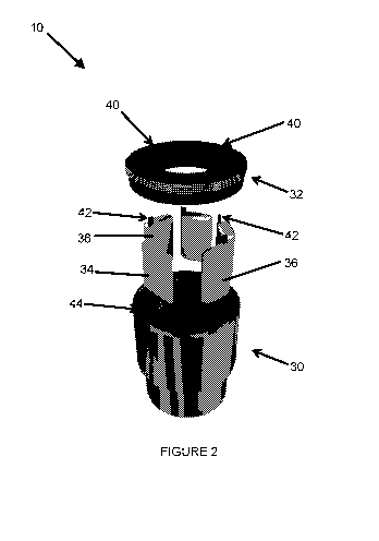
[0054] Figure 2 illustrates an exploded view of a spindle bushing according
to an
embodiment of the invention.
DESCRIPTION OF EMBODIMENTS
[0055] In Figure 1A and 1B, an exploded view (1A) and an assembled view
(1B)
of a commercially available backend assembly for a core drilling tool as used
in the
art is illustrated. Backend assembly 100 comprises a spearhead assembly (12),
a
latching mechanism (14), a landing shoulder (16), a spindle assembly (18) and
inner
tube cap assembly (20). Spindle assembly (18) comprises a measurement device
in
the form of a spindle bushing (10).
[0056] In Figure 2, an exploded view of a measurement device 10 in the form
of a
spindle bushing according to an embodiment of the invention is illustrated.
Measurement device 10 comprises a housing portion (30), a lid portion (32),
data
acquisition portions (36) and a power source (38). Lid portion (32) is screw
threadably engaged with housing portion (30) and comprises apertures (40) for
receiving external antennae (42) associated with a communication portion of
the data
acquisition portions (36). Data acquisition portions (36) and power source
(38) are
positioned in receiving portions (44) located in the body of the housing
portion (30).
[0057] In the present specification and claims (if any), the word
'comprising' and
its derivatives including 'comprises' and 'comprise' include each of the
stated
integers but does not exclude the inclusion of one or more further integers.
[0058] Reference throughout this specification to 'one embodiment' or 'an
embodiment' means that a particular feature, structure, or characteristic
described in
connection with the embodiment is included in at least one embodiment of the
present invention. Thus, the appearance of the phrases 'in one embodiment' or
'in
an embodiment' in various places throughout this specification are not
necessarily all
referring to the same embodiment. Furthermore, the particular features,
structures,
or characteristics may be combined in any suitable manner in one or more
combinations.
CA 03159038 2022-04-26
WO 2021/087558
PCT/AU2020/051196
18
[0059] In compliance with the statute, the invention has been described in
language more or less specific to structural or methodical features. It is to
be
understood that the invention is not limited to specific features shown or
described
since the means herein described comprises preferred forms of putting the
invention
into effect. The invention is, therefore, claimed in any of its forms or
modifications
within the proper scope of the appended claims (if any) appropriately
interpreted by
those skilled in the art.