Note : Les descriptions sont présentées dans la langue officielle dans laquelle elles ont été soumises.
WO 2021/119851
PCT/CA2020/051779
REFUELING TOOL AND SYSTEM INCORPORATING THE REFUELING
TOOL
FIELD
The present disclosure relates to a method, system and tool for safely
accessing, opening and closing fill/drain valves on artificial satellites
during on-
orbit propellant resupply operations. More particularly the tool is designed
for
propellant resupply of satellites not originally prepared for being resupplied
as
well as satellites designed for resupply. The present disclosure is especially
designed to ease the propellant resupply of satellites not originally prepared
for
being resupplied after an initial resupply due to the components left behind
on
the satellite during the initial resupply.
BACKGROUND
Many satellites currently in operation were designed with a finite amount
25 of propellant and were not designed for the possibility of being
resupplied with
propellant. The design philosophy relied upon replacement of the satellites
after
they had exhausted the on-board propellant supply. In view of the expense of
replacing satellites, it would be very advantageous to be able to resupply
satellites with propellant which are either near their end of propellant life
but
otherwise functional, or have suffered an insertion anomaly, or have been
maneuvered more than originally intended for their nominal operations, thereby
extending their operational life by several or many years. It is estimated
that as
many as half of all GEO communication satellites end their 10 to15 year life
with all or most of their subsystems still functional and it is only the
depletion of
the carefully budgeted propellant load that drives retirement of the
satellite.
Using a current economic model, the ability to resupply these end of life
satellites in one mission with propellant, would extend each of their useful
lives
by 3 to 5 years and thereby delay the need to outlay the very high capital
costs
to launch a replacement for each satellite. Some satellites suffer from
primary
propulsion system failures or launch vehicle upper stage related failures soon
after they are launched. In these cases the entire book value must be written
off
and compensation paid to the operator by the insurer. The satellite becomes an
asset of the insurer and will eventually have to be disposed of in a graveyard
or
1
CA 03161013 2022- 6- 7 SUBSTITUTE SHEET (RULE 26)
WO 2021/119851
PCT/CA2020/051779
re-entry orbit. If one of these assets can be resupplied with propellant,
enabling
it to transfer to an orbital station in geosynchronous orbit and extending its
life
by 5 to 10 years, most or all of the value of the spacecraft can be recovered.
In addition, new long duration satellite concepts are being proposed
where a modular satellite consists of an underlying structure supporting power
generation, guidance and control and payload modules, some or all of which
can be exchanged or added to over a lifetime that may be significantly longer
than current satellites. These satellites benefit from not only an initial
resupply
of propellant, but from repeated resupply missions over many years of
1.0 operation.
The key technical difficulty is that these satellites were not designed for
robotic servicing, and it is not generally accepted that such missions are
technically possible. Specifically, most satellites are designed with
propellant fill
and drain valves, (or FDVs), that were intended to be filled once prior to
launch
and never opened or manipulated again. Thus, accessing these FDVs remotely
in-orbit presents several major challenges and would involve several
operations, each of which is difficult to accomplish robotically including:
cutting
and removal of the protective thermal blankets, removal of several lockwires
hand wrapped around the valves, unthreading and removing outer and inner
valve caps, mating a fuel fill line to the valve nipple, mechanically
actuating the
valve, and when resupply with propellant is complete, replacing the inner
valve
cap. On-orbit servicing has been the subject of much study over the past
thirty
years. The idea of maintaining space assets rather than disposing of and
replacing them has attracted a variety of ideas and programs. So far the
concept has only found a home in the manned space program where some
success can be attributed to the Solar Max and Hubble Space Telescope repair
missions, Palapa-B2 and Westar rescue missions and the assembly and
maintenance of the International Space Station.
Robotic capture and servicing of operating geostationary spacecraft has
never been demonstrated. Until recently there have been no technologies
disclosed that can solve the problem of accessing the propellant system of an
unprepared satellite for the purpose of replenishing station keeping
propellant.
2
CA 03161013 2022- 6-7
WO 2021/119851
PCT/CA2020/051779
The majority of artificial satellites in orbit today were not designed with
orbital
propellant resupply in mind and access to the propellant system is designed to
be accessed by a human on earth before launch. The technologies required to
access the client spacecraft's propellant system for the purposes of resupply
of
propellant still have a very low technology readiness level, and are generally
considered to be the main obstacle to a successful servicing mission.
Transferring fuels used for spacecraft propulsion systems from one
source to another is very dangerous, due to the corrosive and explosive nature
of the liquids involved. For example, inadvertent mixing of fuel and oxidizer
in
bipropellant systems will cause immediate combustion, so a liquid transfer
system for bipropellant-based fuels needs to ensure that no accidental mixing
occurs. It would be very advantageous to provide a system of tools that are
designed for opening and closing of a variety of types/sizes of satellite FDVs
during a propellant resupply operation being conducted on an unprepared
satellite, such as but not limited to, removal of the sealing cap assembly,
coupling/decoupling of propellant hoses to the client satellite, installation
of a
new sealing cap assembly to mention just a few.
The FDVs on existent satellites come in several designs, of varying
dimensions and operating concepts. Therefore, to maximise the economic
benefit of such a propellant resupply system, the minimum number of tools of
minimum mass should be carried on any mission to permit the resupply of the
widest selection of FDV designs using a single tool. Further mass and
operational advantages accrue if various aspects of the refueling tool
function
can be evaluated and controlled using visual means as opposed to relying upon
a host of limited sensors.
A further advantage can be realised if the resupply system can be
engaged successfully with the broadest possible arrangement of FDVs on the
satellite to be resupplied, this being exemplified by being able to
accommodate
the smallest possible spacing between FDVs.
United States Patent No. 8,074,935 B2 issued to Gryniewski et al. issued
December 13, 2011, discloses a system and method for refueling unprepared
satellites from a servicing spacecraft which includes a robotic arm, suitable
3
CA 03161013 2022- 6-7
WO 2021/119851
PCT/CA2020/051779
tools which can be affixed to the end effector of the robotic arm required for
accessing, opening and closing the fuel fill valve on the satellite being
serviced,
storage and retrieval stations on a tool caddy on which the tools and various
fuel fill valve caps are stored. Several discreet sockets are included for the
different sized components making up the fill drain valve that must be removed
prior to the refueling operation and returned post refueling. During
engagement
with the removable features of the fill drain valve (FDV) the sockets cover
the
entire part being removed. In addition, this refueling tool could not
accommodate the variation of vertical/longitudinal axis position of the
removable or actuatable features on the variety of fill drain valves to be
serviced.
United States Patent No. 9,567,111 issued to Roberts et al. discloses a
system and tool for accessing fill/drain valves during propellant resupply of
a
client satellite by a servicer satellite. This apparatus uses two to three cam
wrenches which fit down over the FDV with one wrench engaging unmovable
flats and the other engaging rotatable features of the removable valve
components. Advantages of this system is that it provides intrinsic torque
balancing via the use of a differential gearbox. The wrenches are also
configured to be able to accommodate a range of torque feature sizes and
shapes (reaction flats, hex, round with flats, square) and is designed with a
2x
torque margin.
Disadvantages of both systems above is there is no sensing of the tool
states or valve states due to the valve and tools being generally obscured.
The
cam wrenches of the latter system work as two opposing pairs operating at two
elevations on features of different size, each relying on a complex hinging
engagement that is triggered by rotating contact of the cams as they close
towards the valve body at the base and the actuation nut higher up. The
engagement of both pairs of cam wrenches can only occur simultaneously, as
they are driven in opposing directions via a differential that can only
generate
torque through one pair of cam wrenches acting against the other. The
strength of this approach is the ability to accommodate a range of sizes and a
range of shapes, as well as intrinsic torque balancing, however this also
makes
it impossible to determine exactly when or if engagement has begun to occur,
4
CA 03161013 2022- 6-7
WO 2021/119851
PCT/CA2020/051779
hence it is impossible to determine the exact state of FDV features. New
information from one FDV supplier indicated excessive rotation of the
actuation
nut in the opening direction could result in a failure of the actuation nut
retention
feature and subsequently the unintended removal of the actuation nut and the
generation of uncaptured debris. Consequently a new requirement was
generated for a maximum rotation of the actuation nut, not to be exceeded.
This leads directly to a need for enhanced sensing of the valve states.
SUMMARY
io Disclosed herein is a system and a device which facilitates on-orbit
refueling by teleoperation of FDVs of various designs and dimensions on
satellites not originally prepared for on-orbit servicing, through the
installation of
quick connect safety valves, using vision-based and sensor-based feedback to
operate a suite of adaptable and adjustable mechanisms.
There is provided a method of transferring fluid from a servicer
spacecraft to a client spacecraft, the client spacecraft including a tank and
a fill
drain valve coupled to the tank, the fill drain valve including a valve
actuation
nut for opening and closing the fill drain valve, the fluid being selected
from the
group consisting of fuel and oxidizer, the method comprising instructing a
robotic arm on the servicer spacecraft to perform the steps of:
a. removing an access valve cap on the fill drain valve;
b. providing a sensed confirmation that the removal action has
successfully occurred;
c. establishing a fluid connection between a safety valve and a source
of propellant on the servicer spacecraft;
d. providing a sensed confirmation that the connection has been
established;
e. attaching the safety valve to the fill drain valve to provide a safe fluid
coupling permitting fluid flow into but not out of the fill drain valve;
f. providing a sensed confirmation that the safety valve has been
installed;
5
CA 03161013 2022- 6-7
WO 2021/119851
PCT/CA2020/051779
g. opening the fill drain valve by actuating the valve actuation nut;
h. providing sensed confirmation that the actuation nut has been
actuated, and
i. transferring fluid into the tank through the safety valve.
The steps b), d), f) and h) of providing a sensed confirmation may be
accomplished using a combination of feedback provided by real-time visual
images and feedback from sensors strategically located, to observe and to
sense positions of the access valve cap, the safety valve, the fluid line, the
fill
drain valve and valve actuation nut.
method of refueling a client satellite by accessing one or more fill drain
valves which are in flow communication with one or more propellant storage
tanks located in the client satellite, the method of refueling being conduced
using a servicer spacecraft having stowed thereon
a) one or more safety valves;
b) a refueling tool having refueling tool vision system which
includes at least one camera, a rotatable wrench portion, an open
architecture structure such that when the refueling tool is engaged with a
fill/drain valve, a field of view of the camera encompasses the fill/drain
valve being engaged and the rotatable wrench of the refueling tool and a
coupling nut of a safety valve installed on the fill/drain valve, including
strategically placed sensors on selected movable components of the
refueling tool in order to sense a position of the selected movable
components during the refueling operation,
c) a suite of supporting tools for preparing the client satellite to
receive the refueling tool and assisting in the refueling operation,
the servicer spacecraft having mounted thereon
a) a robotic arm mounted to the servicer spacecraft at its proximal
end,
b) a berthing device for rigidly connecting the client satellite to the
servicer spaceship,
6
CA 03161013 2022- 6-7
WO 2021/119851
PCT/CA2020/051779
c) a propellant transfer system for transferring propellant from the
servicer spacecraft to the client satellite, and
d) a propellant coupling mounted in the end effector coupled to the
propellant transfer system for transferring propellant to the client
satellite through the propellant coupling,
the method of refueling comprising the steps of:
a) maneuvering the servicer satellite into close proximity with the client
satellite and rigidly berthing the client satellite to the servicer satellite
using berthing device,
io b) exposing the fill/drain valve by instructing the robotic arm to
acquire
in a sequential manner the tool and the supporting tools to loosen
and remove any objects covering the fill/drain valve, and once a
given object is removed stowing the tool,
C) after the fill drain valve is exposed, instructing the robotic arm to
acquire the refuelling tool which is configured such that a fluid
connection between the safety valve and propellant tank on the
servicer spacecraft is established,
and once acquired, instructing the robotic arm to acquire a safety
valve thereby connecting the propellant transfer system to the safety
valve,
d) instructing the robotic arm to install the safety valve on a refueling
nipple of the fill drain valve based on real-time visual images obtained
by the refueling tool vision system and feedback from one or more of
sensors,
e) transfer propellant to the client satellite with the propellant passing
through the tool and safety valve,
f) once propellant has been transferred, instructing the robotic arm to
disconnect the propellant transfer system by disconnecting the
refuelling tool from the fill/drain valve, and
g) disengage the berthing deviced from the client satellite.
7
CA 03161013 2022- 6-7
WO 2021/119851
PCT/CA2020/051779
The method may include logging an output of the one more sensors. The
sensors may be one or more microswitches, and one or more potentiometers,
or any combination thereof.
The sensors may be microswitches, and wherein the feedback from one
or more of microswitches is the status of the microswitch at that particular
time
during the refueling operation.
The microswitches may be placed within a mechanism tasked with
installing the safety valve on the fill/drain valve to sense the safety valve
during
acquisition and to sense a safety valve coupling nut of the safety valve
contacting the refueling nipple of the fill/drain valve during refueling
operation.
The present disclosure provides a system mounted on a servicing
spacecraft for transferring fluid to a client satellite, the client satellite
including a
tank and a fill drain valve, the tank being coupled to the fill drain valve,
the fill
drain valve having an actuation nut for opening and closing the fill drain
valve
and an access valve cap on the fluid fill drain valve, comprising:
a. fluid transfer means for transferring a fluid from a fluid tank on the
servicing spacecraft to the tank on the client satellite, wherein the fluid
is selected from the group consisting of fuel and oxidizer;
b. tool means for removing and replacing the access valve cap, for
coupling a fluid line to the fill drain valve and decoupling therefrom, and
for actuating the valve actuation nut to open and close the fluid valve;
c. a first sensing means for determining a relative displacement between
the tool means and the fill drain valve;
d. a second sensing means for determining the state of the fill drain valve
during the successive steps of accessing and manipulating the fill drain
valve and subsequently coupling a fluid line and decoupling therefrom;
e. a safety valve attachable to the fill/drain valve for providing a safe
fluid
coupling with the safety valve having one or more independent seals
against leakage during and after refueling;
f. positioning means connectable to the tools means, for positioning the
tool means with respect to the fill drain valve; and
g. control means in communication with the first and second sensing
8
CA 03161013 2022- 6-7
WO 2021/119851
PCT/CA2020/051779
means, the positioning means, and the tool means, for controlling
operation of the positioning means and the tool means based on
feedback from the first and second sensing means.
The tool means may include
a first tool for loosening the access valve cap, actuating the valve
actuation nut to open and close and coupling a fluid line to the fill drain
valve and decoupling therefrom, and
a second tool for removing the access valve cap.
The tool means may include a third tool for removing a crush seal from
the fill drain valve.
The first sensing means may be a vision system positioned to have a
field of view to observe the relative displacement between the tool means and
the fill drain valve.
The second sensing means is a combination of
a vision system positioned to have a field of view that
encompasses a work space that includes the first and second tools
engaging the fill drain valve, and
sensing means embedded in the tool means that sense and log a
position of selected movable components during fluid transfer
operations.
The present disclosure provides a refueling tool mounted on a servicer
spacecraft for opening and closing one or more fill/drain valves on a client
satellite to be refueled with the one or more fill/drain valves being in flow
communication with a fuel tank on the client satellite, the one or more
fill/drain
valves having rotatable and static features coaxially aligned along a first
axis,
the servicer spacecraft including stowed safety valves to be installed on the
fill/drain valves during refueling prior to passing fuel through the safety
valve
and fill/drain valves, and further including a refueling system configured to
be
mated to the safety valve during refueling operations, comprising:
a refueling tool structure including
a) a mechanism A for registering to and clamping onto the fill drain valve
body and torque reaction flats of a target fill drain valve;
9
CA 03161013 2022- 6-7
WO 2021/119851
PCT/CA2020/051779
a rotatable wrench comprising
a mechanism B1 for closing and opening of the rotatable wrench;
a mechanism B2 for rotation of the wrench, mechanism B1 for closing
and opening the wrench being compliantly mounted to the mechanism B2;
a mechanism C for elevation adjustment of the rotatable wrench;
the mechanism B2 being mounted to mechanism C, with the
mechanisms A, B1, B2 and C forming a substructure that forms a torque
reaction loop that ensures that torque induced by rotating the rotatable
wrench
is reacted at the valve body via the torque reaction flats, as required;
b) a mechanism D for connection of the refueling system to a refueling
nipple of the target fill drain valve being engaged, the mechanism D being
connected to the substructure and to a top plate connected to the substructure
by side plates to form a complete refueling tool structure;
an end effector interface connected to the top plate and configured to be
grasped and mated to a robotic end effector mounted to a robotic arm mounted
on the servicer spacecraft;
one or more sensors placed within mechanism D, to sense the safety
valve during acquisition and to sense safety valve coupling nut of the safety
valve contacting the refueling nipple of the fill/drain valve during refueling
operations; and
a tool vision system which includes at least one camera attached to the
refueling tool structure, the substructure having an open architecture such
that
when the refueling tool is engaged with a fill/drain valve, a field of view of
the at
least one camera encompasses the fill/drain valve being engaged and the
rotatable wrench of the refueling tool and a coupling nut of the safety valve
such that during the refueling operation, wherein all states of the rotatable
wrench and the fill/drain valve and the safety valve can be sensed and/or
observed using a combination of a status of a status of the microswitches and
real-time images from the at least one camera.
CA 03161013 2022- 6-7
WO 2021/119851
PCT/CA2020/051779
The sensors may be microswitches, and wherein the feedback from one
or more of microswitches is the status of the microswitch at that particular
time
during the refueling operation.
The sensors may be one or more microswitches, and one or more
potentiometers, or any combination thereof.
The present disclosure provides a system for refueling a client satellite,
comprising:
a) a servicer spaceship having mounted thereon:
a robotic arm mounted to the servicer spacecraft at its proximal
end, an end effector mounted to a distal end of the robotic arm,
a berthing device for rigidly berthing the client satellite to the
servicer spaceship,
a propellant transfer system,
propellant coupling mounted in the end effector coupled to the
propellant transfer system for transferring propellant to the client satellite
through the propellant coupling,
a control system in communication with the robotic arm, the end
effector, the propellant transfer system and the refueling tool for
controlling the refueling operation based on feedback from the sensor
system and the at least one camera;
a communication system for remote communication with the
servicer spacecraft,
b) the servicer spaceship having stowed thereon:
the refueling tool
one or more safety valves to be installed on the fill/drain valves
during refueling prior to passing fuel through the safety valve and
fill/drain valves, the propellant coupling being configured to be mated to
the one or more safety valves, the one or more safety valves being
configured to be picked up by, and mated to, the end effector;
11
CA 03161013 2022- 6-7
WO 2021/119851
PCT/CA2020/051779
a suite of site preparation tools configured to be picked up by, and
mated to, the end effector, the site preparation tools configured to
perform selected tasks to prepare the client satellite to receive the
refueling tool; and
a suite of refueling support tools configured to be picked up by,
and mated to, the end effector, the refueling support tools configured to
engage the fill/drain valves to prepare them to receive the safety valve.
The present disclosure provides a suite of supporting tools for preparing
a client satellite to be refueled, comprising:
a suite of tools each having a specific function, each tool having a drive
shaft and tool section configured for its specific function;
a common tool base to which each of the suite of tool tips are
permanently attached, the common tool base including
a housing with a grasping interface on one side thereof configured
for robotic grasping by an end effector attached to a distal end of a
robotic arm mounted on a servicing satellite, the grasping interface
including a grapple fixture, the other side of the housing configured to
have a tool attached thereto and to receive the driveshaft of the tool;
two tool mechanism drive interfaces used for enacting functions of
a given tool tip via a drive actuator mechanism that is located in the end
effector of the robotic arm, one of the two tool mechanism drive
interfaces being used to drive specific tool tip on each of the support
tools, and the second being use to drive a tie-down stowage mechanism
for retaining the common base when not grasped by the robotic arm,
a tool mechanism gear train located in the housing that transfers
rotation and torque from one of the tool mechanism drive input interfaces
to the tool driveshaft via the tool mechanism gear train interface, for
actuation of tool function.
a tie-down mechanism 'active-half, coupled to, and driven by the
second tool mechanism drive interface for use when retaining the
common base in the tie-down mechanism when it is not being used and
is demated from the end effector.
12
CA 03161013 2022- 6-7
WO 2021/119851
PCT/CA2020/051779
The tie-down mechanism comprises a receptacle housing secured to the
servicing spacecraft having a passive locking mechanism configured to receive
the tool retained in the common base and to engage with, and lock, the tie-
down mechanism 'active-half of the common base.
The common base and the receptacle housing include visual cues to
visually assist the robotic arm aligning the common base with the receptacle
housing during operations to insert and lock the common base in the receptacle
housing.
The suite of supporting tools may include site preparation tools each of
which include a common base and a tool tip attached thereto with each tool tip
including a specific device action, the tool tip common structure includes a
housing with an interface configured to be bolted to the common base, an
internally threaded drive shaft having a portion extending out of the housing
which is inserted into the common base to engage one of the two mechanism
drive interfaces, an advancing externally threaded rod which is threadably
installed in the a portion of the drive shaft located inside the housing, a
set of
input linkages and a set of output linkages located at the distal end of the
common structure, wherein rotation of the drive shaft causes the linear
movement of the advancing threaded rod which in turn moves a set of input
linkages which in turn cause pivotally connected output linkages forming part
of
the device action features to pivot about a specific point in the given tool
tip
causing the device action features to open or close, depending on the
direction
of motion.
The supporting tool may be a thermal blanket scissor device, such that
the device action features are a pair of cutting shears integrally formed with
distal ends of the output pivotally connected output linkages to provide
cutting
action.
The supporting tool may be a thermal blanket handling device, such that
the device action features are a pair of blanket paddles integrally formed
with
distal ends of the output pivotally connected output linkages to provide a
gripping action for gripping and removing pieces of thermal blanket.
The supporting tool may be a wire cutter and gripping tool, such that the
device action features are a pair of wire cutter shears with wiring gripping
13
CA 03161013 2022- 6-7
WO 2021/119851
PCT/CA2020/051779
features integrally formed with distal ends of the output pivotally connected
output linkages to provide a gripping action for gripping and cutting wires.
The suite of supporting tools may include a crush seal removal tool for
removing crushed seals produced when the fill/drain valve B-nut is removed,
the crush seal removal tool including the common base and attached thereto a
crush seal removal tool tip which includes an interface configured to be
bolted
to the common base, an internally threaded rotatable drive shaft which has a
portion which is inserted into the common base to engage one of the two
mechanism drive interfaces, an externally threaded plunger partially into the
internally threaded drive shaft and reciprocally moveable therein, the plunger
having a distal plunger face, including a pair of flex jaw linkages pivotally
connected together a pivot point, the flex jaw linkages each having a distal
flex
jaw tip, the flex jaw linkages extending through openings in cage which is
rigidly
mounted on tool tip base structure, wherein when the drive shaft is rotated,
plunger translates backwards into the drive shaft and while the plunger
translates, the pivot point of the flex jaw linkages moves with the plunger
causing the flex jaw tips to close and retract making contact with a valve
stem
of the fill/drain valve and dragging along the fill/drain valve stem, the flex
jaw
tips become preloaded against the fill/drain valve stem and dragged along
until
they hook onto the crush seal and pry it loose where it is trapped in the cage
between the flex jaw tips and the distal plunger face, and wherein rotation of
the
drive shaft in the reverse direction opens the flex jaw tips and ejects the
crush
seal from the tool tip by pushing the plunger face forward and pushing the
crush
seal out of the cage.
The suite of supporting tools may include a B-nut removal tool, the B-nut
removal tool including the common base and permanently attached thereto a B-
nut removal tool tip, the B-nut removal tool tip including a tool tip base
structure
which is permanently attached to the common base, a drive shaft having a
portion which is inserted into the common base to engage one of the two
mechanism drive interfaces, spring wrench fingers coupled to a distal end of
the
drive shaft, a collet, having a keyed connection to the spring wrench fingers
at
the proximal end of the spring fingers allowing only motion along the axis of
rotation of the drive shaft, the collet having a slots in the outer diameter
of the
14
CA 03161013 2022- 6-7
WO 2021/119851
PCT/CA2020/051779
collet, enclosed in a pin carrier housing, including cam-pins mounted in the
pin
carrier housing that run in the slots, and the pin carrier housing delayed
from
rotation by the ratchet disc via preloaded against the pin carrier housing at
the
ratchet disc interface by the preload spring, where rotation of the ratchet
disc is
restricted by the key feature between the ratchet disc and the tip base
structure,
so that in order for the pin carrier housing to rotate with the drive shaft
the collet
must move axially forward as driven by the cam-pins in the pin slots until the
end of the pin slots forcing the collet to close the spring fingers over the B-
Nut
against the B-Nut hex features and continued drive shaft rotation causing
rotation of the pin carrier housing, with the collet enclosing the spring
fingers
and B-Nut, as the ratchet disc interface preload spring preload force is
overcome and allows the pin carrier housing surface with ramp features to
repeatedly slide over the ratchet disc surface with ramp features thus
unthreading the B-Nut from the FDV and such that reversing the drive shaft
rotation retracts the collet and allows the spring fingers to open so that the
B-
Nut is no longer contained and is able to be discarded.
BRIEF DESCRIPTION OF THE DRAWINGS
Embodiments of the mechanism for teleoperation of satellite FDVs will
now be described, by way of example only, with reference to the drawings, in
which:
FIGURE 1 shows a typical arrangement of FDVs 54 on FDV bracket 52,
including a section view in FIGURE 1A through the lower body 56 of the FDVs
in the region which includes torque reaction flats 58, the region being the
region
where registration of the FDV occurs via mechanism A 12.
FIGURE 1B shows a side view of the FDVs 54
FIGURE 1C shows individual features of the FDV.
FIGURE 1D shows the components which cap the valve.
FIGURES 2 and 2A are perspective views of the refueling tool 10
aligned and registered with an FDV 54, in preparation for refueling.
FIGURE 3A is a perspective view of mechanism A 12.
CA 03161013 2022- 6-7
WO 2021/119851
PCT/CA2020/051779
FIGURE 3B is a view of the underside partially sectioned to show the
arrangement of jaws 121, rollers 123 and grippers 125.
FIGURE 4A, 4B and 4C are shows section views of mechanism A 12,
including the tension assembly 113 and drive link 116, rocker 117 and
connecting links 118.
FIGURES 5A through 5E collectively demonstrate the adaptability of
mechanism A 12.
FIGURE 5A is a sequence of images showing the self-centring
behaviour inherent in mechanism A wherein the initially large lateral offset
is
corrected before final seating of contact fingers 126 on valve body 32 and
torque reaction flats 34.
FIGURES 5B and 5C show the closed configuration on a small valve
body 32 in both the parallel and perpendicular orientations.
FIGURES 5D and 5E show the closed configuration on a large valve
body 32.
FIGURES 5F and 5G show the closed configuration on a still larger valve
body in both the parallel and perpendicular configurations.
FIGURES GA and GB are perspective views of mechanism B1 14.
FIGURE 6C is an exploded view showing details of the B1 actuator mounting
arrangement.
FIGURE 7A is an orthographic view of mechanism B1 14.
FIGURE 7B is a folded section through all rotation centres.
FIGURES. 8A, 8B and 8C are section views of mechanism B1 showing
the spring plungers related to the auto-stop feature of wrench closing.
FIGURE 8D shows the gear train of mechanism B1.
FIGURES 9A and 9B are perspective views of compliance mechanism
16, the latter including the relationship to mechanism B1 14.
FIGURES 10A, 10B and 10C are orthographic views of compliance
mechanism 16.
16
CA 03161013 2022- 6-7
WO 2021/119851
PCT/CA2020/051779
FIGURES 11A and 11B are perspective views of mechanism B2 18, the
latter including the relationship to compliance mechanism 16.
FIGURES 12A and 12B are orthographic views of mechanism B2 18.
FIGURES 12C and 12D are section views of mechanism B2 18.
FIGURES 13A and 13B shows mechanism B2 18 with compliance
mechanism 16 and mechanism B1 14 at clockwise and counter-clockwise
travel limits.
FIGURES 14A and 14B are perspective views of mechanism C 20, the
latter including the relationship to mechanism B2 18.
FIGURE 15 shows a different perspective view of mechanism C 20
depicting the region where mechanism A 12 attaches to mechanism C 20.
FIGURE 16A shows the safety valve.
FIGURE 16B shows conceptually the safety valve internal components.
FIGURE 17 shows perspective views of mechanism D 22.
FIGURE 18 shows a different perspective view of mechanism D 22
including the relationship to mechanism C 20.
FIGURES 19 and 20 are exploded views of mechanism D 22.
FIGURE 21 is an exploded view of transmission 26.
FIGURE 22 is a top view of transmission 26, with FIGURE 22B showing
a section through the input gear stack.
FIGURES 23A through 23D show each of the four (4) layers of gears
within transmission 26.
FIGURE 24 is a section view of refueling tool 10 beneath top plate 479.
FIGURE 25 is a top view of refueling tool 10, with a breakout section
revealing transfer gears 508 for first rotary input shaft 502.
3.7
RECTIFIED SHEET (RULE 9 1 . 1)
CA 03161013 2022- 6-7
WO 2021/119851
PCT/CA2020/051779
FIGURE 26 is a section view of transmission 26 revealing the input
gears 454 and quill shaft 509, with a further breakout section showing
transmission lead screw 484.
FIGURE 27 shows a concept for robotic end effector suitably equipped
for executing all of the servicing tasks described herein.
FIGURES 28 TO 36 show perspective and cross-sectional views of
various independent support tools used by the servicer spacecraft to prepare
the client satellite for refueling.
FIGURES 37 to 39 show in the left-hand panel of each FIGURE a
io perspective view, and in the right-hand panel of each FIGURE cross
sectional
view of three (3) site preparation tool tips including a blanket cutter tool
650 in
FIGURE 37, a blanket handler tool 652 in FIGURE 38 and a wire cutter tool 654
in FIGURE 39.
FIGURE 40 shows perspective views of a B-Nut removal tool tip used for
removing the FDV B-nut prior to refueling, with the left-hand panel showing
the
tool fully assembled and the right-hand panel showing the tool partially
disassembled to show some of the internal components.
FIGURE 41 shows a partial perspective view in the left-hand panel and a
full cross-sectional view taken from the perspective view of the -Nut removal
tool tip prior to engagement with the FDV.
FIGURES 42 to 45 show a partial perspective view in the left-hand panel
and a full cross-sectional view taken from the perspective view B-Nut removal
tool 608 during stages of motion once it has engaged with the B-nut on the
FDV.
FIGURE 46 is a perspective view of a crush seal removal tool tip 700 for
removal of the crush seal.
FIGURES 47 to 50 show various elevational views (top panels) of the
crush seal removal tool tip 700 and associated cross sectional views (bottom
panels) taken along the cross-section lines.
18
CA 03161013 2022- 6-7
WO 2021/119851
PCT/CA2020/051779
FIGURE 51 is a perspective view of an embodiment of a tool tie-down
mechanism located above its associated tool tie-down receptacle.
FIGURES 52 and 53 are cross sectional views from FIGURE 51 of the
tool tie-down mechanism.
FIGURE 54 is a system diagram showing a servicer satellite berthed to a
client satellite to be refueled, showing the various supporting tools needed
for
accessing the FDV sequestered on the servicer satellite.
FIGURE 55 shows a non-limiting exemplary example of a computer control
system that may be used to control the actions of the robotic tool.
io FIGURE 56 is a block flow chart that describes in detail the steps
taken
by the servicer spacecraft 80 when it is engaged with the client satellite 81
during refueling operations.
DETAILED DESCRIPTION
Various embodiments and aspects of the disclosure will be described
with reference to details discussed below. The following description and
drawings are illustrative of the disclosure and are not to be construed as
limiting
the disclosure. The drawings are not necessarily to scale. Numerous specific
details are described to provide a thorough understanding of various
embodiments of the present disclosure. However, in certain instances, well-
known or conventional details are not described in order to provide a concise
discussion of embodiments of the present disclosure.
As used herein, the terms, "comprises" and "comprising" are to be
construed as being inclusive and open ended, and not exclusive. Specifically,
when used in this specification including claims, the terms, "comprises" and
"comprising" and variations thereof mean the specified features, steps or
components are included. These terms are not to be interpreted to exclude the
presence of other features, steps or components.
19
CA 03161013 2022- 6-7
WO 2021/119851
PCT/CA2020/051779
As used herein, the term "exemplary" means "serving as an example,
instance, or illustration," and should not be construed as preferred or
advantageous over other configurations disclosed herein.
As used herein, the terms "about" and "approximately", when used in
conjunction with ranges of dimensions of particles, compositions of mixtures
or
other physical properties or characteristics, are meant to cover slight
variations
that may exist in the upper and lower limits of the ranges of dimensions so as
to
not exclude embodiments where on average most of the dimensions are
satisfied but where statistically dimensions may exist outside this region. It
is
not the intention to exclude embodiments such as these from the present
disclosure.
Embodiments of the refueling tool comprise the following components in
reference to the Figures.
Parts List
10 -refueling tool
12 - mechanism A, centre and clamp
14 - mechanism B1, wrench closing/opening
16 - compliance mechanism
18 - mechanism B2, wrench rotation
20 - mechanism C, wrench elevation
22 - mechanism D, FDV connection
26 - transmission
40 - refueling tool vision system-based architecture
42 - camera
44 - camera bracket
46 - camera shield
50 - FDV worksite
CA 03161013 2022- 6-7
WO 2021/119851
PCT/CA2020/051779
52 - FDV bracket
54 - fill/drain valve, FDV
56 - valve body
58 - torque reaction flats
60 - FDV axis
62 - FDV actuation nut
64 - B-nut
66 - FDV flange
68 - FDV welded connection
70 - FDV nipple
80 - servicer spacecraft
81 - client
82 - stowage post
83 - safety valve fixture
84 - robotic arm
102 - mechanism "A" input shaft
103 - thrust ball bearing
104 - thrust needle roller bearing
105 - tension housing
106 - lead nut
107 -piston
108 -cross pin
109 -springs
110 -spacer
21
CA 03161013 2022- 6-7
WO 2021/119851
PCT/CA2020/051779
111 -spacer
112 - end cap
113 - tension assembly
114 - linear bearing rail
115 - linear bearing block
116 - drive link
117 - rocker arm
118 - connection links
119 - push rod
120 -bushing
121 -jaw
122 -pivot
123 -roller
124 - roller bracket
125 - gripper
126 - contact finger
127 - microswitch
128 - mechanism "A" frame
129 - mechanism A mounting interface
150 - B1 lead screw
151 - lead screw drive gear
152 - B1 housing
153 - B1 cover
154 -wrench jaw
22
CA 03161013 2022- 6-7
WO 2021/119851
PCT/CA2020/051779
155 - lead nut
156 - nut clamp
157 - locking pin
158 - idler gear
159 - B1 drive input gear
160 - B1 drive actuator
161 - B1 actuator adaptor
162 - B1 housing actuator recess
163 - retaining clip
164 - actuator adaptor pin
165 - plunger guide
166 - plunger spring
167 -plunger
168 - plunger bifurcated head
169 - microswitch
170 - B1 mounting lugs
171 - shoulder bolts
172 -bearing
173 - idler shaft
174 - idler bearing
175 - torque reacting recess
176 - torque reacting shaft
200 - torque cell plate
201 - torque cell
23
CA 03161013 2022- 6-7
WO 2021/119851
PCT/CA2020/051779
202 - coupling bracket
203 - down-swept protrusion
204 - coupling platform
205 - protruding lug
206 - ball bushing
207 - bushing circlip
208 - first pair of precision shafts
209 - second pair of precision shafts
210 - length-adjustable locking shaft collar
211 - compression spring
212 - compliance mechanism mounting interface
250 - rotation track plate
251 - B2 drive gear
252 - internally splined hub
253 - B2 drive housing
254 - bearing
255 - thrust pad
256 - segment gear assembly
257 - segment gear
258 - segment gear carrier
259 - first pair of track rollers
260 - end-of-travel pin
261 - tensioner assembly
262 - tensioner yoke
24
CA 03161013 2022- 6-7
WO 2021/119851
PCT/CA2020/051779
263 - second pair of track rollers
264 - tensioning screw
265 - disc spring
266 - microswitch
267 - microswitch spacer
268 - precision rolling surfaces
269 - segment gear bumper
270 - wrench rotation axis
271 - elevation travel indicator
272 - interface to mechanism A
300 - refueling tool back plate
301 - refueling tool mid plate
303 - linear bearing rail
304 - linear bearing block
305 - right angle bracket
306 - non-metallic bumper
307 - retracted microswitch
308 - bearing
309 - mechanism B2 spline shaft
310 - mechanism C lead screw
311 - extended microswitch
350 - safety valve assembly
351 - safety valve body
352 - external locking groove
CA 03161013 2022- 6-7
WO 2021/119851
PCT/CA2020/051779
353 - coupling nut
354 - spring
355 - quick connect nipple
356 - check valve
357 - safety valve shoulder
360 - mechanism D base plate
361 - hose bracket
362 - first set of linear guide rails
363 - adjustable end stop
364 - dual microswitch assemblies
365 -flexible hose
367 - safety valve carriage assembly
368 - safety valve carriage
369 - linear guide block
370 - locking arm post
371 - flanged bushing
372 - locking arm
373 - actuation slot
374 - safety valve sensor assembly
375 - compliant coupling assembly
376 - first actuation actuator
377 - microswitch striker
378 - second set of linear guide rails
380 - mate/de-mate carriage assembly
26
CA 03161013 2022- 6-7
WO 2021/119851
PCT/CA2020/051779
381 - mate/de-mate carriage
382 - linear guide block
383 - track roller
384 - lead nut
385 - quick connect coupling
386 - propellant manifold
387 - dual microswitch assembly
388 - travel stop
390 - splined input shaft
391 - drive bracket
392 - gear
393 - bearing
394 - safety valve lead screw
395 - lead nut
396 - guide housing
397 - guide pin
398 - connecting pin
400 - compliance housing
401 - compliance base
402 - shuttle
403 - spring
405 - sensor housing
406 - sensor base
407 - trigger plate
27
CA 03161013 2022- 6-7
WO 2021/119851
PCT/CA2020/051779
408 - ready-to-latch microswitch
409 - spring
410 - limiting pin
415 - compliance microswitch
416 -compliance striker
417 - advance microswitch
418 - retract microswitch
450 - transmission housing
451 - top cover
452 - bottom cover
453 - gears
454 - input gear
455 - input gear common axis
456 - output gear
457 - internally splined hub
458 - bearing
459 - support housing
460 - thrust washer
461 - complete rim
462 - partial rim
463 - cylindrical groove
464 - housing bore
465 - locating pin hole
466 - locating pin
28
CA 03161013 2022- 6-7
WO 2021/119851
PCT/CA2020/051779
467 - transmission housing mounting interface
470 - transmission bracket
471 - linear guide rail
472 - linear guide block
473 - transmission support plate
474 - lead nut
475 - nut clamp
476 - linear potentiometer
477 - potentiometer mounts
478 - potentiometer rod bracket
479 - refueling tool top plate
480 - transmission lead screw
481 - bearing
482 - bearing retainer
483 - refueling tool side plate
484 - transmission lead screw
485 - transmission range of motion
490 - contact sphere
491 - touchdown rod
492 - touchdown arm
493 - touchdown bracket
500 - refueling tool end effector interface
501 -grasp fixture
502 - first rotary input shaft
29
CA 03161013 2022- 6-7
WO 2021/119851
PCT/CA2020/051779
503 - second rotary input shaft
504 - electrical connectors
505 - quick connect nipple
506 -target
507 - first rotary input gear
508 - transfer gear
509 - quill shaft
510 -bearing
511 -retainer
512 - quill shaft external splines
513 - fuel channel
514 - quill shaft drive gear
515 - transfer housing
516 -grapple fixture probe
550 - dexterous end effector, DEE
551 - capture mechanism
552 - first rotary input socket
553 - second rotary input socket
554 - movable electrical connectors
555 - movable quick connect propellant coupling
556 - end effector camera
601 - Servicing Support Tool, Generic
603 -common tool base
605 -blanket cutter tool
CA 03161013 2022- 6-7
WO 2021/119851
PCT/CA2020/051779
606 -blanket handling tool
607 -wire Cutter Tool
608 -B-Nut Removal Tool
609 -crush seal removal tool
610 -grapple fixture
612 -tool mechanism drive interface ¨ primary
613 -tool mechanism drive interface - secondary
614 -tool mechanism gear train
618 -tie-down mechanism active half
620 -common tool base structure
630 -generic tool tip embodiment
632 tool mechanism gear train interface
634 -tool tip drive shaft
636 -tool tip common structure
638 -tool base to tool tip bolted interface
640 -advancing threaded rod
642 -input linkages
644 -output linkages
645 -cutting shears
646 -gripping paddles
647 -wire cutter shears and wiring gripping features
650 -blanket cutter tool tip
652 -blanket handler tool tip
654 -wire cutter tool tip
31
CA 03161013 2022- 6-7
WO 2021/119851
PCT/CA2020/051779
660 -B-Nut Removal Tool Tip
662 -collet
664 -drive shaft
666 -cam-pins
668 -slots for cam pins
670 -spring wrench fingers
672 -b-nut hex nut feature
674 -ratchet disc interface
676 -pin carrier housing
678 -ratchet disc
680 -tool tip base structure
682 -key feature
684 -preload spring
686 -ratchet disc surface with ramp features
688 -pin carrier housing surface with ramp features
700 -crush seal removal tool tip
702 -crush seal, part of FDV
704 -drive shaft
706 -plunger
708 -driveshaft to plunger threaded interface
710 -pivot point
712 -flex jaw linkages
714 -flex jaw tips
716 -fdv valve stem
32
CA 03161013 2022- 6-7
WO 2021/119851
PCT/CA2020/051779
718 -cage
719 -tool tip base structure
720 -plunger face
730 -tool tie-down, tool side
732 -tool tie-down, receptacle
734 -visual cue
736 -spline, receptacle
738 -drive shaft
740 -spline, tool side
742 -ball lock sleeve
744 -lock balls
746 -ball indentations
748 -tie-down body
750 -ball lock sleeve protrusion
752 -spring loaded indicator
800 -command and control system
802 -bus
813 -communications interfaces
825 -computer control system
830 -processor
835 -memory
845 -power supply
850 -robotic vision system
860 -I/O devices and interfaces
33
CA 03161013 2022- 6-7
WO 2021/119851
PCT/CA2020/051779
862 -propellant transfer flow control system
930 -communication system
934 -two-way radio link
940 -earth
950 -berthing device
960 -propellant transfer system
980 -propellant outlet hose
FDV Worksite, 50
FIGURES 1, 1A and 1B show a typical geometric arrangement of FDV's
54 with minimum spacing. The arrangement is shown if FIGURE 1A, wherein a
first pair of FDVs are vertically aligned and 2.25" apart, and a second pair
of
FDVs are also vertically aligned and 2.25" apart. The first and second
vertically
aligned pairs are spaced 2" horizontally apart in a symmetrical, staggered
pattern. Note that at the base of each FDV valve body 56 and above the level
of mounting screw heads, there are a pair of torque reaction flats 58, the mid
plane between the flats being in alignment with one of 3 mounting screws. The
close spacing of fill drain valves 58 as shown in FIGURE 1A creates a limited
access envelope through which a refueling tool on the servicing robotic arm
can
be positioned to access the features on the FDVs 58. FIGURE 1C outlines the
relevant features of FDV 54, namely B-nut 64 (also known as a valve access
cap), actuation nut 62, valve body 56 with torque reaction flats 58, mounting
flange 66 and welded connection 68 that is completed at installation. FIGURE
1D is an exploded view of the FDV showing FDV nipple 70 and the components
which cap the valve, B-nut 64 and crush seal 702.
As the mounting hole pattern is equally spaced, each FDV can be
installed in one of three possible orientations and the final, installed
configuration is not a matter of record. Consequently there are three possible
34
CA 03161013 2022- 6-7
WO 2021/119851
PCT/CA2020/051779
orientations of the torque reaction flats on each valve instance. Each of the
three possible orientations would be satisfactory for the technician at
initial
installation, although some would be more awkward than others and hence less
likely, but nonetheless possible. A detailed examination of each possible
orientation, in each of the four locations, reveals that an automated system
must be able to adapt to the torque reaction flats being either parallel to,
or
perpendicular to the approach direction of the refueling tool. Relying on only
one of these two relative orientations, rather than the possibility of either,
results in a system that cannot reliably grip the torque reaction flats of any
valve
in any possible installed configuration.
Also note there are two separate designs of valve in the arrangement
shown, and both the valve body diameter and the across-flats dimension are
different between the two designs. This is typical of bi-propellant systems,
where the two valve sizes actually differentiate between the fuel circuit and
the
oxidizer circuit by employing different sizes of threaded connection, such
differentiation meant to further reduce the remote risk of accidental mixing
by
attaching a fueling line to an oxidizer circuit, or vice versa, when fueling
on the
launch pad. This presents a further challenge to mechanism A 12, the function
of which is to register alignment with the valve body and clamp onto the valve
body and the reaction flats such that the torque applied by the wrench
rotation
mechanism can be reacted at the valve body and prevented from transmission
to the FDV mounting bracket or welded tube connection 68.
Refueling Tool Vision System-based Open Architecture, 40
Insurability requires that no single point failures impede mission success;
therefore a robotic operator of the refueling payload must be able to confirm
successful completion of each task, or have the ability to continue the
mission
under degraded conditions.
Refueling operations can be categorized into two scenarios:
1. Initial alignment of the Refueling Tool (RT) 10 onto a FDV, such as:
= Using external cameras aid a tele-operator or an automatic
control system to help guide the motion of the robotic arm holding
CA 03161013 2022- 6-7
WO 2021/119851
PCT/CA2020/051779
the RT to a starting condition at the worksite i.e. RT touching
down on the spacecraft deck.
2. Tool operations while on the FDV, such as:
= Identifying vertical alignment of tool reaction features with B-nut or
actuation nut of the FDV.
= Identifying when tool reaction features are engaged with the B-nut
or actuation nut of the FDV and confirmation that the FDV feature
has actually rotated.
An operator should always have a minimum two options for sensing each
task, which achieves the following:
= Provides confidence to an operator that what they see in a camera view
is supported by a secondary source of information i.e. torque readings,
turn count, switches, robot arm Force Moment Sensor (FMS) output etc.
= In off-nominal conditions (lighting, obstructions, camera failure,
reflectivity) additional information is readily available.
Based on trade studies performed, cameras have been identified as the
baseline primary sensing during alignment operations because the only reliable
way of confirming alignment to the target FDV is through visual indication.
This
leads to an open architecture solution, where the tool volume around the FDV
is
kept open to allow camera viewing access. The same refueling tool vision
system-based solution for ensuring initial alignment of the refueling tool to
the
FDV, when properly implemented with complementary tools, is ideal for
continually monitoring the FDV state.
The present disclosure is designed around the primary requirement for
the refueling tool vision system-based sensing as the main source of operator
feedback to validate that various access, alignment, clamping actions of the
refueling tool and rotation states of the FDVs b-nut and actuation nut can be
validated, including but not limited to; initial coarse alignment and
readiness for
registration, successful registration to valve body and torque reaction flats,
initial wrench alignment to a hexagonal feature both rotationally and in
36
CA 03161013 2022- 6-7
WO 2021/119851
PCT/CA2020/051779
elevation, successful rotation of a hex feature, confirmation of safety valve
acquisition, initial alignment of safety valve coupling nut to FDV, including
contact confirmation, and confirmation of safety valve coupling nut
advancement on FDV threaded connection.
The implementation of refueling tool vision system-based sensing in
geosynchronous orbit requires cameras suitable to the task, the environment
and the journey to orbit. Video devices tend to be sensitive to extreme
temperature ranges, radiation exposure and other aspects of the environment
and require extensive qualification testing to demonstrate suitability for the
application. Most video devices are designed for consumer or industrial
applications and require additional shielding and/or repackaging or reworking
for material substitution to meet requirements for the geosynchronous
environment. As such, the range of qualified video devices available to the
design is limited, and in particular the highly miniaturised video devices
ubiquitous in hand held computers are not now, nor likely in the foreseeable
future to be suitable for use in geosynchronous orbit. Qualified devices tend
to
be large compared to their counterparts in the consumer marketplace.
Managing multiple video streams is also challenging within the
environment and requires video switching devices made specifically for the
task, thereby representing another overhead to any approach involving a large
number of cameras. Thus this design is based on a single operational camera
view, with the critical nature of that single camera view requiring that it
have a
fully redundant backup.
Designing operations for camera views leads directly to a device that
must operate almost entirely in the background of the image with respect to
the
target FDV, such that the FDV features can be seen at all times and the view
does not become obstructed or unduly shadowed. For this reason, for
example, wrenching with an open end wrench from the far side of the camera
view is advantageous over wrenching from above with a socket.
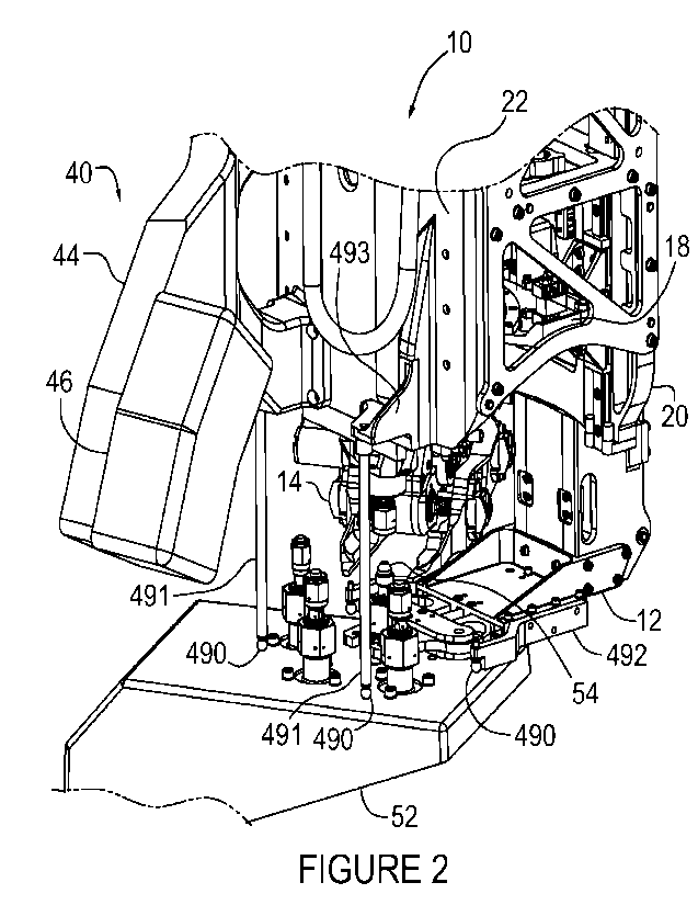
The present disclosure is shown in FIGURES 2 and 2A. Refueling tool
10 is depicted in the process of servicing one of four FDVs 54 arranged in a
symmetrical pattern on a typical FDV bracket 52. Note that one of four the
37
CA 03161013 2022- 6-7
WO 2021/119851
PCT/CA2020/051779
FDVs 54 is shown part way through a refueling operation, wherein the B-nut
has been removed and safety valve 350 is about to be installed. Cameras 42,
beneath camera shield 46 are arranged on camera bracket 44 such that each
camera has a complete view of the worksite and all interactions between the
refueling tool and the target FDV. Alternatively, a prime and redundant camera
pair could be implemented with a single lens and a beam splitter, thus
affording
each camera the ideal view rather than each camera having a view that is
compromised for the sake of the other camera.
The cameras shown are representative of visions systems in the broader
sense. A complete refueling tool vision system may be as simple as a single
camera intended for a human operator, or may comprise a suite of optical
sensors including but not limited to cameras, lidar and laser range finders
more
suitable to an automated, machine vision-based system. Additionally, a single
camera may be used in conjunction with a detailed optical survey performed by
another tool or apparatus on the robotic arm, such that the camera view
relates
the tool position to the target FDV within a computer generated 3D rendering.
In this sense a refueling tool vision system-based architecture encompasses
any optical system used in conjunction with a human or machine operator to
validate the successive states of the refueling operation.
Also visible in FIGURE 2 are four contact spheres 490, one on each of
two touchdown rods 491 and two touchdown arms 492, one of the touchdown
rods mounted to camera bracket 44 and the other to touchdown bracket 493,
the purpose of the contact spheres being to indicate contact between the
refueling tool and the FDV bracket 52 via force/moment sensing and control or
other means within the robotic arm 84. The contact spheres, touchdown rods
and arms shown are representative of a means of touchdown sensing and
could alternatively employ other technologies including but not limited to
proximity sensing and sensing by mechanical actuation of switches by either
direct or indirect means.
FIGURE 2A also shows the elements of refueling tool end effector
interface 500, namely, grasp fixture 501, first rotary input shaft 502, second
rotary input shaft 503, electrical connectors 504 and quick connect nipple
505.
38
CA 03161013 2022- 6-7
WO 2021/119851
PCT/CA2020/051779
The refueling tool consists essentially of a collection of mechanisms, each
with
a specific function, namely, mechanism A 12 for registering to and clamping
onto valve body 56 and torque reaction flats 58, mechanism B1 14 for closing
and opening the wrench, mechanism 62 18 for rotation of the wrench,
mechanism C 20 for elevation adjustment of the rotating wrench, and
mechanism D 22 for connection of the refueling system to the nipple of the
target FDV. Each mechanism requires one independent actuation, except for
mechanism D which requires two.
Mechanism B1 for closing and opening the wrench is compliantly
mounted to mechanism B2 for wrench rotation, which is in turn is mounted to
mechanism C for wrench elevation. Mechanism A for registration and clamping
onto the valve body is also mounted to mechanism C. This sub-structure forms
the torque reaction loop that ensures torque induced by rotating the wrench is
reacted at the valve body via the torque reaction flats, as required. This sub-
structure is connected to mechanism D, which includes the refueling delivery
system and refueling tool top plate 479, which includes the end effector
interface by bolted and pinned connections to side plates 483, thus forming
the
complete refueling tool assembly or structure.
Requiring a high number of separately controlled actuations could be
considered a detriment to this design approach, particularly if each requires
a
discrete actuator, as drive electronics for the discrete actuators may reside
on
the robotic arm, with the associated interconnections passing separably
through
the electrical connectors of the end effector of the robotic arm and the
refueling
tool.
The end effector of the robotic arm optimally has two external tool drives,
since the majority of tools used in the complete refueling operational concept
are passive, externally driven devices requiring one tool drive input for
stowing
and un-stowing and a second tool drive input for operation of the mechanism,
the passive tools (site preparation and refueling support tools discussed
herein
after) including but not limited to those for cutting and manipulating thermal
blankets, cutting and removing lock wire and removing B-nuts and crush seals.
39
CA 03161013 2022- 6-7
WO 2021/119851
PCT/CA2020/051779
In order to minimize the number of discrete actuators, associated drive
electronics, and separable electrical interconnections, a power transmission
device 26 moveably located adjacent to the refueling tool end effector
interface
is used to selectively direct a first end effector rotary drive shaft 502 to
one of 4
discrete outputs, one for each of mechanisms A, B2, C and D. A second end
effector rotary drive shaft 503 is used to actuate the transmission device,
the
actuation being for the purpose of selecting which of the mechanisms to
connect to the first tool drive input. The power transmission device may
optionally include additional mechanisms to perform additional actuations
within
io the refueling tool, such as stowing and un-stowing of the refueling
tool.
Each of the aforementioned mechanisms, and other elements of the
current disclosure are further described in the paragraphs below.
Mechanism A, Register and Clamp, 12
Referring to FIGURES 3A, 3B and 4A and 4b, mechanism A is driven in
a closing motion by clockwise rotation of input shaft 102 supported between
lower thrust ball bearing 103 and upper thrust needle roller bearing 104, the
former selected for the high thrust loads induced by mechanism A clamping
and the latter for the comparatively low thrust loads involved in driving the
mechanism through free space to the fully open position. Clockwise rotation
induces upwards motion of tension assembly 113 comprising tension housing
105, lead nut 106, piston 107 with cross pin 108, springs 109, spacers 110 and
111, end cap 112 and linear bearing rail 114. Cross pin 108 passes through
slots on both sides of tension housing 105. Linear bearing block 115, mounted
to mechanism A frame 128, guides motion of tension assembly 113 and
maintains alignment with input shaft 102. Springs 109, being positioned
between end cap 112 and piston 107, allow for continued upwards motion of
the tension assembly after the rest of the mechanism has contacted the valve
body and stopped moving, such continued motion being used to compress the
springs and produce a predetermined level of clamping load.
Vertical motion of the tension assembly induces horizontal motion of
pushrod 119 via drive links 116, rocker arm 117 and connecting links 118, the
drive links 116 being connected to cross pin 108. Pushrod 119 is guided within
bushing 120 which is contained within mechanism A frame 128. Mechanism A
CA 03161013 2022- 6-7
WO 2021/119851
PCT/CA2020/051779
frame 128 forms the structural framework for aligning the refueling tool 10 to
the
FDV axis 60 via mechanism A mounting interface 129.
Mechanism A jaws 121 rotate on pivots 122 housed within body 128,
and are driven to close symmetrically by rollers 123 contained within roller
bracket 124, as the roller bracket is driven forward towards the target FDV by
virtue of its connection to pushrod 119. Rollers 123 run inside closed slots
within jaws 121 such that the rollers drive the jaws both in the close
direction
and in the open direction, the closed slots being shaped to produce a closing
motion that is fast in the region of stroke allotted to centring, then much
slower
within the region of stroke devoted to clamping, this latter region designed
to
accommodate FDV bodies of various sizes and orientations. The slower
closing motion within this region of stroke devoted to clamping affords a
better
mechanical advantage to the roller bracket 124.
Jaws 121 are each equipped with two grippers 125 which are free to
rotate through approximately 10 degrees. Each gripper has two contact fingers
126 and as the jaws close around the base of FDV 54 one finger from each
gripper will contact the cylindrical surface and the other the torque reaction
flat
58 on valve body 56. This arrangement allows the grippers to close around a
range of valve body diameters in two distinct orientations; with torque
reaction
flats parallel to the mechanism A pushrod and with torque reaction flats
perpendicular to the mechanism A pushrod as depicted in FIGURES 5A, 5B,
5C, 5D, 5E, 5F and 5G,
Prime and redundant microswitches 127 mounted to tension assembly
113 change state from closed to open when springs 109 have reached the
desired compression, the switches informing the operator of the latched
condition.
Mechanism B1, Wrench Closing/Opening, 14
Referring to FIGURES 6A, 6B, 6C, 7A, 7B, 8A and 8B, mechanism B1
is a wrench close/open device based on twin lead screws 150 with right hand
thread and left-hand thread on opposing ends, in a parallel screw clamp
arrangement such that similarly handed threads are on each side of the
assembly with right hand threads on the actuator side. Two wrench jaws 154,
each housing two similarly handed lead nuts 155, are mounted onto the
corresponding lead screw threads on each side of the mechanism B1, the
41
CA 03161013 2022- 6-7
WO 2021/119851
PCT/CA2020/051779
wrench jaws being configured such that the location where the wrench jaws
intersect the FDV axis 60 lies on a line formed by the lead screw centres.
Each
lead nut 155 is retained by nut clamp 156, the lead nut being free to rotate
within the wrench jaw and the nut clamp during initial setup in order to
establish
a parallel arrangement of the wrench jaws. The lead nuts are locked from
rotation thereafter by drilling holes through the nut clamps, lead nuts and
wrench jaws and installing locking pins 157.
The need for B1 actuation to be independent of other mechanism
motion, most notably wrench rotation, combined with the complexity of motion
of the B1 actuation axis, provides ample justification for a discrete actuator
for
this mechanism.
Mechanism B1 housing 152 and B1 cover 153 enclose and locate the
central gear 151 of each lead screw via bearings 172, one in each of the
housing and cover and two idler gears 158 via idler shaft 173 and idler
bearing
174. B1 drive input gear 159 is supported via a pair of bearings 172 located
side by side within the cover, thereby permitting the axis of the drive input
gear
to be exposed through an opening in the B1 housing. Referring to FIGURE 7A,
the B1 drive input gear has, on the exposed drive axis, a torque reacting
recess
175 precisely manufactured to accept torque reacting shaft 176 of B1 drive
actuator 160, the torque reacting recess in this embodiment being in the form
of
a shaft with a flat. The mechanism B1 housing 152 provides a unique mounting
arrangement for B1 drive actuator 160, which is coaxially mounted to a puck-
shaped adaptor 161 made of self-lubricating material. This adaptor is located
and contained within a corresponding recess 162 in the mechanism B1 housing
152, and retained therein by two retaining clips 163. The adaptor is fitted
with
two pins 164 oriented radially on opposing sides of the adaptor such that the
pins are coaxial. B1 housing actuator recess 162 has cut-outs to accommodate
the radially opposed pins and to allow for rotation of the actuator adaptor
with
the pins on the order of 15 degrees. Two spring plunger assemblies, each
comprising a post-mounted plunger guide 165, compression spring 166 and
plunger 167 with bifurcated head 168 are arranged tangentially to the B1
housing actuator recess 162 with the bifurcations straddling the radially
opposed pins such that both spring plunger assemblies exert a counter-
clockwise torque on the actuator adaptor as viewed from the end of the
actuator
42
CA 03161013 2022- 6-7
WO 2021/119851
PCT/CA2020/051779
opposite to the actuator shaft. The torque forces the radially opposed pins to
be seated against one end of the B1 actuator recess cut-outs and collectively
the fit and retention of the actuator adaptor within the B1 actuator recess in
conjunction with the arrangement of spring plunger assemblies allows the
actuator mounted on the adaptor with the radially opposed pins to rotate
clockwise within the B1 housing actuator recess in opposition to the
tangentially
arranged spring plungers when the wrench jaws have closed on an object or
have reached the end of travel in the closed direction.
One of the spring plungers with bifurcated head 168 interacts with a pair
io of microswitches 169 such that the switches are closed when the spring
plungers are fully extended, becoming open as the spring plungers are
compressed, the actuator being commanded to stop when the microswitches
change to the open state. This arrangement causes the actuator to shut off at
a
predetermined torque value regardless of position within the mechanism stroke,
the torque value being determined by the selection of springs for the spring
plungers.
Shoulder bolts 171 installed through the wrench jaws into the B1 housing
and B1 cover define travel limits of the wrench jaws in the closed direction.
Two mounting lugs 170 on B1 housing 152 provide a means for
attachment.
Compliance Mechanism, 16
Residual misalignment between the refueling tool wrench rotation axis
and the FDV axis after clamping onto the FDV body could induce side loads on
the FDV when the wrench is clamped onto the FDV, and also when the wrench
is rotated. In order to minimize the side loads, a small range of spring-
centred
compliance is afforded by the compliance mechanism, in both radial and
tangential directions.
Referring to FIGURES 9A, 9B, 10A, 10B and 10C, a rectangular
coupling platform 204 features a coaxial pair of protruding lugs 205 along
each
of two parallel first edges on the upper side of the platform such that each
lug is
near a platform corner. A similar arrangement of coaxial pairs of protruding
lugs 205 is similarly placed on the underside of the platform along two edges
that are perpendicular to the first edges, the first edges being oriented
radially
with respect to the workspace of the FDV and the second edges being oriented
43
CA 03161013 2022- 6-7
WO 2021/119851
PCT/CA2020/051779
tangentially with respect to the workspace. Ball bushings 206 are fitted into
the
protruding lugs on both sides of the platform, the bushings being secured to
the
protruding lugs by a bushing circlip 207 placed at both ends of the ball
bushings, the circlips straddling the protruding lugs.
A first pair of precision shafts 208 is supported within the ball bushings
on the upper side of the platform, one shaft per pair of coaxial pair of
bushings,
such that at least 3 mm of shaft extends beyond the outward ends of the
coaxial pairs of bushings. Coupling bracket 202 is mounted onto, and straddles
the first pair of precision shafts on the upper side of the platform via a
pair of
down-swept protrusions 203 symmetrically located on each of two sides of the
coupling bracket, the pairs of down-swept protrusions being spaced to
accommodate length-adjustable locking shaft collars 210 between them, the
shaft collars being used to secure the coupling bracket to the precision
shafts
centrally between the pairs of ball bushings, adjustment of the length-
adjustable
locking shaft collars being used to eliminate free play between the coupling
bracket and the first pair of precision shafts. A pair of compression springs
211
placed on each of the first pair of precision shafts on the upper side of the
platform, each one located between a ball bushing 206 and a down-swept
protrusion 203, each of the compression springs partially compressed at
installation, permit limited, spring-centred bilateral motion of the coupling
bracket, shafts and shaft collars with respect to the coupling platform,
parallel to
the axes of the first pair of precision shafts.
A second pair of precision shafts 209 is supported within the ball
bushings on the underside of the platform, one shaft per pair of coaxial pair
of
bushings, such that at least 3 mm of shaft extends beyond the outward ends of
the coaxial pairs of bushings. Mechanism B1 14 is mounted onto, and
straddles the second pair of precision shafts via B1 mounting lugs 170. The
mounting lugs are secured to each of the second pair of precision shafts via
two
length-adjustable locking shaft collars 210 per shaft, one on either side of
each
of the mounting lugs, at a central location on the shafts, adjustment of the
length-adjustable locking shaft collars being used to eliminate free play
between the mechanism B1 and the second pair of precision shafts. A pair of
compression springs 211 placed on each of the second pair of precision shafts
on the lower side of the platform, each one located between a ball bushing 206
44
CA 03161013 2022- 6-7
WO 2021/119851
PCT/CA2020/051779
and a length-adjustable locking shaft collar 210, each of the compression
springs partially compressed at installation, permit limited, spring-centred
bilateral motion of the mechanism B1, shafts and shaft collars with respect to
the coupling platform, parallel to the axes of the second pair of precision
shafts.
Torque cell 201 is mounted between coupling bracket 202 and torque cell plate
200, the torque cell plate including the mounting interface 212 of the
compliance mechanism to the mechanism B2.
Mechanism B2, Wrench Rotation, 18
Mechanism B2 is a wrench rotation device designed to rotate wrench
close/open mechanism B1 through a hard stop limited arc of 70 degrees in
either the clockwise or counter-clockwise direction, thus achieving one full
turn
of a hexagonal feature in six increments by repeatedly closing and opening the
B1 mechanism in concert with back and forth rotation through 60 degrees, the
extra 10 degrees being a buffer between commanded motion and end of travel.
Incremental rotation allows for the mechanism to occupy primarily one side of
the volume surrounding the FDV axis, thus permitting a clear view of the
overall
operation via cameras situated on the opposite side of the volume.
Referring to FIGURES 11A and 11B, 12A to 12 D and 13A and 13B,
segment gear assembly 256, comprising segment gear 257, end-of-travel pin
260, segment gear carrier 258, a first pair of track rollers 259 and tensioner
assembly 261, itself comprising a second pair of track rollers 263, tensioner
yoke 262, tensioning screw 264 and disc springs 265, is constrained to rotate
about wrench rotation axis 270 via contact and preload between precision
rolling surfaces 268 of rotation track plate 250 and the first pair and the
second
pair of track rollers, the former in contact on the outer precision rolling
surface
and the latter on the inner, the precision rolling surfaces being sufficient
in arc
to allow plus and minus 35 degrees of rotation of the segment gear assembly
about a central position, with a thickening of the rim formed by the precision
rolling surfaces beyond the arc forming travel stops, the wrench rotation axis
being defined by the precision rolling surfaces.
Mechanism B2 drive housing 253 supports lead nut 155 and nut clamp
156, the lead nut being locked against rotation within the B2 drive housing
and
the nut clamp by locking pin 157. B2 drive gear 251 with internally-splined
hub
252 is supported via bearings 254 housed in the B2 drive housing and the
CA 03161013 2022- 6-7
WO 2021/119851
PCT/CA2020/051779
rotation track plate. The segment gear assembly is constrained along the
wrench rotation axis by segment gear bumper 269 and thrust pad 255, the
former mounted to the rotation track plate and the latter to the B2 drive
housing.
Pairs of microswitches 266 separated by microswitch spacers 267 are
mounted in stacked configurations via slots in the rotation track plate near
each
end of the range of motion of the end-of-travel pin mounted within the segment
gear, the slots permitting the adjustment of the stacked pairs of
microswitches
such that they change from a free state to an operating state to signal an end
to
rotation in advance of the travel-limiting thickening of the rim formed by the
precision rolling surfaces. Elevation travel indicator 271 is mounted to the
rotation track plate.
Mechanism C, Wrench Elevation, 20
Mechanism C is an elevation stage for the wrench rotation mechanism
B2 which requires mechanism B2 to be present in order to function as a
mechanism. Consequently, FIGURE 14A depicts mechanism C parts alone,
while FIGURE 14B, from the same perspective, includes mechanism B2 for
clarification.
Referring to these figures, and FIGURE 15 from a different perspective, back
plate 300, including interface to mechanism A 129, and mid plate 301 are
secured together and form a basis for the RT structural frame. A pair of
linear
bearing rails 303 are secured to the inward-facing side of the back plate
oriented vertically and widely spaced on the back plate. A pair of linear
bearing
blocks 304 are precisely guided on each of the linear bearing rails. Right
angle
brackets 305 are mounted to the linear bearing blocks, one per the block and
arranged like bookends, such that each pair of the brackets straddle and
support rotation track plate 250 of mechanism B2 18. A pair of non-metallic
bumpers 306 mounted to the back plate at each end of each of the linear
bearing rails define the limits of travel.
A pair of retracted microswitches 307 is mounted via slots in the back
plate, near the upper end of travel of elevation travel indicator 271 of
mechanism B2 18, the slots permitting the adjustment of the retracted
microswitches such that they change from a free state to an operating state to
signal an end to mechanism C motion in the upwards direction prior to contact
46
CA 03161013 2022- 6-7
WO 2021/119851
PCT/CA2020/051779
with the non-metallic bumpers. A pair of extended microswitches 311 is
similarly mounted via slots in the back plate, near the lower end of travel of
elevation travel indicator 271, the slots permitting the adjustment of the
extended microswitches such that they similarly signal an end to mechanism C
motion in the downwards direction prior to contact with the non-metallic
bumpers. It will be appreciated that the present system and tools uses sensing
means that are microswitches but it will be appreciated other types of sensors
may be used, a non-limiting example being potentiometers.
Bearings 308 mounted within mid plate 301 support mechanism B2
spline shaft 309 and mechanism C lead screw 310, the spline shaft aligning and
interfacing with internally-splined hub 252 of B2 drive gear 251, thus
transferring torque to the B2 drive gear regardless of mechanism C position,
the lead screw aligning and interfacing with lead nut 155 of mechanism B2 18
in order to drive mechanism C through its range of motion.
Mechanism D, FDV Connection, 22
Mechanism D 22 is used to connect the refueling system to the FDV
nipple 70 via the installation of a safety valve 350. The safety valve 350 is
a
non-latching quick connect device with a secondary check valve and is
designed to be mounted to an FDV permanently in place of the B-nut after the
B-nut has been removed. Once installed, it acts as a safe fluid coupling to
pass
fuel or oxidizer through a FDV into the client spacecraft, providing two
independent seals against leakage beyond the seat of the actuation nut of the
FDV, which is itself the primary seal in the line. Referring to FIGURES 16A
and
16B, the safety valve 350 comprises a valve body 351 with external capture
groove 352, coupling nut 353 and spring 354, the valve body featuring a fully
independent check valve 356 and a quick connect nipple 355 which is
essentially another check valve that is either forced open by the act of
coupling
or by the application of pressure via flowing gas or liquid after coupling.
The quick connect coupling and nipple are of a non-latching variety.
Specifically, unlike the vast majority of quick connect systems in common
usage, known as latching quick connects, which latch together via the
interaction of detent balls and a groove, the locking action being released by
the axial movement of a spring-loaded external locking collar, the non-
latching
47
CA 03161013 2022- 6-7
WO 2021/119851
PCT/CA2020/051779
quick connect coupling and nipple require an externally applied force to
maintain the connection of the coupling and nipple. A latching quick-connect
coupling design could be adopted in another embodiment, though the latching
function is superfluous when used with the refueling tool as presented here.
The safety valve 355 is designed to be installed on the FDV after
removing the b-nut and prior to passing fuel or oxidizer. Once fuel or
oxidizer is
transferred through the safety valve 355, the safety valve 355 is left on the
client valve. The quick connect coupling on the safety valve 355 enables
subsequent refueling operations of the client satellite 81 at later points in
time to
io be more quickly and safely performed, with the refueling operation no
longer
requiring the removal or re-installation of the b-nut or the actuation of the
valve
actuation nut to open or close it, with the added advantage that leakage
outboard of the valve actuation nut is now being mitigated through the check
valve and quick disconnect coupling.
As shown in FIGURES 17 through 20, Mechanism D 22 features two
independent coaxial actuations of two carriages; hereafter referred to as D1
actuation and D2 actuation. Mechanism D2 actuation is dedicated to capturing
and holding onto the safety valve and thereafter the ability to mate and de-
mate
the propellant delivery system of the robotic arm to the safety valve via
actuation of a quick connect coupling 385 in order to force together the
coupling
and the nipple. Mechanism D1 actuation is dedicated to acquisition of and
manipulation of the safety valve along the FDV axis in order to remove it from
a
storage location and install it on an FDV, the height of the FDV being
dependent on the variety of FDV being accessed. The D2 actuation results in
motion between mate/de-mate carriage assembly 380 and safety valve carriage
assembly 367. The mechanism D1 actuation results in motion between the
safety valve carriage assembly and mechanism D baseplate 360, the safety
valve carriage assembly carrying all components of the D2 actuation, the D1
and D2 actuations being along the FDV axis in both a first direction and a
second direction, the first direction being towards the FDV and the second
direction opposite to the first direction.
The current embodiment uses a discrete actuator for the D2 actuation.
Optionally the D2 actuation could be performed by an additional mechanism
within transmission 26.
48
CA 03161013 2022- 6-7
WO 2021/119851
PCT/CA2020/051779
Referring to FIGURES 19 & 20, a first set of linear guide rails 362 is
mounted to the mechanism D base plate 360, along with, four (4) adjustable
end stops 363, and two dual microswitch assemblies 364, the microswitch
assemblies acting to limit the commanded motion of the safety valve carriage
assembly. Each of the dual microswitch assemblies includes advance
microswitch 417 and retract microswitch 418.
The safety valve carriage assembly includes safety valve carriage 368
with two locking arm posts 370 along the edge of the safety valve carriage
closest to the FDV and symmetrically spaced about the FDV axis, the posts
forming short-stroke rotation centres for two symmetrical safety valve locking
arms 372, mounted on flanged bushings 371, the distal ends of the locking
arms being shaped to collectively form a diameter compatible with the external
capture groove of the safety valve body, the locking arms each including a
precisely shaped actuation slot 373 on the side adjacent to the mate/de-mate
carriage assembly. Linear guide blocks 369, safety valve sensor assembly 374,
compliant coupling assembly 375, first actuation actuator 376, microswitch
striker 377 and a second set of linear guide rails 378 are all mounted to the
safety valve carriage, the linear guide blocks maintaining precise alignment
to
the mechanism D base plate via the first set of linear guides.
Mate/de-mate carriage 381 forms the platform for the mate/de-mate
carriage assembly and includes two track rollers 383 symmetrically spaced
about the FDV axis along the edge closest to the FDV, the track rollers
residing
in the actuation slots of the locking arms such that relative motion between
the
mate/de-mate carriage assembly and the safety valve carriage assembly in the
first direction causes the locking arms to swing towards each other and to fit
precisely within the external locking groove of the safety valve, the
precision
slots being shaped to produce first a rapid closing motion to the closed
position
and thereafter to maintain the locking arms in the closed position while
allowing
continued motion of the mate/de-mate carriage assembly, the continued
motion being optionally exercised only when attempting to fully mate the quick
connect coupling and nipple.
Also mounted to the mate/de-mate carriage are linear guide blocks 382,
lead nut 384, quick connect coupling 385, manifold 386 with travel stop 388,
and dual microswitch assembly 387, the linear guide blocks ensuring precise
49
CA 03161013 2022- 6-7
WO 2021/119851
PCT/CA2020/051779
alignment between the mate/de-mate carriage assembly and the safety valve
carriage assembly via the second set of linear guides, the lead nut completing
the connection to the mechanism D2 actuator, the dual microswitch assembly
interacting with the microswitch striker to signal the end of travel in the
first
direction.
Relative motion of the mate/de-mate carriage assembly with respect to
the safety valve carriage assembly in the second direction correspondingly de-
mates the quick connect coupling and nipple if mated and then fully releases
the safety valve.
The shape of the actuation slots in the locking arms ensures that the
commanded motion of the mate/de-mate carriage with respect to the safety
valve carriage can only be completed when the shaped ends of the locking
arms coincide with the external locking groove of the safety valve, the
external
locking groove of the safety valve being shaped with generous lead-in to
assist
with the alignment. Excessive misalignment causes the locking arms to close
around the outer diameter of the safety valve instead of the external locking
groove, causing the D2 actuation to stall and preventing the mate/de-mate
carriage from completing the commanded motion, the commanded motion
being aborted by a current limit on the D2 actuation.
To further assist in the alignment of the locking arms with the external
locking groove of the safety valve, the D2 actuation is triggered by safety
valve
sensor assembly 374 comprising sensor housing 405 and sensor base 406,
both of a self-lubricating material, trigger plate 407, prime and redundant
ready-
to-latch microswitches 408, compression springs 409 and limiting pin 410, the
compression springs selected to be installed with preload and final load
chosen
in consideration of robotic arm performance, force-moment sensing capabilities
and/or techniques if any, and FDV load limits, the limiting pin acting within
a slot
within the housing, the slot commensurate in length with microswitch stroke.
The microswitches, in contact with one side of the trigger plate, change state
when contact between the opposite side of the trigger plate and the top
surface
of the safety valve result in motion of the trigger plate sufficient for the
indication.
CA 03161013 2022- 6-7
WO 2021/119851
PCT/CA2020/051779
Flexible hose 365 is also shown in FIGURES 19 and on the opposite
side of mechanism D baseplate 360 and includes a right angle fitting which
passes through a slot in the baseplate to form a connection with manifold 386.
The D1 actuation, between mechanism D base plate 380 and safety
valve carriage assembly 367, is accomplished via rotation of splined input
shaft
390 which drives safety valve lead screw 394 via gears 392 and bearings 393
housed within drive bracket 391, the drive bracket being rigidly mounted to
the
mechanism D base plate. Rotation of the lead screw induces linear motion of
lead nut 395 contained within guide housing 396, the housing supporting guide
pin 397, and connecting pins 398, the guide pin and connecting pins forming a
connection to compliant coupling assembly 375 permitting limited, bi-lateral,
spring-centred compliance between the safety valve carriage and the D1
actuation, the compliance afforded by the action of shuttles 402 and springs
403 contained within compliance housing 400 and compliance base 401, both
made of a self-lubricating material.
Compliance microswitch 415 mounted to the guide housing and
interacting with compliance striker 416 mounted to the safety valve carriage,
changes state when motion of the safety valve carriage assembly in the first
direction is arrested by contact between the safety valve and the FDV, the
change of state signaling an end to forward motion. Thus the compliance
microswitch serves effectively as a touch sensor to indicate readiness for
safety
valve installation.
Transmission, 26
The transmission 26 is used to selectively direct a first end effector tool
drive input to one of 4 drive outputs 456, each of the drive outputs being a
rotating gear with an internally-splined hub 457, the internally splined hubs
being compatible in size and relative position with the splined input shafts
of the
mechanisms A, B2, C and D.
Referring to FIGURE 21, transmission housing 450, top cover 451 and
bottom cover 452 enclose and support transmission gears 453 arranged in 4
distinct layers, each of the layers designed to transfer torque from an input
gear
454 to an output gear 456, the input gear of each layer being arranged on a
common axis 455. Each of the input gears features an internally splined hub
457 and is supported on a bearing 458 within a support housing 459. The input
51
CA 03161013 2022- 6-7
WO 2021/119851
PCT/CA2020/051779
gears, each with the bearing and support housing, and thrust washers 460 are
arranged in a stack within the transmission housing, and contained by the top
and bottom covers, such that one of the thrust washers is between the bottom
gear in the stack and the bottom cover and one of the thrust washers is
between each successive gear and the support housing beneath it and one of
the thrust washers is between the support housing of the top gear and the top
cover. Remaining gears, including the output gears, are straddle mounted on
two bearings 458, one bearing in the transmission housing and the other in one
of the top and bottom covers.
The transmission is moveably mounted via mounting bracket interfaces
467. Lead nut 468 and nut clamp 469 mounted to the transmission housing
form the interface by which the transmission is actuated.
FIGURE 22 includes a section view of the stack of the input gears,
bearings and support housings, Each of the support housings has the form of a
disk with a central hole, with a complete rim 461 on the inner diameter and a
partial rim 462 of approximately 300 degrees of arc on the outer diameter, the
complete inner rim forming a hollow shaft for the bearing, the partial outer
rim
forming a cover over the gear teeth of the input gear except for the missing
segment, the missing segment of outer rim of the support housing allowing the
input gear to mesh with another gear. Visible in FIGURE 21 the outer diameter
of the partial outer rim of the support housings are interrupted by three
cylindrical grooves 463. The bore 464 within the transmission housing which
precisely locates the support housings via the outer diameter is also
interrupted
by a hole 465 parallel to the axis of the transmission housing bore and
breaking
through the cylindrical wall of the bore, such that the axis of each of the
grooves
on the outer diameter of the support housings can be made to align with the
axis of the hole in the transmission housing by rotating the support housing
within the transmission housing bore. Locating pin 466 fitted within the hole
in
the transmission housing forms a locating feature along the full length of the
bore, such that the support housings can only be installed in one of three
rotational orientations, each of the three orientations being determined by
one
of three the cylindrical grooves, thus ensuring that the outer rim openings of
support housings of the input gears maintain alignment with the next gear in
each layer. In the current embodiment three grooves are sufficient for four
52
CA 03161013 2022- 6-7
WO 2021/119851
PCT/CA2020/051779
layers of gearing only because two non-adjacent layers share similar output
directions. Another embodiment may require one groove per layer of gearing.
Additionally, the only reason to include all grooves on all support housings
is
one of interchangeability. Alternatively, each support housing could be made
for a specific layer, with a single groove correspondingly placed.
Each of FIGURES 23A through 23D show a section view of the
transmission through one of the four layers of gearing. Each layer includes
one
of the input gears, one or two idler gears and one of the output gears.
FIGURE 24 is a section view immediately below refueling tool top plate
479 showing transmission 26 mounted on two linear guide rails 471 via linear
guide blocks 472 and transmission brackets 470. The linear guide rails are
mounted to transmission support plate 473, the support plate being located and
supported between top plate 479 and mid plate 301 with bolted and pinned
connections.
Also shown in FIGURE 24 are linear potentiometer 476, potentiometer
bracket 477 and potentiometer rod bracket 476. The body of the linear
potentiometer, mounted to refueling tool mid plate 301 via the potentiometer
bracket, remains stationary while the potentiometer rod bracket, mounted to
transmission 26, moves with the transmission, thereby reporting the position
of
the transmission within its range of motion.
FIGURE 25 is a top view of refueling tool 10, showing the elements of
refueling tool end effector interface 500, namely; grasp fixture 501, first
rotary
drive input 502, second rotary drive input 503, electrical connectors 504 and
quick connect nipple 505. The quick connect nipple is mounted to fuel channel
513, the fuel channel providing a sealed delivery passage to flexible hose 365
of mechanism D 22. A breakout section in FIGURE 25 reveals first rotary drive
input gear 507 transferring the first rotary drive input to quill shaft 509
via
transfer gears 508 and quill shaft drive gear 514, the gears supported and
enclosed within transfer housing 515.
FIGURE 26 is a section view of quill shaft 509, quill shaft drive gear 514
and the stack of transmission input gears 454. The quill shaft is located and
supported at the lower end by bearing 510 and bearing retainer 511 in mid
plate
301. The upper end of the quill shaft is supported by quill shaft external
splines
512 engaged in corresponding internal splines of quill shaft drive gear 514. A
53
CA 03161013 2022- 6-7
WO 2021/119851
PCT/CA2020/051779
second set of external splines 512, approximately midway along the length of
the quill shaft is sized and located to engage with the lowest transmission
input
gear 454 in the stack when the transmission is at the upper end of
transmission
range of motion 485, the range of motion being sufficient to allow the second
external spline to engage with each of four the transmission input gears. A
breakout section in FIGURE 25 reveals transmission lead screw 484 of second
rotary input 503 and lead nut 474 mounted to the transmission such that the
second rotary input can be used to drive the transmission on the linear guides
through the range of motion.
FIGURE 27 shows conceptually a dexterous end effector 550 with the
necessary components for a refueling operation, namely; grasp mechanism
551, first rotary drive socket 552, second rotary drive socket 553,
robotically
mate-able electrical power and data signal connector drive electrical
connectors
554, movable quick connect propellant couplings 555 and cameras 556. The
propellant couplings 555 are connected upstream via hoses to the propellant
transfer system 960. Cameras 556 provide close-in views of the grasping
fixture 501 on refueling tool 10 prior to grasping by end effector 550 and
similarly, the grapple fixture 610 prior to grasping by end effector 550 of
any of
the refueling support tools (608, 609) or site preparation tools (605, 606,
607).
In one embodiment of the refueling system, a fiducial mark or machine vision
target (not shown) is placed adjacent to grasp fixture 501 on top plate 479.
This enables the processor 830 in computer control system 800 to compute the
position of the grasp fixture 610 based on video stream images of the target
obtained from cameras 556. This position can be used to guide the motion of
the robotic arm 84 by the automatic control system 830 to the ready-to-grasp
position of the grapple or grasp fixture. Alternatively, a video display of
that
fiducial mark can be displayed to a human tele-operator, to help them guide
the
motion of robot arm 84 to the ready-to-grasp position. The refueling support
tools (608, 609) and site preparation tools (605, 606, 607) can be similarly
equipped with fiducial marks or targets on common tool base structure 620,
adjacent to grapple fixture 610. These cameras 556 could also be used to
monitor the action of the tool tips of the blanket cutter tool 605, blanket
handling
tool 606, wire Cutter Tool 607, B-Nut Removal Tool 608 and crush seal removal
tool 609.
54
CA 03161013 2022- 6-7
WO 2021/119851
PCT/CA2020/051779
In operation, after the servicer spacecraft 80 has captured the client
satellite 81 with berthing device 950 and after the FDV worksite 50 has been
prepared using the robotic arm 84 and supporting tools in a succession of
operations to expose the FDV 54, the robotic arm 84 then brings refueling tool
10 to the FDV worksite 50 and into alignment with the selected FDV 54 axis,
thereafter approaching along the FDV axis to effectively lower the refueling
tool
onto the FDV bracket 52. The refueling tool vision system 40 of the refueling
tool 10 provides the primary means for sensing the correct alignment of the
refueling tool 10 to the FDV 54 and monitoring the approach to the FDV bracket
10 52 until contact between contact spheres 490 of the touchdown sensing
system
and the FDV bracket 52 is sensed by force/moment sensing or other means
within the robotic arm 84 or tool.
Actuation of mechanism A 12 then causes the mechanism A 12 to close
symmetrically around the valve body 56 and torque reaction flats 58, bringing
the refueling tool 10 and the FDV 54 into final alignment, thereby clamping
onto
the valve body 56 and the torque reaction flats 58. An operator, using
primarily
the view from the camera 42, now uses mechanism C 20 to lower the wrench
jaws 154 into position near the mid height of the actuation nut 62, having
first
confirmed through the view from the camera 42 that mechanism B1 14, for
wrench closing and opening, is sufficiently open. Mechanism B2 18, for wrench
rotation, is then adjusted so that the wrench jaws 154 are parallel to a pair
of
flats on the actuation nut 62 nearest the middle of the wrench rotation range
of
motion. Mechanism B1 14 is then commanded in the closing direction. As the
wrench jaws 154 close, an operator may pause to further adjust wrench rotation
or wrench elevation into more precise alignment using mechanisms B2 18 and
C 20 respectively.
When satisfied that the alignment between wrench jaws 154 and
actuation nut 62 is good by checking the view from the camera 42, an operator
commands the wrench jaws 154 to fully close, where the closing action stops
automatically when the mechanism B1 14 has achieved a preset level of torque
as determined by the preload microswitch 169 of mechanism B1 14. Once the
actuation nut 62 is within the wrench jaws 154, an operator commands a
clockwise rotation at a preset level of torque in order to ensure the
actuation nut
is closed. These activities ensure the actuation nut 62 is fully closed prior
to any
CA 03161013 2022- 6-7
WO 2021/119851
PCT/CA2020/051779
subsequent operations on the FDV 54 to prepare it for refueling. After the
preset level of torque has been applied, regardless of whether or not the
actuation nut 62 has rotated, the actuation nut will be released and the
wrench
jaws 154 will be reconfigured into a similar alignment with the B-nut 64 at
the
top of the FDV 54 using mechanisms B1 14, B2 18 and C 20 for wrench
opening/closing, wrench rotation and wrench elevation respectively. After
aligning with and closing on the B-nut 54 using the same methodology as just
described for the actuation nut 62, mechanism B2 18 is actuated in a counter
clockwise direction. Unlike the actuation nut 62, the B-nut 64 must rotate for
successful completion of this step. Rotation of about one quarter turn is
required to ensure sufficient loosening of the B-nut 64 by the refueling tool
10,
and this is achieved by iteratively closing, then COW rotation, then opening,
then OW rotation of the wrench jaws 154.
The refueling tool 10 is then stowed on the servicer spacecraft 80 in
order to use the B-nut removal tool 608 and crush seal removal tool 609 to
remove the B-nut 64 and crush seal 702 respectively from the FDV 54. After the
B-nut 64 and crush seal 702 are removed and discarded safely on the servicer
spacecraft 80 using the B-nut removal tool 608 and the crush seal removal tool
609, the robotic arm 84 once again acquires the refueling tool 10 from its
stowed location on the servicer spacecraft 80 and uses it to acquire a safety
valve 350, also from a stowed location on the servicer spacecraft 80. Using
the
same approach methodology at the safety valve stowed location, and similarly
using mechanism A 12 to close around the base of the safety valve stowed
location, the safety valve carriage assembly 367 of mechanism D 22 is
commanded to advance until trigger plate 407 contacts the safety valve
shoulder 357, tripping the ready-to-latch microswitch 408.
The mate/de-mate carriage assembly 380 is then advanced causing
locking arms 372 to close around the safety valve assembly 350 and lock into
an external locking groove 352 of the safety valve assembly 350, with
confirmation of the closing action coming from the view from the camera
42. The mate/de-mate carriage assembly 380 is further advanced to fully mate
the quick connect 355 on the safety valve assembly 350 to the quick connect
coupling 385 on the refueling tool 10 and as confirmed by the dual microswitch
assembly 387.
56
CA 03161013 2022- 6-7
WO 2021/119851
PCT/CA2020/051779
Thereafter mechanisms B1 14, B2 18 and C 20 are used to align the
wrench jaws 154 to the flats of the coupling nut 353 of the safety valve
assembly 350, to close onto the coupling nut 353 and to loosen and rotate the
coupling nut 353 through a predetermined number of rotations in order to
release the safety valve assembly 350 from the stowage location, where
the loosening of the coupling nut 353 is accommodated by axial motion of the
coupling nut 353 afforded by spring 354 of the safety valve assembly 350. The
safety valve assembly 350 is then fully retracted into mechanism D 22 by
retracting the safety valve carriage assembly 367 and as confirmed by the
safety valve carriage assembly 367 retracted microswitch 418. After
transferring
the safety valve assembly 350 back to the FDV worksite 50 and re-registering
and re-clamping to the FDV valve body 56 and torque reaction flats 58, the
safety valve carriage assembly 367 with the safety valve assembly 350 is
commanded towards the FDV 54 until the coupling nut 353 comes into contact
with the FDV 54, the contact being evident in the camera view by compression
of the safety valve spring 354 as well as being indicated by compliance
microswitch 415 of mechanism D 22.
Mechanisms B1 14, B2 18 and C 20 are then used to manipulate the
wrench jaws 154 into position at the coupling nut 353, to close on the
coupling
nut 353, and to iteratively rotate the coupling nut 353 in the CW direction
while
monitoring the view from the camera 42 for progress. The same spring-resisted
motion that tripped the compliance microswitch 415 to indicate contact between
safety valve coupling nut 353 and FDV nipple 70 ensures there is always a
small force acting to push together the threads of the coupling nut 353 and
the
FDV nipple.
Once the safety valve assembly 350 has been installed on the FDV 54,
thereafter mechanisms B1 14, B2 18 and C 20 are used to align the wrench
jaws 154 to the actuation nut 62 and to loosen and rotate the actuation nut 62
through a predetermined number of rotations in order to fully open the
actuation
nut 62 for subsequent fluid transfer. Once fluid transfer is complete from the
servicer spacecraft 80 through the refueling tool 10, through the check valve
356 of the safety valve assembly 350 into the FDV 54 and thus into the client
spacecraft 81, thereafter an operator confirms alignment of the wrench jaws
154 to the actuation nut 62 and if required, thereafter uses mechanisms B1 14,
57
CA 03161013 2022- 6-7
WO 2021/119851
PCT/CA2020/051779
B2 18 and C 20 to align the wrench jaws 154 to the actuation nut 62. The
wrench jaws 154 are then commanded to rotate the actuation nut 62 through a
predetermined number of rotations in order to fully close the actuation nut 62
after completion of fluid transfer. The mate/de-mate carriage assembly 380 is
then retracted until the quick connect 355 on the safety valve assembly 350 is
de-mated from the quick connect coupling 385 on the refueling tool 10 and as
confirmed by the dual microswitch assembly 387.
The mate/de-mate carriage assembly 380 is then further retracted to fully
open the locking arms 372 from the external locking groove 352 of safety valve
assembly 350, with confirmation of the opening action coming from the view
from the camera 42. The safety valve assembly 350 is left behind on the client
spacecraft 81 after refueling is complete and the refueling tool 10 is
subsequently mated to a safety valve fixture 83 on the servicer spacecraft 80
to
purge propellant hose 980 and refueling tool 10 through the safety valve
fixture
83 prior to stowing the refueling tool 10 on the servicer spacecraft 80.
Supporting Tools
Referring to FIGURES 28 to 36, support tools 601 for refueling are
independent tools used for specific steps in the refueling flow. Each of these
tOOIS 601 has a common tool base structure 603 and a specific tool tip,
designed for the specific task the tool is required for. The common tool base
603 allows for a single robotic interface to a manipulator system with a
specific
'end-of-arm-assembly', while allowing for several tasks to be accomplished.
The common base structure 603 is made up of a grapple fixture 610, the
grasping interface for the tool designed for robotic grasping by the 'end-of-
arm-
assembly' located in the end effector 550 of robotic arm 84 mounted on the
servicer spacecraft 80, see FIGURE 54 Based structure 603 further includes
tool mechanism drive interface(s) 612 and 613, used for enacting the functions
of a given tool via a drive actuator mechanism that resides on the 'end-of-arm-
assembly'. In the embodiment described herein there are two (2) tool
mechanism drive inputs, one of which is used to drive the specific tool tip on
each of the support tools, and the second to drive a 'fie-down' mechanism for
retaining the tool when not grasped by the manipulator system. Base 603
includes a tool mechanism gear train 614 that transfers the rotation and
torque
58
CA 03161013 2022- 6-7
WO 2021/119851
PCT/CA2020/051779
from one of the tool mechanism drive input interfaces to the tool tip
driveshaft
634 via the tool mechanism gear train interface 632, for actuation of that
tip.
Base 603 includes a tie-down mechanism 'active-half 618, driven by the
second tool mechanism drive 613 interface either directly, or in an alternate
embodiment through another gear-train transmission to the location of the
alternate tie-down mechanism. Base 603 includes a structure 620 that holds the
constituent components of the common base 603 together.
The common tool base 603 has an interface to the tool tips 630, which
are permanently attached to an instance of the common base tools 603 at the
io tool tip to tool base geartrain interface 632 and the tool tip bolted
interface 638.
This interface involves a feature that allows for the transfer of rotary
mechanical
power from the tool mechanism gear train interface 632 to the tool tip drive
shaft 634. The main structure 636 of the tool tip is rigidly connected to the
common tool base 603, in this embodiment through the use of a bolted
interface 638.
There are several functions in the refueling operations that are allocated
to the support tools. These include site preparation tools which include a
blanket cutter to 605, a blanket handler tool 606, and a wire cutter tool 607.
The tool tips 630 of the three site preparation tools are all similarly
designed,
whereby they all require a simple scissor-action linkage to perform their
function. Refueling support tools include a B-nut removal tool 608 and a crush
seal removal tool 609. These will each be described below.
Site Preparation Tools
Referring to FIGURES 37 to 39, in each of the site preparation tool tips,
the blanket cutter 650, the blanket handler 652 and the wire cutter 654, the
tool
tip drive shaft 634 is internally threaded and an advancing threaded rod 640
is
installed in the drive shaft 634. The rotation of the drive shaft 634 causes
the
linear movement of the advancing threaded rod 640 which in turn moves a set
of short input linkages 642 which in turn cause the output linkages 644 to
pivot
about a specific point in the given tool tip causing the device action
features to
open or close, depending on the direction of motion. These action features are
cutting shears 645 in the blanket cutter 650, tweezer gripping paddles 646 in
59
CA 03161013 2022- 6-7
WO 2021/119851
PCT/CA2020/051779
the blanket handler 652 and a shear cutter with gripper feature 647 in the
wire
cutter 654.
B-Nut Removal Tool Tip
Referring to FIGURES 40 to 45, B-Nut removal tool tip 660 stages
motion into two parts. Initially the collet 662 is driven forward by the
rotation of
the drive shaft 664 due to the cam-pins 666 that run in slots 668 on the
collet
662 until the spring wrench fingers 670 contacts the B-Nut hex 672 and/or the
cam pins 666 reach the end of the collet slots 668. The drive shaft 664 then
continues to rotate forcing the ratchet disk 674 interface to separate,
causing
the pin carrier housing 676 to rotate with the collet 662 and spring fingers
670,
and in doing so the B-Nut 64, captured by the shape of the closed spring
fingers 670 is threaded off of the FDV 54. To discard the B-Nut 64, the drive
shaft 664 is rotated in the opposite direction than previously described. The
ratchet disk 678 restricts motion of the pin carrier 676 in this direction,
forcing
the collet 662 to retract and allow the wrench spring fingers 670 to open,
thus
releasing the B-Nut 64.
The ratchet disc 678 controls the rotary motion of the pin carrier housing
676 by being keyed 682 against rotation with respect to the tool-tip base
structure 680 while being preloaded against the pin carrier housing 676 with a
preload spring 684. The ratchet disc surface 686 and the mating surface 688 of
the pin carrier housing 676 have mating ramp features. In one direction, where
the shallow angled surfaces of the ramps slide against each other motion is
permitted, which is rotation of the tool to remove the B-Nut 64, only when the
input torque is enough to slide the ramps over each other while under the
preload spring 684 preload that pushes the ratchet disc 678 against the pin
carrier housing 676. In the other direction the steep side of the ramps engage
and relative motion is inhibited in that direction, allowing the collet 662 to
move
to release the B-Nut 64. The drag in the ratchet disc interface 674 allows for
axial motion of the collet 662 to occur ahead of rotary motion.
Crush Seal Removal Tool
Referring to FIGURES 46 to 50, the crush seal 702 may be adhered to
the FDV valve stem 716 and must be removed prior to installing the safety
CA 03161013 2022- 6-7
WO 2021/119851
PCT/CA2020/051779
valve 350 with a new crush seal 702. To operate the crush seal removal tool
tip
700 the drive shaft 704 rotated, which translates the plunger 706 backwards
into the drive shaft 704. The drive shaft 704 has an internal thread while the
plunger 706 an external thread where they interface 708. While the plunger
706 translates, the pivot point 710 of the flex jaw linkages 712 moves with
the
plunger 706 causing the flex jaw tips 714 to close and retract making contact
with the FDV valve stem 716 and dragging along the FDV valve stem 716. The
flex jaw tips 714 are preloaded against the FDV valve stem 716 and dragged
along until they hook onto the crush seal 702 and pry it loose. As the flex
jaw
tips 714 come free from the FDV valve stem 716, the crush seal 702 is retained
within the cage 718 which is connected to the tool tip base structure 719
which
is in turn connected to the common base 603. Rotation of the drive shaft 704
in
the reverse direction opens the flex jaw tips 714 and ejects the crush seal
702
from the tool tip 700 but pushing the plunger face 720 forward and pushing the
crush seal 702 out of the cage 718.
Tool Tie-Down
Referring to FIGURES 51 to 53, an embodiment of the tool tie-down
method is to use a ball lock, quick-disconnect mechanism. This is a tie-down
that uses the input mechanical motion from the end effector to enable tie-down
and retention on the spacecraft, without the need to have active mechanisms
for each tool-tie down. In the event that active tie-down mechanisms are not
feasible for all tools on the servicer deck, this tool tie-down method,
precludes
the need for a second robot arm to provide actuation to tie a supporting tool
down while the supporting tool is held by the first robotic arm 84. In this
mechanism, once the robotic arm has positioned the tool such that the tie down
body on the tool 730 is fully engaged within the locking interface on the
spacecraft 732, guided by appropriate visual cues 734 on the tool and
servicing
spacecraft and by the arm control software, the secondary tool mechanism
drive 613 is rotated on the tool. This rotation is transmitted to a spline 736
on
the lead-threaded drive shaft 738 within the spacecraft side receptacle 732 by
the actuator spline within the tie down body 740. Rotating the drive shaft 738
causes the ball lock sleeve 742 to advance forcing a plurality of balls 744
within
the spacecraft side receptacle 732 to advance into indentations 746 in the tie
61
CA 03161013 2022- 6-7
WO 2021/119851
PCT/CA2020/051779
down body 748, thus retaining the tie down body 748 and the attached tool tie-
down half 730 within the spacecraft side receptacle 732. To provide visual
confirmation of the tie-down of the tool a visual cue indicator 752 is
provided.
As the ball lock sleeve 742 is advanced a protrusion on the ball lock sleeve
750
simultaneously pushes a spring loaded indicator 752 within the tool thus
exposing more and more of the spring loaded indicator 752 as the ball lock
sleeve 742 advances. The spring loaded indicator 752 is clearly marked such
that when the ball lock sleeve 742 has fully engaged the tie down body 748 a
visual indication is clearly visible. Disengagement of the tie down is through
opposite rotation of the second torque drive 613. Alternate embodiments of the
tie-down are possible, including a breech-lock style.
Detailed Operations with Refueling Tool (RT):
FIGURE 54 shows a servicer spacecraft 80 and a client satellite 81 to be
re-fueled by the servicer spacecraft 80. FIGURE 55 shows a non-limiting
exemplary example of a computer control system that may be used to control
the actions of the refueling tool 10.
The tool 10 disclosed herein for accessing fill/drain valves 54 on the
client satellite 81 may be mounted on the dedicated refuelling or servicer
spacecraft 80 launched directly from earth.
The system also includes the propellant transfer system 960 for transferring
bi-
or mono-propellants from the servicing satellite 80 to the client satellite 81
as
disclosed in US Patent No. 8,899,527 issued 12-02-2014 (which is incorporated
herein in its entirety by reference) the purpose of which is to provide a
propellant transfer system 960 (FIGURE 54) for transferring the propellant
which is under a combination of remote teleoperator and computer control.
Such a dedicated servicer spacecraft 80 may include a spacecraft docking
mechanism such as that disclosed in United States Patent No. 6, 969,030
issued November 29, 2005, which patent is incorporated herein in its entirety
by
reference.
FIGURE 54 shows those items pertaining to the refueling of the client
satellite 81 in addition to the refueling tool 10. These include, in addition
to the
62
CA 03161013 2022- 6-7
WO 2021/119851
PCT/CA2020/051779
servicer spacecraft 80, the client fill/drain valve(s) 54, a robotic arm 84,
an end
effector 550 coupled to the robotic arm 84, the refueling tool 10 releasibly
grippable by the end effector 550, the propellant transfer system 960, a
movable quick connect propellant coupling 555 mounted in the end-effector
550, the propellant outlet hose 980 running along arm 84, and a communication
system 930 to provide the two-way radio link 934 to Earth 940 (or space
station
or mother ship-whichever is the location of the teleoperation control).
Stowage
points are shown for the refueling tool 10, the safety valve fixture 83, the
stowage posts 82 for the safety valve assembly 350, the supporting tools
including the blanket cutter tool 605, the blanket handling tool 606, the wire
cutter tool 607, the B-Nut removal tool 608, and the crush seal removal tool
609.
FIGURE 54 shows a berthing device 950 with its proximal end rigidly
attached to servicing spacecraft 80 and its distal end releasibly attached to
the
client spacecraft 81. In one embodiment, berthing device 950 consists of a
manipulator arm of equivalent functionality and performance to the robot arm
84
and end-effector 550, with a grapple fixture 501 (not shown on FIGURE 54)
mounted on the exterior of the client spacecraft 81, compatible for grasping
by
berthing device 950. In a second embodiment, the berthing device consists of a
spacecraft docking mechanism as disclosed in U.S. Pat. No. 6,969,030 with the
docking interface described in the patent mounted on the exterior of the
client
spacecraft. The berthing device is required to establish a sufficiently rigid
and
load-bearing structural connection between servicing spacecraft 80 and client
satellite 81 prior to beginning refueling operations described in FIGURE 56A
and FIGURE 56B. It must be sufficiently rigid that interaction of the robot
arm
84 and end effector 550 and a servicing tool with a surface or feature on the
client spacecraft 81 does not produce loads which cause material change in the
relative position and orientation of the client spacecraft 81 with respect to
the
servicer spacecraft 80.
In addition, the servicer spacecraft 80 includes an onboard computer
control system 800 (FIGURE 55) which may be interfaced with the tool 10, in
addition to a propellant flow control system, shown at 862 so that it can
drive all
the components that are opened and closed during the propellant transfer
63
CA 03161013 2022- 6-7
WO 2021/119851
PCT/CA2020/051779
operations in a selected sequence depending on which mode of propellant
transfer has been selected based on the pressure in the client satellite 81
propellant tank. With the presence of the computer control system 800
interfaced with the propellant flow control system, the propellant transfer
process may be autonomously controlled by a local Mission Manager or may
include some levels of supervised autonomy so that in addition to being under
pure teleoperation there may be mixed teleoperation/supervised autonomy.
An example computing system 800 forming part of the propellant
resupply system is illustrated (FIGURE 55). The system includes a computer
control system 825 configured, and programmed to control movement of the
robotic arm 84 including the handling and operation of the servicing tools
(10,
605, 606, 607, 608 and 609) and safety valve assembly 350 through the
servicing sequence of tasks shown in FIGURE 56A and FIGURE 56B.
The command and control system 800 is also configured to control
movement of the robotic arm 84 and the end effector 550 attached thereto for
controlling the action of the refueling tool 10 and supporting tools. This may
be
the same command and control system mentioned above that is interfaced with
the flow control system, for example a computer mounted on the servicer
spacecraft 80 which is programmed with instructions to carry out all
operations
needed to be performed by the servicer spacecraft 80 during approach,
capture/docking with the client satellite 81 and refueling operations. It may
also
be a separate computer system.
The satellite refueling system includes a refueling tool vision system 40
for viewing the operation of the refueling tool operations on the fill-drain
valve.
It also includes a robotic vision system 850 for the purposes of general
robotic
situational awareness and monitoring the action of the tool tips of the
blanket
cutter tool 605, blanket handling tool 606, wire Cutter Tool 607, B-Nut
Removal
Tool 608 and crush seal removal tool 609. It also can be used for worksite
registration. For this last function, the robotic vision system is used to
determine
the location of objects in the general workspace with respect to a command
frame of reference on the end effector 550. This location is determined as a
position and orientation of an object of interest with respect to a frame of
64
CA 03161013 2022- 6-7
WO 2021/119851
PCT/CA2020/051779
reference at the end effector 550. Objects of interest include the locations
of
any of the following: refueling tool 10, refueling support tools (608, 609)
and site
preparation tools (605, 606, 607) at their stowage locations on the servicer
spacecraft. Other objects of interest include the locations of the FDVs 54 on
the client spacecraft 81.
Communication system 930 is interfaced with the robotic arm 84 and
configured to allow remote operation (from the Earth 940 or from any other
suitable location) of the robotic vision system 850, refueling tool vision
system
40, the robotic arm 84 and hence the refueling and supporting tools. The
vision
system may include distinct markers mounted on the fluid transfer coupling
used to couple the fluid transfer system storage tank and piping system to the
fill/drain valve of the client satellite 81, as well as markings on all tools
associated with the fluid transfer operation.
These cameras may be used within a telerobotic control mode where an
operator controlling the servicing actions on earth views distinct views of
the
worksite on display screens at the command and control console. In an
alternative mode, the position of elements like the fill drain valve may be
determined by either a stereo camera and vision system which extracts 3D
points and determines position and orientation of the fill-drain valve or
other
relevant features on the worksite from which the robotic arm holding tools
(multi-function tool, refueling tool) can be driven to these locations
according
the sensed 6 degree-of-freedom coordinates.
The stereo camera could also be replaced with a scanning or flash lidar
system from which desired 6 degree-of-freedom coordinates could be obtained
by taking measured 3-D point clouds and estimating the pose of desired objects
based on stored CAD models of the desired features or shapes on the refueling
worksite. For those applications where the spacecraft was designed with the
intention to be serviced, a simple target such as described in Ogilvie et al.
(Ogilvie, A., Justin AI!port, Michael Hannah, John Lymer, "Autonomous
Satellite
Servicing Using the Orbital Express Demonstration Manipulator System," Proc.
of the 9th International Symposium on Artificial Intelligence, Robotics and
Automation in Space (i-SAIRAS '08), Los Angeles, California, February 25-29,
CA 03161013 2022- 6-7
WO 2021/119851
PCT/CA2020/051779
2008) could be used in combination with a monocular camera on the servicing
robotics to locations items of interest such as the fill-drain valve 54.
Finally, the
robotic arm or device 84 used to position the device may include a sensor or
sensors capable of measuring reaction forces between the tools and the work-
site (e.g. fill-drain valves 54). These can be displayed to the operator to
aid the
operator in tele-operation control or can be used in an automatic force-moment
accommodation control mode, which either aids a tele-operator or can be used
in a supervised autonomous control mode.
As mentioned above, computer control system 825 is interfaced with
robotic vision system 850, refueling tool vision system 40, the flow control
system 862 of the propellant transfer system, and robotic arm 84. Previously
mentioned communication system 930 is provided which is interfaced with the
robotic arm 84 and configured to allow remote operation (from the Earth 408 or
from any other suitable location) of the robotic vision system 850 (which can
also include the cameras 556 in the end effector 550), the refueling tool
vision
system 40, the robotic arm 84, robotic end effector 550, blanket cutter tool
605,
blanket handling tool 606, wire cutter tool 607, b-nut removal tool 608, crush
seal removal tool 609, refueling tool 10 and the flow control system 862
(FIGURE 55). A system of this type is very advantageous particularly for
space-based systems needing remote control.
The end effector 550 possesses its own embedded processor (as does
the robotic arm 84) and receiving commands from the servicing spacecraft
computer. The end effector 550 also passes power and data from the central
computer through to the refuelling tool 10. The refuelling tool 10 does not
possess embedded computersffinicrocontrollers so it receives actuator
commands from the computer control system 825 upstream via the end-effector
550. The end effector 550 embedded processor also receives video signals
from refueling tool camera 40 as well as telemetry from tool sensors including
but not limited to the linear potentiometer 476 and microswitches (127, 169,
266, 307, 311, 364, 387, 408, 415, 417 and 418). These sensed values can be
used in closed loop control system functions within the end-effector. They are
also passed to the command and control system 800 for overall on-orbit control
66
CA 03161013 2022- 6-7
WO 2021/119851
PCT/CA2020/051779
and can also be displayed to a human tele-operator on earth or in another
spacecraft.
Some aspects of the present disclosure can be embodied, at least in
part, in software. That is, the techniques can be carried out in a computer
system or other data processing system in response to its processor, such as a
microprocessor, executing sequences of instructions contained in a memory,
such as ROM, volatile RAM, non-volatile memory, cache, magnetic and optical
disks, or a remote storage device. Further, the instructions can be downloaded
into a computing device over a data network in a form of compiled and linked
version. Alternatively, the logic to perform the processes as discussed above
could be implemented in additional computer and/or machine-readable media,
such as discrete hardware components as large-scale integrated circuits
(LSI's), application-specific integrated circuits (ASIC's), or firmware such
as
electrically erasable programmable read-only memory (EEPROM's).
As noted above, FIGURE 55 provides an exemplary, non-limiting
implementation of computer control system 825, forming part of the command
and control system, which includes one or more processors 830 (for example,
a CPU/microprocessor), bus 802, memory 835, which may include random
access memory (RAM) and/or read only memory (ROM), one or more internal
storage devices 840 (e.g. a hard disk drive, compact disk drive or internal
flash
memory), a power supply 845, one more of the communications interfaces 813,
and various input/output devices and/or interfaces 860.
Although only one of each component is illustrated in Figure 55, any
number of each component can be included computer control system 825. For
example, a computer typically contains a number of different data storage
media. Furthermore, although bus 802 is depicted as a single connection
between all of the components, it will be appreciated that the bus 802 may
represent one or more circuits, devices or communication channels which link
two or more of the components. For example, in personal computers, bus 802
often includes or is a motherboard.
In one embodiment, computer control system 800 may be, or include, a
general purpose computer or any other hardware equivalents configured for
67
CA 03161013 2022- 6-7
WO 2021/119851
PCT/CA2020/051779
operation in space. Computer control system 800 may also be implemented as
one or more physical devices that are coupled to processor 530 through one of
more communications channels or interfaces. For example, computer control
system 800 can be implemented using application specific integrated circuits
(ASIC). Alternatively, computer control system 800 can be implemented as a
combination of hardware and software, where the software is loaded into the
processor from the memory or over a network connection.
Computer control system 800 may be programmed with a set of
instructions which when executed in the processor causes the system to
perform one or more methods described in the present disclosure. Computer
control system 800 may include many more or less components than those
shown.
While some embodiments have been described in the context of fully
functioning computers and computer systems, those skilled in the art will
appreciate that various embodiments are capable of being distributed as a
program product in a variety of forms and are capable of being applied
regardless of the particular type of machine or computer readable media used
to actually effect the distribution.
A computer readable medium can be used to store software and data
which when executed by a data processing system causes the system to
perform various methods. The executable software and data can be stored in
various places including for example ROM, volatile RAM, non-volatile memory
and/or cache. Portions of this software and/or data can be stored in any one
of
these storage devices. In general, a machine-readable medium includes any
mechanism that provides (i.e., stores and/or transmits) information in a form
accessible by a machine (e.g., a computer, network device, personal digital
assistant, manufacturing tool, any device with a set of one or more
processors,
etc.). Examples of computer-readable media include but are not limited to
recordable and non-recordable type media such as volatile and non-volatile
memory devices, read only memory (ROM), random access memory (RAM),
flash memory devices, floppy and other removable disks, magnetic disk storage
media, optical storage media (e.g., compact discs (CDs), digital versatile
disks
68
CA 03161013 2022- 6-7
WO 2021/119851
PCT/CA2020/051779
(DVDs), etc.), among others. The instructions can be embodied in digital and
analog communication links for electrical, optical, acoustical or other forms
of
propagated signals, such as carrier waves, infrared signals, digital signals,
and
the like.
The present system is also configured for full autonomous operation. A
fully autonomous system is a system that measures and responds to its
external environment; full autonomy is often pursued under conditions that
require very responsive changes in system state to external conditions or for
conditions that require rapid decision making for controlling hazardous
situations. The implementation of full autonomy is often costly and is often
unable to handle unforeseen or highly uncertain environments. Supervised
autonomy, with human operators able to initiate autonomous states in a
system, provides the benefits of a responsive autonomous local controller,
with
the flexibility provided by human teleoperators.
The block flow chart shown in FIGURE 56 describes in detail the steps
taken by the servicer spacecraft 80 when it is engaged with the client
satellite
81 during refueling operations.
4.3 Tighten/Close Actuation Nut
a. Touch down the contact spheres 490 to FDV bracket 52 and confirm using
view from camera 42 both that the refueling tool 10 is down and that the jaws
121 of mechanism A, center and clamp 12 are fully open.
b. Select mechanism A, center and clamp 12 with transmission 26 and confirm
it has been selected using linear potentiometer 477 readout.
c. Clamp FDV torque reaction flats 58 with mechanism A, center and clamp 12
and confirm using clamped microswitch 127 that a clamping load has been
applied to the fill/drain valve, FDV 54.
d. Select mechanism C, wrench elevation 20 with transmission 26 and confirm
it has been selected using linear potentiometer 477 readout.
e. Adjust mechanism C, wrench elevation 20 so wrench jaws 154 are in line
with actuation nut 62 using view from camera 42. Monitor end of travel
nnicroswitches 307 during motion.
69
CA 03161013 2022- 6-7
WO 2021/119851
PCT/CA2020/051779
f. Close wrench jaws 154 on actuation nut 62 using mechanism B1, wrench
closing/opening 14 and confirm state using preload microswitch 169 while
monitoring view from camera 42.
g. Select mechanism B2, wrench rotation 18 with transmission 26 and confirm it
has been selected using linear potentiometer 477 readout.
h. Rotate actuation nut 62 using mechanism B2, wrench rotation 18. Monitor
view from camera 42 during rotation, as well as OW/COW microswitches 266 at
ends of mechanism travel and read-out from torque cell 201.
i. Open wrench jaws 154 off actuation nut 62 using mechanism B1, wrench
closing/opening 14 and confirm state using preload microswitch 169 while
monitoring view from camera 42.
4.4 Loosen FDV B-nut Seal
a. Select mechanism C, wrench elevation 20 with transmission 26 and confirm
it has been selected using linear potentiometer 477 readout.
b. Adjust mechanism C, wrench elevation 20 so wrench jaws 154 are in line
with B-nut 64 using view from camera 42. Monitor end of travel microswitches
307 during motion.
c. Close wrench jaws 154 on B-nut 64 using mechanism B1, wrench
closing/opening 14 and confirm state using preload microswitch 169 while
monitoring view from camera 42.
d. Select mechanism B2, wrench rotation 18 with transmission 26 and confirm it
has been selected using linear potentiometer 477 readout.
e. Rotate B-nut 64 using mechanism B2, wrench rotation 18. Monitor view from
camera 42 during rotation, as well as CW/CCW microswitches 266 at ends of
mechanism travel and read-out from torque cell 201.
f Open wrench jaws 154 off actuation nut 62 using mechanism B1, wrench
closing/opening 14 and confirm state using preload microswitch 169 while
monitoring view from camera 42.
g. Select mechanism A, centre and clamp 12 with transmission 26 and confirm
it has been selected using linear potentiometer 477 readout.
h. Un-clamp Mechanism A, centre and clamp 12 from FDV torque reaction
flats 58 and confirm using clamped microswitch 127 that a clamping load has
been removed from the fill/drain valve, FDV 54.
CA 03161013 2022- 6-7
WO 2021/119851
PCT/CA2020/051779
7.2 Acquire Safety Valve (SV) on Spacecraft (SIC) ¨ mate Quick Connects
(QCs), Unfasten Fitting nut
a. Touch down the contact spheres 490 to Servicer spacecraft 80 and confirm
using view from camera 42 that the refueling tool 10 is down and that the jaws
121 of mechanism A, center and clamp 12 are fully open.
b. Select mechanism A, center and clamp 12 with transmission 26 and confirm
it has been selected using linear potentiometer 477 readout.
c. Clamp stowage post 82 with mechanism A, center and clamp 12 and confirm
using clamped microswitch 127 that a clamping load has been applied to the
stowage post 82.
d. Select mechanism D, FDV connection 22 with transmission 26 and confirm it
has been selected using linear potentiometer 477 readout.
e. Advance safety valve carriage assembly 367 until trigger plate 407 contacts
shoulder 357 of safety valve body 351 as confirmed by ready-to-latch
microswitch 408.
f. Start driving mate/de-mate carriage assembly 380 to close locking arms 372
until fully closed on external locking groove 352 and confirm using view from
camera 42 that the locking arms 372 have secured the safety valve assembly
350.
g. Continue driving mate/de-mate carriage assembly 380 until quick connect
nipple 355 on safety valve assembly 350 is fully mated to quick connect
coupling 385 and as confirmed by the dual microswitch assembly 387.
h. Select mechanism C, wrench elevation 20 with transmission 26 and confirm
it has been selected using linear potentiometer 477 readout.
i. Adjust mechanism C, wrench elevation 20 so wrench jaws 154 are in line with
coupling nut 353 using view from camera 42. Monitor end of travel
microswitches 307 during motion.
j. Close wrench jaws 154 on coupling nut 353 using mechanism B1, wrench
closing/opening 14 and confirm state using preload microswitch 169 while
monitoring view from camera 42.
k. Select mechanism B2, wrench rotation 18 with transmission 26 and confirm it
has been selected using linear potentiometer 477 readout.
71
CA 03161013 2022- 6-7
WO 2021/119851
PCT/CA2020/051779
I. Rotate coupling nut 353 with mechanism B2, wrench rotation 18. Monitor
view from camera 42 during rotation, as well as CW/CCW microswitches 266 at
ends of mechanism travel and read-out from torque cell 201.
m. Open wrench jaws 154 off coupling nut 353, using mechanism B1, wrench
closing/opening 14 and confirm state using preload microswitch 169 while
monitoring view from camera 42.
n. Select mechanism B2, wrench rotation 18 with transmission 26 and confirm it
has been selected using linear potentiometer 477 readout.
o. Rotate mechanism B2, wrench rotation 18 for new position on coupling nut
353 using view from camera 42.
p. Repeat steps j. through o. until safety valve assembly 350 is unfastened
from
the stowage post 82.
q. Open wrench jaws 154 off coupling nut 353 using mechanism B1, wrench
closing/opening 14 and confirm state using preload microswitch 169 while
monitoring view from camera 42.
r. Select mechanism D, FDV connection 22 with transmission 26 and confirm it
has been selected using linear potentiometer 477 readout.
s. Retract safety valve carriage assembly 367 such that the safety valve
assembly 350 is stored internal to the refueling tool 10 for transfer to
client
satellite 81 and confirm using the safety valve carriage assembly 367
retracted
microswitch 418.
t. Select mechanism A, center and clamp 12 with transmission 26 and confirm it
has been selected using linear potentiometer 477 readout.
u. Un-clamp mechanism A from stowage post 82 and confirm using clamped
microswitch 127 that a clamping load has been removed from the stowage post
82.
7.4 Install SV on Client SIC ¨ fasten SV fitting nut to Client FDV
a. Touch down the contact spheres 490 to FDV bracket 52 and confirm using
view from camera 42 both that the refueling tool 10 is down and that the jaws
121 of mechanism A, center and clamp 12 are fully open.
b. Select mechanism A, center and clamp 12 with transmission 26 and confirm
it has been selected using linear potentiometer 477 readout.
72
CA 03161013 2022- 6-7
WO 2021/119851
PCT/CA2020/051779
C. Clamp FDV reaction flats 58 with mechanism A, center and clamp 12 and
confirm using clamped microswitch 127 that a clamping load has been applied
to the fill/drain valve, FDV 54.
d. Select mechanism D, FDV connection 22 with transmission 26 and confirm it
has been selected using linear potentiometer 477 readout.
e. Advance safety valve carriage assembly 367 until coupling nut 353 contacts
fill/drain valve, FDV 54 as confirmed by the compliance microswitch 415.
f. Select mechanism C, wrench elevation 20 with transmission 26 and confirm it
has been selected using linear potentiometer 477 readout.
g. Adjust mechanism C, wrench elevation 20 so wrench jaws 154 are in line
with coupling nut 353 using view from camera 42. Monitor end of travel
microswitches 307 during motion.
h. Close wrench jaws 154 on coupling nut 353 using mechanism al, wrench
closing/opening 14 and confirm state using preload microswitch 169 while
monitoring view from camera 42.
i. Select mechanism B2, wrench rotation 18 with transmission 26 and confirm it
has been selected using linear potentiometer 477 readout.
j. Rotate coupling nut 353 with mechanism B2, wrench rotation 18. Monitor
view from camera 42 during rotation, as well as CW/CCW microswitches 265 at
ends of mechanism travel and read-out from torque cell 201.
k. Open wrench jaws 154 off coupling nut 353, using mechanism B1, wrench
closing/opening 14 and confirm state using preload microswitch 169 while
monitoring view from camera 42.
I. Select mechanism B2, wrench rotation 18 with transmission 26 and confirm it
has been selected using linear potentiometer 477 readout.
m. Rotate mechanism B2, wrench rotation 18 for new position on coupling nut
353 using view from camera 42.
n. Repeat steps h. through m. until safety valve assembly 350 is fastened to
the
fill/drain valve, FDV 54.
7.7 Open actuation nut for fuel transfer
a. Select mechanism C, wrench elevation 20 with transmission 26 and confirm
it has been selected using linear potentiometer 477 readout.
73
CA 03161013 2022- 6-7
WO 2021/119851
PCT/CA2020/051779
b. Adjust mechanism C, wrench elevation 20 so wrench jaws 154 are in line
with actuation nut 62 using view from camera 42. Monitor end of travel
microswitches 307 during motion.
c. Close wrench jaws 154 on actuation nut 62 using mechanism B1, wrench
closing/opening 14 and confirm state using preload microswitch 169 while
monitoring view from camera 42.
d. Select mechanism B2, wrench rotation 18 with transmission 26 and confirm it
has been selected using linear potentiometer 477 readout.
e. Rotate actuation nut 62 using mechanism B2, wrench rotation 18 to open it
for fuel transfer. Monitor view from camera 42 during rotation, as well as
CW/CCW microswitches 266 at ends of mechanism travel and read-out from
torque cell 201.
7.9 Close actuation nut after fuel transfer
a. Confirm that the wrench jaws 154 are still in line with the actuation nut
62
using view from camera 42.
b. Rotate actuation nut 62 using mechanism B2, wrench rotation 18. Monitor
view from camera 42 during rotation, as well as CW/CCW microswitches 266 at
ends of mechanism travel and read-out from torque cell 201.
c. Open wrench jaws 154 off actuation nut 62 using mechanism B1, wrench
closing/opening 14 and confirm state using preload microswitch 169 while
monitoring view from camera 42.
8.3 De-mate Refueling Tool (RT) Quick Connect from SV Quick Connect to
remove RT from Client valve
a. Start driving mate/de-mate carriage assembly 380 until quick connect nipple
355 on safety valve assembly 350 is fully de-mated from quick connect coupling
385 and as confirmed by the dual microswitch assembly 387.
b. Continue driving mate/de-mate carriage assembly 380 to open locking arms
372 from the external locking groove 352 and confirm locking arms 372 are
fully
open using view from camera 42.
c. Select mechanism D, FDV connection 22 with transmission 26 and confirm it
has been selected using linear potentiometer 477 readout.
74
CA 03161013 2022- 6-7
WO 2021/119851
PCT/CA2020/051779
d. Retract safety valve carriage assembly 367 until fully retracted and
confirm
using safety valve carriage assembly 367 retract microswitch 418.
e. Select mechanism A, center and clamp 12 with transmission 26 and confirm
it has been selected using linear potentiometer 477 readout.
f. Un-clamp mechanism A, center and clamp 12 from FDV torque reaction flats
58 and confirm using clamped microswitch 127 that a clamping load has been
removed from the fill/drain valve, FDV 54.
9.1 Mate RT Quick Connect to Quick Connect on "Safety Valve Fixture" on
io Servicer SIC
a. Touch down the contact spheres 490 to servicer spacecraft 80 and confirm
using view from camera 42 that the refueling tool 10 is down and that the jaws
121 of mechanism A, center and clamp 12 are fully open.
b. Select mechanism A, center and clamp 12 with transmission 26 and confirm
it has been selected using linear potentiometer 477 readout
c. Clamp Safety Valve Fixture 83 with mechanism A, center and clamp 12 and
confirm using clamped microswitch 127 that a clamping load has been applied
to the Safety Valve Fixture 83.
d. Select mechanism D, FDV connection 22 with transmission 26 and confirm it
has been selected using linear potentiometer 477 readout.
e. Advance safety valve carriage assembly 367 until trigger plate 407 contacts
shoulder of Safety Valve Fixture 83 as confirmed by ready-to-latch microswitch
408.
f. Start driving mate/de-mate carriage assembly 380 to close locking arms 372
until fully closed on Safety Valve Fixture 83 and confirm using view from
camera 42 that the locking arms 372 have secured the Safety Valve Fixture 83.
g. Continue driving mate/de-mate carriage assembly 380 until quick connect
nipple on Safety Valve Fixture 83 is fully mated to quick connect coupling 385
and as confirmed by the dual microswitch assembly 387.
9.3 De-mate RT Quick Connect from Quick Connect on "Safety Valve
Fixture" on Servicer SIC
CA 03161013 2022- 6-7
WO 2021/119851
PCT/CA2020/051779
a. Start driving mate/de-mate carriage assembly 380 until quick connect nipple
on Safety Valve Fixture 83 is fully de-mated from the quick connect coupling
385 and as confirmed by the dual microswitch assembly 387.
b. Continue driving mechanism D2 to open locking arms 372 from the Safety
Valve Fixture 83 and confirm locking arms 372 are fully open using view from
camera 42.
c. Select mechanism D, FDV connection 22 with transmission 26 and confirm it
has been selected using linear potentiometer 477 readout.
d. Retract safety valve carriage assembly 367 until fully retracted and
confirm
using fully retracted microswitch 418.
e. Select mechanism A, center and clamp 12 with transmission 26 and confirm
it has been selected using linear potentiometer 477 readout.
f. Un-clamp mechanism A, center and clamp 12 from Safety Valve Fixture 83
reaction flats and confirm using clamped microswitch 127 that a clamping load
has been removed from the Safety Valve Fixture 83.
Detailed Operations with Dexterous End Effector (DEE) and Servicing
Tools:
This method can be applied in steps 1.1, 2.1, 3.1, 5.1, 6.1, 10.1 of the
overall operational FFBD for Retrieving Servicing Tools
a. Command robotic arm 84 to high hover over grapple fixture 610 of tool (e.g.
B-nut removal tool 608, crush seal removal tool 609, Blanket Cutter Tool 605,
Blanket Handling Tool 606, or wire cutter tool 607) at stowage location.
b. Command robot arm 84 arm to within capture envelope of tool grapple fixture
610.
c. Move arm forward until the distal end of grapple fixture 610 is within the
capture envelope of capture mechanism 551 of dexterous end effector 550.
d. Grapple the grapple fixture 610 with the capture mechanism 551 of
dexterous end effector, DEE 550.
e. Undo the tool's tie down mechanism active half 618 with the dexterous end
effector, DEE 550.
f. Command the arm to back away from the stowage location.
76
CA 03161013 2022- 6-7
WO 2021/119851
PCT/CA2020/051779
1.3 Cut Blankets on Client S/C
a. Transfer to Client satellite 81.
b. Position the Blanket Cutter Tool 605 on the thermal blankets.
c. Pierce blanket with Blanket Cutter Tool 605.
d. Cut blanket with Blanket Cutter Tool 605.
e. Repeat c and d until blanket is fully cut.
f. Command the arm to back away from the Client 81 satellite.
3.2 ¨ 3.5 Cut B-nut and Actuation Nut Lockwire on Client S/C
a. Transfer to Client 81 satellite
b. Position the Wire Cutter Tool 607 on the lockwire.
c. Cut lockwire with Wire Cutter Tool 607.
d. Repeat b and c until wire is fully cut.
e. Command the arm to back away from the Client 81 satellite.
5.2 ¨ 5.5 Remove B-nut from Client S/C and Discard at Servicer
a. Transfer to Client 81 satellite.
b. Position the B-nut Removal Tool Wire 608 over the fill/drain valve, FDV 54.
c. Seat the B-nut Removal Tool Wire 608 over the B-nut 64.
d. Capture B-nut 64.
e. Back arm away from fill/drain valve, FDV 54.
f. Transfer to Servicer 80 spacecraft.
g. Position the tool at the disposal location.
h. Command the B-nut Removal Tool Wire 608 to eject the B-nut 64.
i. Back arm away from disposal location.
6.2 ¨ 6.5 Remove Crush Seal from Client S/C and Discard at Servicer
a. Transfer to Client 81 satellite.
b. Position the Crush Seal Removal Tool 609 over the fill/drain valve, FDV 54.
c. Seat the Crush Seal Removal Tool 609 over the Crush seal 702.
d. Capture Crush seal 702.
e. Back arm away from fill/drain valve, FDV 54.
f. Transfer to Servicer 80 spacecraft.
77
CA 03161013 2022- 6-7
WO 2021/119851
PCT/CA2020/051779
g. Position the Crush Seal Removal Tool 609 at the disposal location.
h. Command tool to eject the Crush seal 702.
I. Back arm away from disposal location.
This method can be applied in steps 1.5, 2.7, 3.6, 5.6, 6.6, 10.5 of the
overall operational FFBD for Stowing Servicing Tools
a. Transfer to Servicer 80 spacecraft.
b. Command arm to high hover over tool (e.g. B-nut removal tool 608, crush
seal removal tool 609, blanket cutter tool 605, blanket handling tool 606, or
wire
cutter tool 607) at stowage location.
c. Command arm into docking location.
d. Fasten the tool's tie down mechanism active half 618 with the dexterous end
effector, DEE 550.
e. Derigidize and release the tool's grapple fixture 610 from the dexterous
end
effector, DEE 550.
f. Command the arm to back away from the stowage location.
4.1, 7.1 ¨ Retrieving Refueling Tool
a. Command arm to high hover over Refueling Tool 10 at stowage location.
b. Command arm to within capture envelope of Refueling Tool 10 grapple
fixture 610.
c. Move arm forward until grapple probe is within the jaws of the grapple
canister.
d. Grapple the grapple fixture 610 with the dexterous end effector, DEE 550.
e. Enable electrical transfer between dexterous end effector, DEE 550 and
Refueling Tool 10.
f. Enable fluid transfer between dexterous end effector, DEE 550 and
Refueling Tool 10.
g. Undo the tool's tie down restraint with the dexterous end effector, DEE
550.
h. Command the arm to back away from the stowage location.
4.7, 9.4 ¨ Stow Refueling Tool
a. Transfer to Servicer 80 spacecraft.
b. Command arm to high hover over Refueling Tool 10 at stowage location.
78
CA 03161013 2022- 6-7
WO 2021/119851
PCT/CA2020/051779
c. Command arm into docking location.
d. Fasten the tool's tie down restraint with the dexterous end effector, DEE
550.
e. Disable electrical transfer between dexterous end effector, DEE 550 and
tool.
f. Disable fluid transfer between dexterous end effector, DEE 550 and tool.
g. Derigidize and release the tool's grapple fixture 610 from the dexterous
end
effector, DEE 550.
h. Command the arm to back away from the stowage location.
The present disclosure has advantages over previously disclosed
systems as outlined below.
First, vision system-based open architecture allows for validation of each
successive access, clamping and rotation state of the FDV effected by
refueling
tool 10 in the refueling operation, commanded either by a human tele-operator
or automatic control. Validation of a successfully completing each successive
manipulation step on the FDV as part of the refueling refueling operation is
essential to meeting mission requirements.
Second, vision system-based architecture supports fine adjustment of
individual mechanism operations in real time within the mission plan. Each
mechanism is adaptable to the FDV worksite such that risk associated with
unknown aspects of the as-built configuration, such as the orientation of
torque
reaction flats or variation in mounting tolerances are mitigated, and a
variety of
different worksites can be serviced with a single tool.
Third, the means for registering to and clamping onto an FDV allows for
one refueling tool to adapt to a range of FDV sizes and all possible
installation
orientations. Detailed consideration of the FDV worksite has revealed that
this
adaptability is essential to ensuring mission success.
Fourth, the wrench mechanism, comprising those mechanisms for
opening and closing, rotating and elevation adjustment of the wrench, can be
adjusted to a range of FDV sizes and all possible installation configurations
and
can perform wrenching operations all while not obstructing the vision system,
critical to being able to validate that the manipulation step has been
successfully achieved.
79
CA 03161013 2022- 6-7
WO 2021/119851
PCT/CA2020/051779
Fifth, the use of a safety valve with a quick connect nipple provides two
independent means of sealing the FDV after a refueling operation. The
combination of a quick connect nipple and a second separate, check valve in
series within the safety valve restores the two levels of sealing that were
present prior to servicing.
Sixth, the use of a safety valve with a quick connect nipple facilitates
successive, greatly simplified refueling operations. More specifically, in the
most simple form, on a second refueling operation of the client satellite, the
refueling operation would begin at step 7.0 in FIGURE 56B.
Seventh, the use of a safety valve with quick connect nipple provides a
means for refueling without requiring any rotary actuation above a threaded
connection. This is a direct improvement over previous disclosures by
eliminating the possibility of, for example, rotation of the whole safety
valve
body rather than just the actuation nut, such as could occur if the safety
valve
included a rotary actuation nut above its threaded connection to the FDV.
Eighth, the installation of the safety valve via threaded coupling nut
occurs only after the refueling tool has been successfully registered and
clamped onto the target FDV, unlike previously disclosed systems wherein the
robotic arm with refueling tool and safety valve approach the FDV without
registration. Additionally, the installation of the safety valve onto the FDV
includes both visual and microswitch-based sensing, in conjunction with a
compliant coupling nut, to ensure successful thread engagement.
Ninth, in relation to an overall refueling system and method, the
comprehensive suite of tools provides a means and a method for which every
step is robust and verifiable through visual and other sensor means. It is
robust
because the tools action can all be adjusted in real-time on-orbit to adapt to
variation in worksite arrangement of feature tolerances. At each step of the
refueling operation as the blankets, lock wire and FDV are manipulated, sensor
information enables confirmation of a successful action or information
necessary to take recovery actions.
Tenth, the supporting servicing tools have a means of being picked up,
powered and also stowed, all through the actions of a single robot arm and end
effector. Prior art showed a means of stowing servicing tools but not tied
down
sufficiently for launch or transit.
CA 03161013 2022- 6-7