Note : Les descriptions sont présentées dans la langue officielle dans laquelle elles ont été soumises.
1
METHOD FOR MANUFACTURING LAMINATED TINPLATE, A LAMINATED TINPLATE
PRODUCED THEREBY AND USE THEREOF
Field of the Invention
This invention relates to a method for manufacturing a laminated tinplate for
packaging applications, the laminated tinplate comprIsing a tinplate sheet and
a
thermoplastic laminate layer that covers at least one side of the tinplate
steel sheet, to a
laminated tinplate produced thereby and use thereof in a process to produce
containers
for packaging purposes.
Background of the Invention
Tin mill products traditionally include (electrolytic) tinplate, electrolytic
chromium
coated steel (also referred to as tin free steel or TFS), and blackplate.
Although not limited
by it, most applications for tin mill products are used by the container
industry in the
manufacturing of cans, ends and closures for the food and beverage industry.
In the packaging industry the use of polymer-coated substrates is becoming
more
and more common in the production of cans and can components. The polymer-
coated
substrate can be produced by extruding a molten polymer film directly onto the
metallic
substrate or by producing a thermoplastic polymer film that is subsequently
laminated, as
a solid film, onto a metallic substrate in an integrated or separate
lamination process step.
Thermoplastic polymers most suitable for this process are polyesters, such as
PET, and
polyolefins, such as PE or PP.
The metallic substrate material used in polymer-coated packaging steels is
mostly
Electrolytic Chromium Coated Steel (ECCS), sometimes also referred to as Tin-
free Steel
(TFS), which is a cold-rolled steel electrochemically coated with a very thin
layer of
chromium and chromiumoxide. The chromium / chromiumoxide layer that is formed
on top
of the steel surface in this electrolytic process provides an excellent
surface layer to attach
an organic coating, like a thermoplastic polymer coating. Thus, polymer-coated
packaging
steel based on ECCS substrate exhibits excellent adhesion and can forming
properties.
Similarly, in a more recent development described as Trivalent Chromium Coated
Steel
(TCCr), a very thin layer of chromium and chromiumoxide is applied
electrochemically on
top of cold-rolled steel, providing a polymer-coated steel wih excellent
properties.
However, the use of chromium-coated steel in packaging applications has some
disadvantages such as lack of weldability and poor corrosion resistance in
certain media,
especially acidic (food) media. Tinplate, which is a steel substrate provided
with a tin layer
on either side, is both corrosion resistant and weldable, and thus represent a
proper
alternative substrate material where these properties are of importance.
Although the
adhesion between a polymer coating and a tinplate surface is not as good as
the adhesion
between a polymer coating and a chromium/chromiumoxide surface, still a high
level of
Date recue/Date received 2023-09-26
WO 2021/123312
PCT/EP2020/087228
- 2 -
adhesion levels can be achieved and products with good canmaking properties
can be
obtained.
Tinplate is a light gauge steel strip coated with tin on both surfaces. The
tin is usually
applied by electrodeposition. Tinplate may be provided with the same thickness
of tin on
both sides, or with different thickness (differential coating). The tinplate
may be used as
produced, or it may be subjected to a heat treatment above the melting
temperature of
tin, the so-called flow-melting, e.g. by induction or resistance heating, to
enhance the
corrosion resistance of the product by formation of an inert FeSn2-alloy layer
at the
interface between the steel substrate and the tin layer. A specific type of
heat-treated
tinplate is provided with an FeSn (50 at.% iron and 50 at.% tin) alloy layer
as disclosed in
W02012045791-A1. This is produced by diffusion annealing tinplate containing
at most
1000 mg/m2 and preferably between at least 100 and/or at most 600 mg/m2 of
deposited
tin at a temperature of at between 513 C and 625 C in a reducing atmosphere,
at which
temperature the tin layer is converted into an iron-tin alloy that consists of
FeSn in a 1:1
ratio Fe:Sn. The FeSn layer may be coated with a further tin layer. This
allows the total
amount of tin to be lowered, despite the presence of depositing two tin
layers.
An important aspect of the tinplate surface is that is not very stable towards
tin oxide
growth, and therefore needs to be passivated. If the tinplate surface is not
passivated, a
layer of oxide may form on its surface, and this layer will continue to grow
in thickness
during storage depending on the storage conditions. The tin oxide layer gives
the product
a yellowish appearance and will lead to loss of adhesion once an organic
coating, such as
a lacquer or a polymer coating, is applied to the surface. For many years, the
most common
passivation treatments for tinplate have been based on the use of chromate
solutions, i.e.
solutions containing hexavalent chromium, to which the freshly tinned steel
strip is exposed
using a dip or electrolytically assisted process (type '300' and '311'
passivation treatments,
respectively). However, hexavalent chromium is nowadays considered a hazardous
substance that is potentially harmful to the environment and constitutes a
risk in terms of
worker safety.
Objectives of the invention
It is an object of the present invention to provide a method of manufacturing
a
laminated tinplate.
It is a further object to provide a method for manufacturing a laminated
tinplate that
does not involve hexavalent chromium technology.
It is still a further object to provide a method for manufacturing a laminated
tinplate
that does not employ hexavalent chromium, is weldable and has excellent
adhesion
between the laminate layer and the tinplate.
It is also an object to provide a laminated tinplate produced without
hexavalent
chromium technology that is weldable and has excellent adhesion between the
laminate
CA 03162200 2022- 6- 16
WO 2021/123312 PCT/EP2020/087228
- 3 -
layer and the tinplate, and which is suitable for making metal cans and metal
can
components.
Description of the invention
One or more of the objects is reached with the method for manufacturing a
laminated
tinplate for packaging applications, the laminated tinplate comprising a
tinplate sheet and
a thermoplastic laminate layer that covers at least one side of the tinplate
sheet, the
laminate layer consisting of a single layer or a plurality of layers wherein
each layer
contains a thermoplastic aromatic (co)polyester or blend thereof or a
polyolefine
comprising at least 90% by mole of a propylene unit, the method comprising the
subsequent steps of:
= producing a tinplate sheet by providing a cold-rolled steel sheet with a
tin layer on one
or both sides by means of electroplating;
= optionally heat treating the tinplate sheet by annealing above the
melting temperature
of tin;
= optionally providing the heat-treated tinplate sheet with a further tin
layer on one or
both sides by means of electroplating;
= subjecting the tinplate sheet to a surface treatment by dipping the
tinplate sheet in an
aqueous solution having a pH of from 8 to 12 comprising phosphate, borate,
sulphate
or carbonate ions or a combination thereof;
= rinsing and drying the tinplate sheet;
= optionally applying a chromium-free, no-rinse, dry-in-place passivation
treatment
solution to the tinplate sheet;
= drying of the passivated tinplate sheet;
= optionally coiling the tinplate sheet for storage or transport and
uncoiling for further
processing;
= providing the thermoplastic laminate layer for coating onto at least one
side of the
tinplate sheet;
= pre-heating the tinplate sheet and laminating the thermoplastic laminate
layer onto the
pre-heated tinplate sheet to produce the laminated tinplate;
= post-heating the laminated tinplate to a temperature sufficiently high to
melt the
laminate layer;
= cooling the post-heated laminated tinplate.
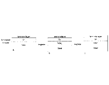
In the context of this invention tinplate is defined as the steel substrate
including the
tin layer, the laminate layer is the polymer coating layer that is to be
laminated onto the
tinplate, and the tinplate with the laminate layer laminated onto the tinplate
is referred to
as the laminated tinplate (see figure 9a-c).
The method according to the invention provides a method to provide a tinplate
sheet,
which may be provided in the form of a strip of tinplate, and provide it with
a laminate
CA 03162200 2022- 6- 16
WO 2021/123312
PCT/EP2020/087228
- 4 -
layer. The surface condition of the tinplate is critical in the adhesion of
the laminate layer
and the method of according to the invention ensures that the surface of the
tinplate is
suitable to be heat-bonded with a laminate layer. The way the surface of the
tinplate is
made suitable is by dipping the tinplate in an aqueous solution, which may be
a buffered
solution, or by imposing a cathodic current onto the tinplate while being
dipped, and
optionally by additionally applying a chromium-free, no-rinse, dry-in-place
passivation
treatment solution to the tinplate sheet. This results in a clean and
susceptible surface
from which any contaminants and tin oxides have been removed to such an extent
that
the adhesion after heat bonding is of the same quality as the adhesion of the
prior art
tinplate that has been passivated with a hexavalent chromium treatment. In
case the
storage conditions of the tinplate are such that substantially no tin oxide
growth takes
place, the surface treatment by dipping the tinplate sheet in the aqueous
solution having
a pH of from 8 to 12 comprising phosphate, borate, sulphate or carbonate ions,
or a
combination thereof, with the optional simultaneous application of a cathodic
current onto
the tinplate may be sufficient and the additional application of the chromium-
free, no-rinse,
dry-in-place passivation treatment solution may not be needed.
Preferably the pH of the aqueous solution is not lower than 8.5 and/or not
higher
than 11.5. A suitable maximum pH value is 11 or even 10.5. The aqueous
solution
preferably contains cations from Group 1 (e.g. Nat, Kt) or Group 2 (e.g. Mg,
Ca2+) from
the Periodic Table or polyatomic cations (e.g. NH4), and polyatonnic anions
(phosphates,
borates, sulphates, carbonates and the like). Also, the anion may be the
conjugate base
of an organic acid (e.g. acetates, citrates). Furthermore, the electrolyte may
contain other
chemical additives, such as surfactants, wetting agents, anti-foaming agents
etc. to
support the electrochemical treatment.
Preferably the aqueous solution contains as the anion only carbonates,
preferably
added to the aqueous solution as sodium carbonate, and preferably no borates,
phosphates, sulphates or the like. By means of a non-limiting example a sodium
carbonate
decahydrate solution, containing not more than 1 g/I Na2CO3.10H20 in deionised
water
with a pH of between 9.5 and 10 is suggested.
However, in case these storage conditions of the tinplate are expected to be
less
favourable because of humidity, storage temperature, storage duration, etc.,
the surface
of the tinplate sheet can be passivated by additionally applying a chromium-
free, no-rinse,
dry-in-place passivation treatment solution to the tinplate sheet, and not by
electrolytic
deposition.
The passivation treatment solution may be based on zirconium, titanium, a
combination of zirconium and titanium, phosphatesõ such as an acidic aqueous
composition containing water-soluble inorganic compounds of the elements Zr,
Ti, Hf as
disclosed in US10011915. Examples are Bonderites M-NT1455, Bonderite M-NT1456
and
CA 03162200 2022- 6- 16
WO 2021/123312
PCT/EP2020/087228
- 5 -
Bonderite M-NT10456 (by Henkel).or Primecoat Z801 (by AD Chemicals). The
passivation
treatment solution is not a silane or siloxane based solution as these do not
improve the
adhesion between the tinplate and the thermoplastic laminate layer in the
context of this
invention. So according to the invention the passivation treatment solution is
silane free,
siloxane free and not Si-based.
Advantages of a no-rinse, dry-in-place system over an electrolytic system is
that the
solutions are simple to apply, use simple equipment in compact application
units, allowing
easy fitting on existing lines and more versatile chemistries are available.
The passivation
treatment solution can be applied to the surface treated tinplate surface by
application
techniques that are common for such passivation systems. Suitable application
techniques
include: dipping, dipping with squeegee rolls, rotor-spray application, rotor-
spray
application supported by the use of a smoothing roll, spray application, spray-
squeegee
application, application by means of a roll coater systems, application by
slot coating, slot
curtain coating, etc.
The surface treated and optionally passivated tinplate can be coiled for
storage and
transport and later uncoiled, or it can be immediately transferred to a
lamination unit where
a laminate layer is laminated in-line onto a pre-heated tinplate.
The invention is also embodied in a method a wherein the thermoplastic
laminate
layer is provided by:
=
providing a pre-produced mono-axially or bi-axially oriented thermoplastic
laminate
layer,
or by
= melting thermoplastic polymer granules in one or more extruders to form
the one or
more layers and forming the thermoplastic laminate layer consisting of the one
or
more layers by passing the molten polymer or polymers through a flat (co-
)extrusion
die and/or two or more calendering rolls;
followed by:
A.
= cooling the thermoplastic laminate layer to form a solid thermoplastic
laminate
layer;
= optionally trimming the edges of the thermoplastic laminate layer;
= reducing the thickness of the solid thermoplastic laminate layer by
stretching the
solid thermoplastic laminate layer in a stretching unit by exerting a
stretching
force only in the longitudinal direction;
= optionally trimming the edges of the stretched thermoplastic laminate
layer;
= laminating of the laminate layer onto the pre-heated tinplate sheet;
or followed by
B.
CA 03162200 2022- 6- 16
WO 2021/123312
PCT/EP2020/087228
- 6 -
= drawing the extruded thermoplastic laminate layer between the flat (co-
)extrusion
die and a cast roll, and cast at its final desired thickness on the cast roll
to rapidly
cool the drawn thermoplastic layer wherein the cast&cooled thermoplastic
laminate layer is essentially non-oriented;
= optionally trimming the edges of the cast&cooled thermoplastic laminate
layer;
= in-line laminating the cast&cooled thermoplastic laminate layer onto the
pre-
heated tinplate sheet.
The application process of the laminate layer to the tinplate is preferably
performed
by means of extrusion coating and lamination, wherein a polymer is melted and
formed
into a thin hot film in a flat (co-)extrusion die, wherein the extruded
polymer film is
subsequently led onto a cast or cooling roll and then laminated onto the pre-
heated tinplate
substrate to form the laminated tinplate. The laminated tinplate then usually
passes
through a roll-nip assembly, which presses the laminate layer firmly onto the
substrate to
ensure complete contact and adhesion. The pre-heat temperature of the tinplate
has to be
sufficiently high to promote adhesion of the laminate layer to the tinplate,
but not so high
as to cause sticking of the laminate layer to the installation or to cause
degradation of the
laminate layer. The optimal pre-heat temperature therefore depends on the
combination
of the laminate layer and the lamination apparatus.
The alternative for extrusion coating and lamination is film lamination, where
a solid
laminate layer is supplied and coated onto a heated tinplate and pressed onto
the tinplate
by a roll-nip assembly to ensure complete contact and adhesion of the laminate
layer to
the pre-heated tinplate. This solid laminate layer may be pre-produced and
even bought
from an external supplier, or it may be produced on-site and subsequently
laminated onto
a tinplate sheet.
In both cases, after laminating the laminate layer onto the tinplate in the
roll-nip
assembly, the laminated tinplate is post-heated in a post-heat device to a
temperature
above the melting point of the laminate layer or layers, or if the laminate
layer consists of
different polymers, to a temperature above the melting point of that laminate
layer in the
multilayer system that has the highest melting temperature. The aim of the
post-heat is
to reduce or eliminate any residual orientation in the laminate layer.
After this post-heat the laminated tinplate is immediately cooled at a
sufficiently high
cooling rate and to a temperature which is sufficiently low to suppress
crystallisation as
much as possible, preferably to completely suppress crystallisation. A water
quench is
adequate and often used. For most polyesters a quench temperature of below 50
C is a
good guideline. Below the glass temperature (Tg) the polymer chains are no
longer mobile.
A value of 50 C is below the glass temperature of most aromatic
(co)polyesters.
Polyolefins have a much lower Tg, even below 0 C, so here the issue is to
suppress
crystallisation as much as possible and in particular avoid the growth of
large (spherulitic)
CA 03162200 2022- 6- 16
WO 2021/123312
PCT/EP2020/087228
- 7 -
crystals. The cooling rate achieved in such a quench is not particularly
critical, as long as
it is fast enough, and a suitable values lies between about 50 to 300 C/s,
e.g. about 100
C/s. The required pre-heat and post-heat temperature and the cooling rate and
cooling
temperature depends on the type of polymer used and can be easily determined
on the
basis of the above. The post-heat temperature is preferably at least 235 C.
As laminate layer the invention can use pre-produced biaxially or monoaxially
oriented polymer films, in-line cast and stretched monoaxially oriented
polymer films, or
in-line cast and drawn unstretched polymer films as claimed in claim 2.
The polyester in the laminate layer is a thermoplastic aromatic (co)polyester
or blend
thereof. In particular reference is made in relation hereto to polyethylene
terephthalate
(PET), IPA-modified polyethylene terephthalate (IPA-PET), CHDM-modified
polyethylene
terephthalate (PETg), polybutylene terephthalate (PBT), polyethylene
naphthalate (PEN),
or copolymers or blends thereof.
The polypropylene in the laminate layer is selected from the group of
polypropylenes,
polypropylene copolymers, chemically modified polyolefins such as maleic
anhydride
grafted polypropylene. The latter is used mainly as an adhesion layer.
Polypropylene is
used mainly as a bulk layer.
In the context of this invention "in-line" is to be understood as constituting
an integral
part of a continuous sequence of operations. Consequently, in an in-line
production of the
laminate layer and the laminated tinplate the production of the laminate
layers and the
coating of the laminate layers onto the pre-heated tinplate is performed in a
continuous
and uninterrupted sequence of operations.
The invention is also embodied in the laminated tinplate wherein the laminate
layer
is formed at least on the side that becomes the inside of a packaging, such as
a container
or can, and the polyester in one or more of the layers in the laminate layer
contains at
least 80 mol.%, and preferably 85 mol.% of an ethylene terephthalate unit or
wherein the
polyester is a co-polyester comprising at most 35 mol.% of CHDM or 20 mol.% of
IPA.
The invention is also embodied in the laminated tinplate wherein the laminate
layer
is formed at least on the side that becomes the inside of a packaging, such as
a container
or can, and the polyester in one or more of the layers in the laminate layer
contains at
least 80 mol.%, and preferably 85 mol.% of a butylene terephthalate unit.
The invention is also embodied in the laminated tinplate wherein the laminate
layer
is formed at least on the side that becomes the inside of a packaging, such as
a container
or can, and the polyester in one or more of the laminate layer contains a
blend of a
polyester containing 85% by mole of an ethylene terephthalate unit and a
polyester
containing at least 85% by mole of a butylene terephthalate unit.
CA 03162200 2022- 6- 16
WO 2021/123312
PCT/EP2020/087228
- 8 -
The invention is also embodied in the laminated tinplate wherein the laminate
layer
or layers on at least one of the sides of a packaging such as a container or
can, comprises
one or more polypropylene layers consisting essentially of polypropylene.
The invention is also embodied in the laminated tinplate wherein the laminate
layer
or layers comprises an adhesion layer consisting of a maleic anhydride grafted
polypropylene.
In another embodiment of the invention the laminated tinplate is subjected to
a
stretching operation wherein the stretching operation is achieved by:
= passing the material through a temper mill and applying a thickness
reduction between
0 - 3%, preferably of at least 0.2%; or by
= passing the material through a stretcher-leveller.
To achieve intimate bonding between the laminate layer and the tinplate it is
necessary to utilise elevated temperatures and/or heat treatments such as the
pre-heating
of the substrate and the postheating of the laminated tinplate. These heat
treatments can
negatively impact the bulk mechanical properties of the steel substrate, due
to ageing
effects. By stretching the polymer-coated steel substrate to a small extent
(i.e. between 0
- 3%, preferably at least 0.2%, more preferably at least 0.5%) through temper
rolling or
passing the material through a stretcher-leveller. Such a treatment improves
the bulk
mechanical, may improve the strip shape and such a material conditioning
process can
also potentially be used to modify the surface structure. The inventors found
that the
development of stress cracking in polymer-coated steel substrates for
packaging
applications is directly related to the mechanical behaviour of the substrate.
There is a
strong correlation between the occurrence of stress racking and the areas
where the
substrate shows inhonnogeneous, localised deformation due to discontinuous
yield
phenomena (LUders lines). By temper rolling or stretcher-levelling the polymer-
coated
substrate these discontinuous yield phenomena are suppressed.
The invention is also embodied in the method wherein the laminate layer on the
one
or both sides of the passivated tinplate sheet is a multi-layer coating
system, said coating
system comprising at least an adhesion layer for adhering to the passivated
tinplate sheet,
a surface layer and a bulk layer between the adhesion layer and the surface
layer.
The method according to the invention involving the production of in-line
casting and
drawing of unstretched polymer films is eminently suitable for producing
laminated tinplate
for 3-piece can bodies as described in W02019110616-A1.
The invention is also embodied in a preferable embodiment wherein the
cast&cooled
thermoplastic laminate layer is slit in the longitudinal direction into at
least N wide laminate
layers (9a-9d), where N is at least 2 and (N-1) narrow strips (10a-10c) using
slitting means
(11), followed by leading the narrow strips away from the wide laminate layers
by
discharging means (12) and subsequently coating the wide laminate layers onto
the pre-
CA 03162200 2022- 6- 16
WO 2021/123312
PCT/EP2020/087228
- 9 -
heated tinplate by means of a nip-roll assembly (4a,4b) to obtain a laminated
tinplate with
a plurality of wide laminate layers (9a-9d) separated spatially in the
longitudinal direction
by narrow strips (10a-10c) free from said wide laminate layer and wherein the
edges of
the tinplate remain free from said wide laminate layer, followed by the post-
heating of the
laminated tinplate and the cooling of the post-heated laminated tinplate.
This embodiment results in a laminated tinplate coated with narrow strips of
thermoplastic laminate layer produced from a single wider thermoplastic
laminate layer
that was produced by in-line extrusion. Between the narrow strips there is a
very narrow
strip of uniaminated tinplate, and the laminated tinplate produced thusly is
particularly
suitable for producing blanks for 3-piece can bodies.
In an embodiment the laminate layer has a thickness of between 5 and 35 pm.
In the method according to the invention the laminate layer is defined in
terms of its
major polymer constituent. However, in addition to the polymer constituents
additives such
as anti-oxidant, heat stabiliser, UV absorbent, plasticiser, pigment,
nucleating agent,
antistatic agent, release agent, anti-blocking agent, etc. may be present in
the polymer.
Co-polyesters are produced when more than one diacid or diol is used in the
polymerisation process. When ethylene glycol (EG) and up to 35%
cyclohexanedimethanol
(CH DM) are used together a co-polyester called glycol modified polyethylene
terephthalate
(PETg) is produced. When up to 20 mol.% of the terephthalic acid is replaced
by isophthalic
acid (IPA), the result is the IPA-PET co-polyester.
Preferably the steel used for the tinplate steel substrate is a carbon steel,
preferably
a low carbon steel, extra-low carbon steel, ultra-low-carbon steel or a HSLA-
steel. The
thickness of the steel substrate is usually between 0.10 and 0.49 mm. These
unalloyed
(ULC, LC and ELC) or micro-alloyed (HSLA) steels are relatively cheap
substrates and
provide good strength and formability. The steels are produced by means of
commonly
known processes such as casting, hot-rolling and cold-rolling. Low carbon
steels typically
comprise 0.05 to 0.15 wt. /0 C and extra low carbon steels typically comprise
0.02 to 0.05
wt.% C. Ultra Low Carbon steels comprise typically below 0.01 wt.% C. Other
elements
may be present in addition to carbon in accordance with EN 10020-2000 which
prescribes
how much of a certain element may be present to still be considered unalloyed
steel.
The invention is also embodied in a laminated tinplate obtained by the process
according to the invention, in the laminated tinplate for producing blanks for
3-piece cans,
and in the use of the laminated tinplate according to the invention in a
process to produce
cans or can parts for packaging purposes.
Examples
The invention will now be explained by means of the following, non-limiting
Examples.
CA 03162200 2022- 6- 16
WO 2021/123312
PCT/EP2020/087228
- 10 -
A cold-rolled low carbon steel of thickness 0.17 mm and TH550 temper grade was
electrolytically tinned on a commercial tinning line to give tinplate having a
tin coating
weight of 1.0, 2.0, 2.8 or 5.6 g/m2 on the test side of the product. In most
cases the tin
layer was flow melted but in two cases (Examples 7 and 8) the flow melting
unit was
switched off to produce non flow melted tinplate. The as-produced tinplate was
subsequently passivated in-line with the tinning process according to
different methods as
outlined below.
In Examples 1 - 6, which reflect the current state-of-the-art, the tinplate
was
passivated by passing the strip through a sodium dichromate solution under
cathodic
current, i.e. the traditional 'CDC' (cathodic dichromate) or '311' passivation
treatment.
In Examples 7 - 10, a chromium-free passivation was applied by first passing
the
strip through a sodium carbonate solution (characterised by a pH of 9.5 - 10)
without
applying a current. After rinsing and drying, a solution of Bonderite M-NT1456
was applied
by means of a spray disc in combination with smoothing rolls. The
concentration of the
Bonderite solution corresponded to 0.25 g/I Ti and was applied at a wet film
thickness of
about 4 ml/m2 aimed to give a dry passivation film thickness of 0.8 - 1.2
mg/nn2 Ti. The
wet film was dried in place and the strip was subsequently coiled.
In Examples 11 and 12, the strip was passed through the sodium carbonate
solution
of Examples 7 - 10 without applying a current. After rinsing and drying, the
strip was coiled
without applying the Bonderite solution. If the time between the passing of
the tinplate
through the sodium carbonate solution and the lamination of the tinplate with
a
thermoplastic laminate layer is brief, then these examples show that without
the
application of a chromium-free passivation treatment solution to the tinplate
good adhesion
can be obtained.
In Examples 13 and 14, the strip was passed through the sodium carbonate
solution
of Examples 7 - 12 while applying an anodic current corresponding to a charge
density of
40 C/m2. After rinsing and drying, a solution of Bonderite M-NT1456 was
applied by means
of a spray disc in combination with smoothing rolls. The concentration of the
Bonderite
solution corresponded to 0.25 g/I Ti and was applied at a wet film thickness
of about 4
ml/m2 aimed to give a dry passivation film thickness of 0.8 - 1.2 mg/m2 Ti.
The wet film
was dried in place and the strip was subsequently coiled.
To the various tinplate materials described above, a polyester coating was
applied by
means of the extrusion coating and laminating process. Two types of polymer
coating were
applied:
= Coating type A consists of a monolayer of 15 pm in thickness consisting
of
poly(ethylene terephthalate) type N180, commercially available from Indorama
(PET)
. Coating type B consist of an adhesion layer, contacting the
metal substrate, of 3 pm
in thickness and a top layer of 12 pm in thickness. The adhesion layer is a
mixture
CA 03162200 2022- 6- 16
WO 2021/123312
PCT/EP2020/087228
- 11 -
consisting of 70% by weight of glycol-modified poly(ethylene terephthalate)
(PETg),
Eastar Copolyester 6763, commercially available from Eastman Chemical Company,
and 30 % by weight of poly(ethylene terephthalate) type N180. The top layer
consists
of poly(ethylene terephthalate) type N180 (PET).
In the polymer coating process, the tinplate was pre-heated to a temperature
such
that the tinplate temperature was at least 170 C when the laminate layer was
brought into
contact with the tinplate. After applying the laminate layer, the laminated
tinplate were
briefly re-heated to a temperature of 275 C, subsequently quenched in a cold-
water tank,
dried, and coiled.
An overview of the different laminated tinplate in the present Examples is
given in
Table 1. Examples 1 - 6 reflect the current state-of-the-art, where the
tinplate substrate
is tinplate passivated with a hexavalent chromium passivation solution (311).
Examples 7
- 12 are the inventive examples where the tinplate substrate is a chromium-
free tinplate.
Examples 13 - 14 are the comparative examples where the tinplate substrate is
a
chromium-free tinplate.
Evaluation of the materials
Dry adhesion by 180 T-peel test
A quantitative evaluation of coating adhesion was done by 180 T-peel tests
performed on flat sheet material. For this test, 15 mm wide strips were cut
from the
polymer-coated material. The strip was placed with the narrow end in a small
volume of
18% hydrochloric acid to etch the steel base and obtain a short length (a few
mm) of free
polymer coating. Adhesive tape was attached to the free coating, and the
coating was
subsequently peeled away from the substrate at a 180 angle using a tensile
tester
operated at 25 mm/min. The T-peel force is measured as the maximum load value
(expressed in N/15mm) required to start peeling off process.
Dry adhesion by cross-cut test
Coating adhesion on flat material was evaluated using a cross-cut test
according to
ISO 2409. A special cutting tool, consisting of 4 cutting blades spaced 5 mm
apart, was
used and the cross-cut was applied to a 15 x 7.5 cm flat panel using a
laboratory scale,
motor-driven cutting apparatus. After application of the cross-cut, coating
adhesion is
evaluated by peeling the coating using a piece of 25 mm wide, Scotch No. 610
adhesive
tape, and expressing the result by the well-known Gitterschnitt (GT) scale
ranging from 0
(no delamination) to 5 (total delamination). All tests are done in triplo.
Adhesion after sterilisation in various media
Flat panels of 15 x 7.5 mm in size were placed in a test medium inside a
CertoClav
"pressure cooker" sterilisation apparatus, and the appropriate time and
temperature
CA 03162200 2022- 6- 16
WO 2021/123312
PCT/EP2020/087228
- 12 -
conditions for sterilisation were then applied. The various media and test
conditions are
described in Table 2. After the sterilisation procedure, the panels were
allowed to cool and
dry, and adhesion was evaluated (within less than 4 hours) by the cross-cut
test as
described above.
XPS (X-ray photoelectronic spectroscopy) analysis of delamination interface
Surface and near surface chemical analysis of freshly delaminated samples was
carried out by means of a Kratos Axis Ultra instrument, using Al
monochronnated source
(1486.7 eV) at 15 kV acceleration voltage and 15 nnA emission current. The
subsurface
composition of the freshly exposed surfaces was investigated by XPS depth
profiling using
Ar+ sputtering. After each XPS measurement the sputtering cycle was done at 2
kV of
acceleration voltage and 60 pA extraction current of 3x3 mm sputter area that
delivers a
sputtering speed of 1 nnn/nnin. The analysis was performed on substrate and
coating side
of the freshly delaminated surfaces. Dela mination was achieved by applying an
epoxy resin
(Betamate 1496) to a sample of polymer-coated metal followed by curing at
about 175 C
for 20 min, and subsequently dipping the sample in liquid nitrogen, where
relatively thick
epoxy layer pulls the polymer coating off from the substrate due to epoxy
shrinkage at low
temperature. XPS analysis was performed at room temperature in ultra-high
vacuum (1 x
10-9 mbar) to mitigate the effect of the atmosphere. The obtained XPS spectra
per detected
element were then processed using CasaXPS to produce concentrations (atomic %)
of
different species at different depth from the surface.
Evaluation of adhesion on polymer-coated tinplate by means of the cross-cut
test is
always done using at least three panels, and due to the nature of the test and
interpretation
of the result, there may be a small variation in the GT adhesion value between
separate
panels. Based on our experience we have established that adhesion of the
polymer coating
on tinplate substrates will be sufficient for final end-use applications as
long as the highest
GT adhesion value (i.e. poorest adhesion result) is not higher than 2 within
the three tested
panels. Furthermore, the dry T-peel adhesion value should be at least 5 N/15mm
in order
to undergo forming steps without delannination of the coating.
Adhesion results from the present Examples are given in Table 4. Based on the
above
criteria, it is seen that the materials according to present state-of-the-art,
using chromium
passivation, all show good performance. For coating type A, dry T-peel
adhesion values
are in the range from 8 to 11 N/15mm, while for coating type B the values are
in the range
from 6.5 to 8.5 N/15mm. Furthermore, cross-cut adhesion values are all within
the
required range. The tin coating weight of the tinplate substrate does not
appear to have
any significant effect on the test results within the investigated range.
The Inventive Examples 7 - 12 also demonstrate excellent adhesion properties
with
dry T-peel adhesion values (coating Type B only) in the range from 7 to 9
N/15nnnn and
cross-cut adhesion values ranking 2 or lower in all cases. Interestingly, when
no Bonderite
CA 03162200 2022- 6- 16
WO 2021/123312
PCT/EP2020/087228
- 13 -
passivation solution is applied after the cleaning step (Ex. 11 and 12),
excellent adhesion
is also achieved. It should be noted that in this case, which corresponds
essentially to 'non-
passivated' tinplate, a tin oxide layer may form on the outermost surface of
the tinplate
during the time elapsed between production of the tinplate material and
coating with a
polymer layer, and that this tin oxide layer could impair the adhesion of the
polymer
coating. So, when using this method, the time elapsed between production of
the tinplate
material and coating with a polymer layer, and the conditions of storage of
the tinplate
material (e.g. temperature, relative humidity) should be well controlled.
In the Comparative Examples 13 ¨ 14, where the cleaning step is performed
using
an anodic current, very poor coating adhesion is observed. The dry T-peel
adhesion values
are very low (2.0 N/15mm in Ex. 13) or difficult to measure (< 0.5 N/15mnn in
Ex. 14,
where the coating almost spontaneously delaminated from the substrate), and
this is
similarly noticed in cross-cut adhesion values ranking 3 in many cases, and
even up to 4
or 5 in the most aggressive media, i.e. media containing acetic acid.
Analysis of the delamination interface by XPS reveals that the poor adhesion
in the
Comparative Example 14 can be attributed to the presence of tin oxide species,
mainly
5n07, at the interface between polymer and tin layer. Figures 4 and 5 show the
XPS depth
profiles of the tinplate substrate and the peeled-off polymer coating,
respectively, for
material from Example 4, representing the state-of-the-art chromium-passivated
tinplate.
On both the substrate side and the delaminated polymer side, the depth profile
shows
predominantly organic carbon. This means that delamination of the polymer
coating occurs
through cohesive failure within the polymer itself, at some distance (several
tens of
nanometres) away from the tin surface. This implies that the adhesion between
the
polymer and the tin surface is very strong. Figures 6 and 7 show the XPS depth
profiles of
the tinplate substrate and the peeled-off polymer coating, respectively, for
material from
Inventive Example 8, representing chromium-free passivated tinplate, involving
the steps
of cleaning in sodium carbonate solution without applying a current and
subsequently
applying a Bonderite M-NT1456 solution. On the substrate side, the depth
profile shows
predominantly tin with a very thin layer (about 1 nnn) of tin oxide, mainly
SnO. This thin
SnO layer may have been formed in the sample preparation process after
separation of
the polymer coating. On the peeled-off coating side, predominately organic
carbon is
observed. This result indicates that delamination takes place on a well-
defined interface
between the organic coating layer (i.e. the organic portion of the Bonderite
layer and/or
the polymer coating layer) and tin, providing a strong bond between coating
and substrate
as reflected in a high T-peel adhesion force and good adhesion performance in
the cross-
cut test. Finally, Figures 8 and 9 show the XPS depth profiles of the tinplate
substrate and
the peeled-off polymer coating, respectively, for material from Comparative
Example 14,
representing chromium-free passivated tinplate, involving the steps of
cleaning in sodium
CA 03162200 2022- 6- 16
WO 2021/123312
PCT/EP2020/087228
- 14 -
carbonate solution while applying an anodic current and subsequently applying
a Bonderite
M-NT1456 solution. The depth profiles on both the substrate side and the
polymer side
show significant amounts of tin oxide, mainly Sn02, of several nanonnetres in
thickness.
The fact that tin oxide is clearly present of both sides of the delamination
interface means
that delamination occurs within the oxide layer. From the T-peel adhesion
values it is
evident that this oxide layer is weak and leads to easy delamination of the
polymer coating
from the tinplate surface. Thus, the presence of such an oxide layer must be
avoided in
order to achieve a good adhesion between the polymer coating and the tinplate
substrate.
Table 1. Properties of tinplate substrate, passivation type and polymer
coating in the
Examples of the present invention (soda = sodium carbonate)
Example Tin Flow Passivation Step 1 Passivation
Polymer
weight melting Step 2
coating
(g/m2)
1* 2.0 Yes None 311 A
2* 2.8 Yes None 311 A
3* 2.0 Yes None 311 B
4* 2.8 Yes None 311 B
5* 1.0 Yes None 311 B
6* 5.6 Yes None 311 B
7 2.0 No Soda, no current Bonderite B
8 2.8 No Soda, no current Bonderite B
9 2.0 Yes Soda, no current Bonderite B
10 2.8 Yes Soda, no current Bonderite B
11 2.0 Yes Soda, no current None B
12 2.8 Yes Soda, no current None B
13* 2.0 Yes Soda, anodic current Bonderite B
14* 2.8 Yes Soda, anodic current Bonderite B
Table 2. Product evaluation tests
Test Description Medium Conditions
Test 1 Dry adhesion n/a
n/a
Test 2 Bouillon Plasma! 12 g/I Maggi + 2g/I Plasma!
121 C / 90 min
Test 3 Acetic Acid 1% Acetic Acid
121 C / 60 min
Test 4 Saline Test 3.6% NaCI
121 C / 90 min
Test 5 Vitamin C 1 g/I Vitamin C + 3.6% NaCI
121 C / 90 min
Test 6 Water Demineralized water
121 C / 60 min
Test 7 Salt-Acid 18.7 g/I NaCI + 30 g/I acetic acid
121 C / 60 min
As part of the inventors extensive investigations into the surface treatments
of
tinplate in relation to tin oxide formation and stability, and with respect to
adhesion of
organic and polymer coatings, the inventors have studied the performance of
broadly two
types of chromium-free passivation treatment solutions: those based on
siloxanes and
those based on zirconium and titanium compounds. A well-known example of a
siloxane-
based treatment system is Oxsilan MM0705 from Chemetall. A well-known example
of a
CA 03162200 2022- 6- 16
WO 2021/123312
PCT/EP2020/087228
- 15 -
zirconium/titanium-based treatment system is BonderiteTM M-NT1456 from Henkel.
Both
systems were applied to tinplate having a tin coating weight of 2.8 g/m2 Sn on
both sides
using a spray application installed at a commercial production line. The
application
conditions and chromium-free passivation treatment solution composition was
chosen to
give a treatment layer thickness of 0.6 - 0.8 mg/m2 Si or Ti, afterwards
confirmed by
surface characterisation (XP5). Tin oxide and tin oxide growth rate was then
determined
and compared to chromium passivated ('311') tinplate and non-passivated
tinplate.
The amount of tin oxide present on the surface of the material can be
determined
using a coulometric method. The tin oxide layer is reduced by a controlled
small cathodic
current in a 0.01M solution of hydrobromic acid (HBr) that is freed from
oxygen by
scrubbing with nitrogen. The progress of the reduction of the oxide is
monitored by
measuring the reduction potential, and the charge passed (A*t) for the
complete reduction
serves as a measure of the tin oxide layer thickness. For the test, a
cylindrical cell is used
having a circular aperture of ca. 4 cm diameter on one end and an Ag/AgCI
reference
electrode. The other end of the cell contains a platinum counter electrode.
The test
specimen covers the aperture, which is sealed using an 0-ring to make a water-
tight
connection of a well-defined area, and is tightened into place using an air-
pressure
cylinder. The cell is connected to the electrolyte solution by a flexible tube
so that it can
be filled and emptied under nitrogen atmosphere. A cathodic current density of
-0.50 A/nn2
is applied to the sample using a potentiostat-galvanostat, and the potential
is measured
until the reduction is complete. The result of the test is expressed as the
total charge
density (in C/nn2) needed to reduce the oxide layer. The stability of the
oxide layer is
examined by placing a test panel in a climate chamber at 40 C and 80% relative
humidity
for two weeks, and then measuring the amount of tin oxide present on the
surface and
comparing to the amount of tin oxide present on the surface in the as-received
tinplate
material.
The results of this investigation are summarised in Table 3. The Zr/Ti-based
Bonderite system provides thinner and more stable tin oxide layers on the
tinplate surface
compared to the Si-based Oxsilan system. Based on this result it is evident
that the Zr/Ti-
based system is ideally suited in terms of the present invention while the Si-
based system
is not.
Table 3. Comparison of tin-oxide layer stability after passivation
Treatment system Tin oxide value (C/m2)
As-received After humid test**
Difference
311 passivation 13 13 0
Bonderite M-NT1456 16 22 6
Oxsilan MM0705 35 86 51
Non-passivated 32 99 67
** Exposed during two weeks at 40 C and 80% RH in a climate chamber
CA 03162200 2022- 6- 16
n
>
o
IA
,
o
rs)
" o
o
r.,
o
r.,
9,
" Table 4. Adhesion values from cross-cut test on flat panels, dry
and after sterilisation in various media, in triplo
Example 1* 2* 3* 4*
5* 6* 7 0
Tin weight (g/m2) 2.0 2.8 2.0 2.8
1.0 5.6 2.0 w
o
w
Flow melted? Yes Yes Yes Yes
Yes Yes No
,
i--,
Passivation Step 1 None None None None
None None Soda
c.a
No current
c.a
1-,
b.)
Passivation Step 2 311 311 311 311
311 311 Bonderite
Coating type A A B B
B B B
Dry adhesion by 1-peel adhesion force 8.6 10.9 6.6 8.3
6.8 8.5 8.0
(N/15 mm)
Test 1. Dry adhesion 1 1 1 1 1 1 1 1 1 1 1 1
1 1 1 1 1 1 0 1 1
Test 2. Bouillon Plasma! 1 1 1 1 1 1 1 1 1 1 1 1
1 1 1 1 1 1 1 2 1
Test 3. Acetic Acid 1 1 1 1 1 1 1 1 1 1 1 1
1 1 1 1 1 1 2 2 2
Test 4. Saline Test 1 1 1 1 1 1 1 1 1 1 1 1
1 1 1 1 1 1 1 2 2
Test 5. Vitamin C 1 1 1 1 1 1 1 1 1 1 1 1
1 1 0 1 1 1 2 2 1
Test 6. Water 1 1 1 1 1 1 0 0 1 1 1 1
1 1 1 1 1 1 1 1 2
Test 7. Salt-Acid 1 1 1 1 1 1 1 1 1 1 1 1
1 0 1 1 1 1 1 2 1
Example 8 9 10 11
12 13* 14*
Tin weight (g/m2) 2.8 2.0 2.8 2.0
2.8 2.0 2.8
Flow melted? No Yes Yes Yes
Yes Yes Yes
Passivation Step 1 Soda Soda Soda Soda
Soda Soda Soda
No current No current No
current No current No current Anodic current Anodic current
Passivation Step 2 Bonderite Bonderite
Bonderite None None Bonderite Bonderite
Coating type B B B B
B B B
Dry adhesion by 1-peel adhesion force 8.7 7.0 7.5 7.2
7.8 2.0 < 0.5
(N/15 mm)
Test 1. Dry adhesion 1 1 1 2 1 1 2 1 1 1 1 1
1 1 1 2 3 2 2 3 3 t
n
Test 2. Bouillon Plasma! 0 1 0 1 1 2 0 1 0 2 1 2
0 1 1 3 3 3 3 3 3 1-3
tt
Test 3. Acetic Acid 2 2 2 2 2 2 2 2 2 2 2 1
2 2 2 5 5 5 5 5 5 it
w
Test 4. Saline Test 1 1 2 1 2 2 1 2 2 1 0 1
1 0 0 2 2 2 2 2 2 o
b.)
o
Test 5. Vitamin C 1 1 1 1 1 1 1 2 1 1 1 0
0 1 1 2 3 3 2 3 3 ,
o
oe
Test 6. Water 1 1 2 1 2 2 1 2 2 1 1 2
1 1 0 2 2 3 2 2 2 --4
b.)
r..)
Test 7. Salt-Acid 1 1 2 1 1 2 1 2 2 1 1 1
2 1 1 4 4 3 444 oe
*comparative examples
WO 2021/123312
PCT/EP2020/087228
- 17 -
Brief description of the drawings
The invention will now be explained by means of the following, non-limiting
figures.
Figure 1 shows the definition of some terms.
Figure 2 shows a schematic depiction of the solid film lamination process.
Figure 3 shows a schematic depiction of the cast film lamination process.
Figures 4 to 9 show XPS profiles of laminated tinplate after separation of the
laminate
layer from the tinplate to study the nature of the bond between the laminate
layer and the
tinplate.
Figure 10 to 12 show the production stages of laminated tinplate for 3-piece
cans.
In Figure 2 the tinplate sheet or strip (1) is passed through first heating
device (2)
where temperature of the tinplate is raised to pre-heat temperature suitable
for lamination,
Ti. Two coils of laminate layer (3a, 3b) are simultaneously unwound and
passed, together
with the pre-heated tinplate, through a roll-nip assembly comprising a pair of
laminating
rollers (4a, 4b). The laminated tinplate (5) is passed through a second
heating device (6)
where the temperature of the laminated tinplate is raised to a post-heat set-
point, T2. After
the second heating device, the laminated tinplate is immediately cooled by
passing through
a quenching device (7) to reach room temperature. The method of pre-heating
the tinplate
in the first heating device is not particularly limited and may include
passing the strip over
heated rolls, conductive heating, inductive heating, radiative heating, etc.
The method of
post-heating the laminated tinplate in the second heating device is preferably
a contactless
method, such as heating in a hot gas environment or inductive heating. The
method of
immediate cooling in the quenching device is not particularly limited and may
include applying
cold air or passing through a cold water bath etc. In figure 2 the laminate
layers are provided
on a coil. However, the laminate layers may also be provided directly from the
extrusion die
after having been stretched and cooled to a solid and stretched thermoplastic
laminate layer.
In Figure 3 the laminate layer is extruded from a flat die (14), drawn down in
a narrow
gap formed between the extrusion die and the cast roll, and cast at its final
desired thickness
on the cast roll (13) where it is rapidly cooled. Since the draw down to the
final thickness
takes place in the liquid condition, the cast laminate layer is essentially
non-oriented. The
laminate layer can then be laminated onto the tinplate 1 in a similar way to
the process
depicted in figure 2.
To produce material for 3-piece cans the extruded laminated layer is slit (11)
and the
narrow polymer strips (10a-10d) in between the wide laminate layers (9a-9d)
are led away
and removed. The number of wide laminate layers (9a-9d) produced from the
extruded
polymer film can be 2 or more. In the explanatory figures a number of four
wide laminate
layers (9a-9d) is used by means of example, but the invention works just as
well with two,
three or more wide polymer films. The number of narrow polymer strips (10) cut
out from
between the wide laminate layers (9a-9d) to be discharged is in principle
always 1 lower than
CA 03162200 2022- 6- 16
WO 2021/123312
PCT/EP2020/087228
- 18 -
the number of wide laminate layers to be laminated onto the tinplate. The
width of the
extruded laminate layer (3) should be smaller than that of the tinplate to
allow the edges of
the tinplate to remain uncoated. If the polymer film becomes too wide for the
edges of the
tinplate to remain uncoated (i.e. bare) then an in-line trimming of the edges
of the polymer
film may be needed. These cut-off edges are led away from the laminate layer
and the
laminate layer is coated onto the tinplate in the lamination process leaving
the outermost
edges of the tinplate bare from polymer. This is preferable over the
alternative namely to
coat the edges and grind off or otherwise remove the edges of the polymer
coating after the
lamination process. The leading away of the cut-off edges of the polymer film
can be done by
a cutting waste extraction device means such as by a sucking device (12).
Figure 10 shows the tinplate 1 in a top view (not to scale) as well as the
extruded and
cooled laminate layer 3. The slit situation is depicted in the bottom drawing
of figure 10 where
the small strips to be removed are hatched (10a-10c) and the wide laminate
layers to be
laminated onto the tinplate with 9a-9d. Figure 11 shows a top view of the
laminated tinplate,
where the bare strips and bare edges are shown. These bare edges and bare
strips are needed
for forming three-piece can bodies which are welded together. Figure 11 also
shows
schematically (top drawing left hand side, dashed lines) how the laminated
tinplate could be
slit lengthwise into four narrow laminated tinplate strips, and also how
individual blanks for
3-piece cans could be produced. Each of these blanks have edges which are free
from
polymer, and are thus weldable to produce a 3-piece can body (see figure 13).
The bottom picture in figure 11 shows a cross section along A-A. Figure 12
shows the
same where laminate layers are provided on both sides of the tinplate. Figure
13 shows a
cross-section of a welded 3-piece can body and the left hand side of the
figure shows an
enlarged portion of the welded portion. The bare tinplate edges are clearly
shown as well as
the edges of the wide polymer film strip 3a and the portion where the two bare
edges are
bonded together by welding. The welded and bare metal is subsequently covered
with a
lacquer 17 to protect the metal against corrosion. The lacquer is preferably
BPA-free.
CA 03162200 2022- 6- 16