Note : Les descriptions sont présentées dans la langue officielle dans laquelle elles ont été soumises.
CA 03162550 2022-05-20
WO 2021/105785 PCT/IB2020/059518
1
PRECISION PLANNING, GUIDANCE AND PLACEMENT OF
PROBES WITHIN A BODY
BACKGROUND
1. Field of the Disclosure
The present disclosure generally relates to guided navigation of devices
such as probes to sites within a body and the system therefor.
2. Discussion of the Related Art
Focal heat destruction or focal hyperthermia is a medically accepted
method of treatment for many types of tumors. Focal heat destruction devices
may
include radiofrequency energy sources, lasers, microwave energy sources, and
high-intensity focused ultrasound energy sources. The energy is delivered to
the
tumors in a minimally invasive manner to achieve tumor destruction without
significant damage to the healthy surrounding tissue. The delivery device or
probe
inserted into the tumor will vary depending on the type of energy source. Long-
term survival is achievable with this form of treatment and thus represents a
viable
alternative to open surgical intervention as well as in cases where tumor
removal
is not an option.
In radio frequency ablation, electromagnetic energy with frequencies of less
than 900 kHz is utilized to generate heat. Radio frequency devices typically
operate in the range of between 375 to 500 kHz. In radio frequency ablation,
electrode probes are placed within the tumors and alternating high-frequency
current displaces molecules within the tumor resulting in localized heating up
to
about 90 degrees C. In laser ablation, a laser is utilized to deliver infrared
light with
a wavelength between 800 and 1100 nm to the tumor. The laser light is absorbed
by tissue-specific chromophores and photon energy is converted into heat to
CA 03162550 2022-05-20
WO 2021/105785 PCT/IB2020/059518
2
produce thermal damage to the target tissue. With laser ablation localized
heating
of between 50 to 100 degrees C is achievable at the desired power setting for
the
laser. In microwave ablation, a microwave source, devices capable of
generating
energy with frequencies greater than or equal to 900 kHz, is utilized to
produce
electromagnetic radiation that relates to the tumors by an antenna in needle
form.
This energy produces rapid agitation of the water molecules within the cells
of the
tumors to cause heating. At the desired power setting, localized heating to
temperatures in the range of 60 to 100 degrees C is achievable. Ultrasound
energy may be applied to tumors by extracorporeal or direct needle/probe
.. application for thermal ablation of the tumors. Ultrasound devices at
frequencies
between 0.8 and 1.6 MHz can deliver narrow focus energy to target tissue after
harmlessly passing through soft tissue. This energy is absorbed in the target
tissue where it is converted into heat raising the temperature of the tissue
at the
target site to greater than 80 degrees C. With ultrasound, two mechanisms of
action are at work; namely, the thermal energy damage as described above, and
mechanical damage due to vibration of the tissue via acoustic cavitation.
What makes this type of therapy effective is cancer cells have an increased
sensitivity to heat as compared to normal cells and thus may be destroyed with
minimal or no damage to healthy tissue. Damage to the target tissue or tumor
occurs in two distinct phases, direct heat injury and indirect injury. Direct
thermal
injury is determined by the total energy applied to the tumor, tumor biology
and
tumor microenvironment. Indirect thermal energy occurs after the application
of
energy has stopped. It is the damage that progresses after the application of
energy has ceased. The progressive damage depends on a number of factors
including microvascular damage causing endothelial cell damage, ischemia-
reperfusion injury, apoptosis or cell death, altered cytokine expression and
immune response. All of these progressive factors result in further damage to
the
cancerous tissue.
CA 03162550 2022-05-20
WO 2021/105785 PCT/IB2020/059518
3
As stated above, the survival rates for patients undergoing focal heat
destruction rivals those undergoing surgical resection in a significant number
of
cases; however, reoccurrence of the cancer is much more likely to occur in
cases
of incomplete destruction of the tumor. In order to completely eradicate a
tumor,
.. the entire tumor must be heated to a temperature that will destroy the
cells.
Accordingly, several factors should preferably be considered. One factor to
consider is the size and geometry of the tumor(s). Typically, these procedures
are
done percutaneously and are thus visualized under fluoroscopy in two-
dimensions.
CT imaging can be used to view two-dimensions slices of a patient's anatomy
and
the tumor's geometry; however, compiling these slices to accurately gauge the
complex geometry of a given tumor remains a challenge. This may not give the
physician an accurate sense of geometry or size. In addition, the probe or
probes
inserted into the tumor utilizing this method may not be accurately positioned
by
simply viewing it in two-dimensions. Another factor to consider is the
surrounding
tissue, including critical anatomy. With two-dimensional imaging, various
anatomical features may not be captured. Yet another factor to consider is
heat
sinking anatomical features. If heat is drawn off the target tissue by
surrounding
healthy heat sinking tissue, the required temperature to destroy the cancerous
tissue may not be achieved. Still yet another factor to consider is
electromagnetic
.. wave cancellation. If more than one probe is utilized to radiate the
energy,
incorrect placement may result in partial or complete phase cancellation. This
phase cancellation will result in less energy reaching the target tissue and
thus
may result in incomplete destruction of the tumor.
Accordingly, improvements are needed.
SUMMARY OF THE DISCLOSURE
The present disclosure relates to a method for navigating a probe to a
location within a body of a patient. The method and system of the present
disclosure overcomes a number of the limitations associated with the prior art
as
CA 03162550 2022-05-20
WO 2021/105785 PCT/IB2020/059518
4
briefly described above. The method comprising the steps of visualizing a
three-
dimensional image of a region of a body of a patient, selecting a target
location
within said three-dimensional image of a region of a patient's body,
determining
and visualizing a preferred pathway for the probe to follow from an external
entry
point on the patient's body to the target location, registering the three-
dimensional
image to the current actual position of the corresponding region of the
patient's
body, registering the current actual position of the probe to the three-
dimensional
image and the current actual position of the patient's body, visualizing the
calculated preferred pathway for the probe simultaneously with the current
actual
position of the probe in real time, aligning the current actual position of
the probe
with the preferred pathway and entry point, advancing the probe into the
patient's
body along the preferred pathway, and updating and visualizing the alignment
of
the probe in real time as the probe is advanced until reaching the target
location.
In accordance with another aspect, the present disclosure relates to a
system for navigating a probe to a location within a body of a patient. The
system
comprising a three-dimensional image of a region of the body of the patient, a
probe configured to be registered to the patient's body position in three-
dimensional space, a registration system to register the current actual
position of
the probe and the patient's body to the three-dimensional image of a region of
the
body of the patient, an imaging device for capturing real-time images of the
region
of the body of the patient, a computational machine for calculating a
preferred
pathway of the probe to a target location within the region of the body of the
patient and in communication with the imaging device and registration system,
and
a display for visualizing the real-time images from the imaging device and the
three-dimensional alignment of the current actual position of the probe and
the
patient's body relative to the preferred pathway and the target location.
CA 03162550 2022-05-20
WO 2021/105785 PCT/IB2020/059518
BRIEF DESCRIPTION OF THE DRAWINGS
The foregoing and other features and advantages of the disclosure will be
5 apparent from the following, more particular description of preferred
embodiments
of the disclosure, as illustrated in the accompanying drawings.
Figures 1A-1C are diagrammatic representations of a pre-procedure scan
of a patient, the patient and a holographic overlay of the pre-procedure scan
overlaid on the patient in accordance with the present disclosure.
Figure 1D is a diagrammatic representation of registration markers on a
patient and an image of a patient with the registration markers in accordance
with
the present disclosure.
Figure 2 is a diagrammatic representation of a human liver with a tumor and
surrounding anatomical structures.
Figure 3A is a diagrammatic representation of the human liver with a tumor
of Figure 2 at a first time associated with an initial scan in accordance with
the
present disclosure.
Figure 3B is a diagrammatic representation of the human liver with a tumor
of Figure 2 at a second time associated with a second scan in accordance with
the
present disclosure.
Figure 4 is a diagrammatic representation of multiple ablation probes and
associated ablation regions within a tumor.
Figure 5 is a diagrammatic representation of the heat sink effect for an
ablation probe within a tumor.
CA 03162550 2022-05-20
WO 2021/105785 PCT/IB2020/059518
6
Figure 6A is diagrammatic representations of a single ablation probe
trajectory in accordance with the present disclosure.
Figures 6B and 60 are diagrammatic representations of the methods of
visualization for the calculated path of Figure 6A in accordance with the
present
disclosure.
Figure 7 is a diagrammatic representation of a calculated trajectory
projection based on real-time location of the ablation probe in accordance
with the
present disclosure.
Figures 8A- 80 are diagrammatic representations of the introduction sheath
system of the present disclosure.
Figure 9 is a diagrammatic representation of an exemplary feedback
mechanism in accordance with the present disclosure.
Figure 10 is a diagrammatic representation of an exemplary ablation probe
in accordance with the present disclosure.
Figure 11A-11F show diagrammatic representations relating to example
methods for determining a preferred pathway from a three-dimensional image of
a
region of the body.
DETAILED DESCRIPTION OF THE PREFERRED EMBODIMENTS
Systems and methods are described for navigating a probe to a location
within a body of a patient. The probe may comprise a needle, introducer,
catheter,
stylet, or sheath. Other probes may be used. Methods may comprise visualizing
a
three-dimensional image of a region of a body of a patient. As an example, the
CA 03162550 2022-05-20
WO 2021/105785 PCT/IB2020/059518
7
three-dimensional image of a region of a body of a patient may be based on one
or more of magnetic resonance imaging (MRI), computer tomography (CT), or
ultrasound. Other imaging techniques may be used. Methods may comprise
receiving a selection of a target location within said three-dimensional image
of a
region of a patient's body. As an example, the receiving a selection of a
target
location is via interaction with a display device configured to output one or
more of
the visualizing steps. Other inputs may be used to effect selection. Methods
may
comprise determining and visualizing a preferred pathway for the probe to
follow
from an external entry point on the patient's body to the target location. The
preferred pathway may be determined by transforming a selected point in a two-
dimensional view of the three-dimensional image of a region of a body of a
patient
into a line (e.g., line of sight) through the three-dimensional image of a
region of a
body of a patient. Methods may further comprise calibrating the preferred
pathway
to compensate for shift of anatomical structures pre-operatively.
Alternatively or
additionally, methods may further comprise calibrating the preferred pathway
to
compensate for shift of anatomical structures intra-operatively. Methods may
comprise registering the three-dimensional image to the current actual
position of
the corresponding region of the patient's body. Methods may comprise
registering
the current actual position of the probe to the three-dimensional image and
the
current actual position of the patient's body. Methods may further comprise
updating the registration of the three-dimensional image to the patient to
compensate for shift of anatomical structures. Methods may comprise
visualizing
the preferred pathway for the probe simultaneously with an indication of the
current actual position of the probe in real time such that the simultaneous
visualizations enables a user to align the current actual position of the
probe with
the preferred pathway. As an example, the indication of the current actual
position
of the probe comprises the position of the probe in three-dimensional space.
As a
further example, the indication of the current actual position of the probe
comprises the projected extension of the probe in three-dimensional space.
Methods may comprise updating and visualizing an indication of the current
actual
position of the probe in real time as the probe is advanced to the target
location.
CA 03162550 2022-05-20
WO 2021/105785 PCT/IB2020/059518
8
Additionally, output of an auditory or visual feedback may be used to warn the
user
about information regarding proximity to the target location and/or to warn
the user
about information regarding proximity to critical anatomical structures.
Ablation of anatomical material such as tumors is used herein as an
illustrative example. Other processes and procedures may benefit from the
systems and methods as described herein. Focal heat destruction or ablation is
an
important therapeutic strategy for treating certain tissues such as benign and
malignant tumors. As set forth above, there are a number of energy sources
that
may be utilized, and each has its advantages and disadvantages. Radio
frequency
ablation is widely utilized and there are a number of radio frequency-based
devices and power supplies that are currently utilized. However, radio
frequency
energy has several limitations, including the rapid dissipation of energy in
surface
tissues resulting in shallow "burns" and failure to access deeper tumor
tissues.
Another limitation associated with radio frequency ablation systems is the
tendency of eschar (slough) and clot formation to form on the energy emitting
electrodes which in turn limits the further deposition of energy.
Given the limitations associated with radio frequency ablation, microwave
ablation offers a viable and effective alternative. More specifically,
microwave
energy provides for deeper tissue penetration, an insensitivity to charring, a
lack of
necessity for grounding, more reliable energy deposition, faster tissue
heating and
the capability to produce much larger thermal lesions than radio frequency
ablation. There are a number of devices that utilize electromagnetic energy in
the
microwave frequency range as a means for focal heat destruction or ablation.
The present disclosure relates to a method and system for navigating one
or more probes to a location within a body of a patient. The present
disclosure
relates to a method of and associated system for determining an accurate three-
dimensional model of a tumor and its surrounding environment, inclusive of
anatomical structures, as well as a means for automatically calculating the
number
CA 03162550 2022-05-20
WO 2021/105785 PCT/IB2020/059518
9
of energy radiating probes and their respective positioning/trajectory
specifics of
the energy radiating probes within the tumor(s) to ensure no destructive
interference of the radiating energy in the patient and the complete
eradication of
the targeted cancerous cells. To achieve optimal trajectories for each probe
utilized to ensure complete tumor destruction, the methodology of the present
disclosure includes predictive analytics which account for the effects of
tissue
shrinkage due to electro-magnetic radiation exposure. Although, as set forth
above, there are several energy sources available, exemplary embodiments of
the
present disclosure will be described with respect to a system for the delivery
of
microwave radiation as a means for focal heat destruction. An exemplary system
is described in United States Patent Publication Number 2018/0132934, assigned
to NeuWave Medical, Inc.
As an illustrative example, optimum trajectories of probes (e.g., ablation
probes or other probe devices), which may be determined (e.g., calculated)
based upon anatomical geometry obtained from a variety of pre-procedural
imaging modalities, including magnetic resonance imaging (MRI), computer
tomography (CT) and ultrasound, may be calibrated to the patient in real-time
to
account for internal shifting of anatomical structures within the body between
the
time of imaging and the time at which the patient is prepped and positioned on
the operating or procedure table.
As a further example, calibration maybe accomplished by mapping the pre-
procedural imaging, for example, CT scans, and the predetermined directional
surgical path vectors that indicate the determined optimum trajectories of the
probes through the body onto the patient via anatomical markers, vision
systems,
and/or markers placed onto the patient's body. Similar processes are utilized
in
numerous procedures, for example, guided sinus surgery utilizing masks. The
location and orientation of the surgical path vector as well as the anatomical
features (e.g., tumor(s)) of interest may then verified using, for example, an
ultrasound probe in real-time.
CA 03162550 2022-05-20
WO 2021/105785 PCT/IB2020/059518
As an illustrative example, once this is accomplished, the physician, an
artificial intelligence (Al) module of the software implementing the
methodology of
the present disclosure in conjunction with an ablation system, and/or the
5 physician guided by the Al may then tag and record discrete slices of the
tumor
and the surgical path vector as the fan beam of the ultrasound probe is passed
across the both the surgical path vector and the full target tumor. As the
ultrasound records the position of the tumor and other relevant anatomical
structures in the surrounding space, the Al/software automatically adjusts the
CT-
10 overlay to match the patient's real-time anatomy via a three-
dimensional, line-of-
best fit optimization, and subsequently adjusts the optimized surgical path
vector
for ablation probe trajectories to account for any anatomical shifting that
may
have occurred since the initial formulation of the trajectories that may have
been
based on historical imaging data. The ablation system described herein may
also
incorporate an augmented reality (AR) headset through which the physician
could
visualize a "holographic" CT scan that is overlaid onto the patient, thereby
allowing the physician to visualize the three-dimensional geometry of the
tumor in
space, i.e. as if the physician was peering directly into the patient's body,
as well
as the orientation of the optimized surgical path vector for ablation probe
trajectories.
In addition, the probe(s), patient, and ultrasound probe are outfitted with
three-dimensional position tracking sensors that all cross-communicate with
each
other much like the equipment used in conjunction with the Carta 3 System
available from Biosense Webster, Inc. a Johnson & Johnson Company. The
system is configured to guide the physicians in their placement of the
ablation
probes by verifying the ablation probes are positioned correctly, in real-
time, as
they are advanced into the patient. The equipment could be tracked visually
using
IR markers placed on the probes, ultrasound, and AR headset or through other
means.
CA 03162550 2022-05-20
WO 2021/105785 PCT/IB2020/059518
11
A detailed description of each step in the process is given below. In order to
best illustrate and describe the process, a tumor in the liver of a patient
will be
utilized (Figure 2); however, it is important to note that this this is only
for
exemplary purposes and the process may be utilized anywhere in the body. The
first step in the process is to scan the patient with a CT at the time of the
procedure or gather the data from a historical scan and use the information
captured in the scan to model the tumor and the surrounding tissue and
anatomical structures in the region of potential ablation probe insertion and
energy
dissipation. The CT scan described herein captures the relevant data relative
to
the tumor and surrounding structures; namely, blood vessels, including the
vena
cava, the aorta, the hepatic artery, the portal vein, the hepatic vein, and
organs
such as the spleen when working in or proximate the liver. Referring to
Figures
1A-1C, there is illustrated a holographic overlay of a patient's pre-procedure
scan
on the actual patient as seen through an AR headset or other suitable display
device. It is understood that various display devices may be used. As a non-
limiting example, a display device such as an AR headset aids the physician in
visualization and instrument alignment with ablation probe trajectories as
well as
tumor location in three-dimensional space. However, other displays may provide
similar functionality.
A pre-procedure scan, for example a CT scan 102 with the registration
markers and a transmitter (reference location of the markers and transmitter
are
chosen for demonstration purposes, additional locations are able to be used
for
this step of the procedure), is taken and input into display device. A more
detailed
description of the registration markers is given subsequently with respect to
Figure
1D. As an illustrative example, when implementing AR technology, when the
physician views the actual patient 104 in the procedure room while wearing the
AR
headset. He or she will see the holographic overlay 106 of the pre-procedure
scan
102 on the patient 104, which as explained in greater detail herein allows for
the
initial steps in the precision guidance of the one or more probes. As
described
herein, various display devices may be used.
CA 03162550 2022-05-20
WO 2021/105785 PCT/IB2020/059518
12
A CT scan is a computerized x-ray imaging procedure which may be
utilized to generate a three-dimensional image of a patient that shows the
skeleton, organs, blood vessels and tissue as well as any abnormalities
present
such as tumors. A CT scanner or CT machine utilizes a narrow beam of x-rays
which are rotated around the body of the patient to provide signals that are
processed by the scanner's microprocessor to generate cross-sectional images
or
slices of the body. After a number of successive slices are collected by the
microprocessor, they are stacked and compiled together to form a three-
dimensional image of the patient relative to the scanned region. Accordingly,
the
images produced by the scanner can be viewed as individual slices, two-
dimensional images or three-dimensional images. What makes the CT scan so
valuable as a diagnostic tool also makes it a valuable element in the present
disclosure; namely, the data collected may be parsed or utilized in various
ways.
For example, various components of an image may be isolated and then viewed
relative to other portions of the patient as is explained in greater detail
subsequently.
As set forth herein, a key to the present disclosure is the protection of the
tissue and non-harmful anatomical structures surrounding the tumor while
achieving complete destruction of the targeted tumor(s). In order to
accomplish
this, the precise anatomy of the tumor and surrounding structures must be
determined. The CT scan of the patient includes all of the data necessary or
required to model the patient's anatomy, including the tumor. Once the CT scan
is
taken, the data associated with the tumor may be isolated from the data
associated with the surrounding tissue by having the software searching for
any
material in a particular density range. This is possible because each tissue
type
has a particular density and the software of the present disclosure is cable
of
isolating tumor cells from normal cells. By isolating this data and using it
to create
a highly precise three-dimensional model, the physician will be able to
visualize
the full entirety of a target anatomical structure or feature (e.g., tumor)
and
CA 03162550 2022-05-20
WO 2021/105785 PCT/IB2020/059518
13
proceed with the disclosure described in this description, for example, to
fully
ablate the tumor based on the calculations of the algorithm for the number of
ablation probes to utilize, ablation probe trajectories and placement and
energy
delivered by each ablation probe. In this manner, all tumor cells may be
destroyed
without damaging surrounding tissue and/or anatomical structures. Once again
it
is important to note that other functions that require probes or probe like
devices
may be utilized in accordance with the present disclosure.
Once the tumor is modeled and overlaid relative to the rest of the necessary
or required anatomical structures of the patient, the ablation probe
positioning,
quantity, and trajectory are calculated by the physician by providing the
ability to
navigate the model in search of the best trajectory regions to avoid healthy
tissues/regions, or a combination of the aforementioned. In this manner,
complete
destruction of the tumor may be achieved with minimal damage to the
surrounding
tissue and organs. Relative to efficiency, the determination of adequate
positioning
of the ablation probe(s) within the tumor may involve considerations of the
ablation
energy dissipation profiles, which may be affected by proximate heat sinks,
the
volumetric size of the tumor, the potential number of paths providing safe
trajectories leading into the tumor, and the intensity of the ablation energy
when
utilizing the probe. By doing so, the disclosure is more efficient in energy
utilization
and safety. Additionally or alternatively, blood flow in the region of the
anatomical
feature (e.g., tumor) may also be modelled by the computational geometry
algorithm and ablation probe energy and placement may be optimized to account
for this blood flow.
After initial trajectory/positioning determination of the ablation probe(s),
the
CT scan of the patient as described above with respect to Figures 1A-1C must
be
registered to the patient at the time of the actual procedure as part of the
process
of the present disclosure. Physically attached or anatomically structured
markers
are utilized to register the CT scan with the actual patient. Typically, there
are any
number of anatomical markers that may be utilized in the registration process
if
CA 03162550 2022-05-20
WO 2021/105785 PCT/IB2020/059518
14
said path is chosen. For example, skeletal structures or landmarks may be
utilized.
In addition, surface structures such as nipples may also be utilized.
Essentially,
any fixed structure on or in the body may be utilized to register the CT scan
to the
patient. With the CT scan registered to the patient at the time of procedure,
the
next step in the process may involve compensation for anatomical shifts within
the
patient once the patient is positioned for the procedure and from the any
shifts that
may have occurred if historical CT data was used for the generation of the 3D
models and paths, as opposed to one created the day of the procedure.
Anatomical shifts may be caused for any number of reasons during the time
.. between the initial scan that was utilized to create the 3D models and the
paths
and to the timepoint of the ablation procedure. It may be as simple as patient
placement on the procedure platform. An additional CT scan taken at the time
of
the procedure or a real-time ultrasound may be utilized to generate a more
accurate image of the desired region or portion of the patient that the target
was
determined to rest in.
Additionally or alternatively, if the tumor(s) or any of the surrounding
tissues, organs and/or blood vessels did move, the CT scan/ultrasound will be
used with the algorithm and the software to measure the shift and the
.. computational geometry algorithm will automatically calculate new ablation
probe
trajectories as well as any other relevant ablation probe information or said
action
may be achieved by the physician if desired. More specifically, as set forth
above,
the updated CT/ultrasound records the position of the tumor and other relevant
anatomical structures in space, the Al/algorithm has the ability to
automatically
adjust the CT overlay to match the patient's real-time anatomy via a three-
dimensional, line-of-best fit optimization, and subsequently adjusts the
optimized
ablation probe trajectories.
Once the final trajectories for the ablation probes are calculated, as well as
other relevant ablation probe information, the one or more ablation probe
introduction sheaths have to be registered to the patient/model. There are a
CA 03162550 2022-05-20
WO 2021/105785 PCT/IB2020/059518
number of suitable ways to gather the information to register the ablation
probes to
the patient, including optical registration, for example, utilizing IR cameras
or
sensors, or through precision mapping techniques using technology similar to
the
Carta 3 System available from Biosense Webster, Inc. a Johnson & Johnson
5
Company which utilizes electromagnets to generate magnetic fields through
which
the ablation probes may be registered. As set forth above, an exemplary
ablation
probe may be part of the system described in United States Patent Publication
Number 2018/0132934, assigned to NeuWave Medical, Inc. The introduction
sheaths are to be interchangeable with the ablation probes that are to be used
to
10
deliver the energy as well as any necessary tools inclusive of the
introduction
stylet that is used prior to the insertion of the ablation probe. This
introduction
sheath is necessary for the ongoing swap from the introduction stylet to the
ablation probe. The introduction sheath is the element of the disclosure that
is
marked and tracked in space relative to the transmitter. The receiver gives
15
indication for where the surgical path trajectories are when utilizing the
introduction
sleeve with either the introduction stylet, ablation probe, or similar item.
However,
with that being said, the receiver may be attached to any item of known
geometry
for the purpose of spatial tracking.
After registration of the ablation probe guides has been completed, all
relevant trajectories are to be accounted for in the virtual model and the
software
with the overlaid ultrasound via the present disclosure. The ultrasound image
itself
is to be overlaid with the ablation probe sheath specific trajectories. These
trajectories not only include the location of the ablation probe/introduction
stylet in
the patient relative to all the tumor(s), but also the projected location of
the
ablation probe/introduction stylet if the user is to advance down with a
controlled
linear path.
The relevant trajectories are to be used in the next stage when it comes to
real-time verification of the calculated ablation probe trajectories utilizing
ultrasound. The ultrasound image is overlaid with all necessary trajectories,
which
CA 03162550 2022-05-20
WO 2021/105785 PCT/IB2020/059518
16
may be toggled on/off to narrow down to one specific trajectory at a time. The
ultrasound is then utilized to scan the region of interest to verify that
minimal
anatomical structures are damaged all the way through the full length of the
ablation probe path. In addition, a verification of the termination of said
path is
verifiable at the tumor site, where the path is to directly intersect the
structure at
the pre-determined location within the tumor.
After the verification of the calculated path or trajectory is completed, the
entry point is located on the patient via the introduction sheath with the
introduction stylet/ablation probe attached, a calibrated tool, or a tool with
a
receiver attached to it with a known location in the virtual coordinate
system. The
entry point is the beginning of the calculated ablation probe path with
respect to
the highest level of intact material for the patient, typically the skin.
A potential sequence of ablation probe insertion to site of ablation is
described in detail subsequently. Once the entry point is located, the
introduction
sheath with the introduction stylet is then positioned at the entry point.
Live
ultrasound verification may be used at this step and every succeeding step to
follow for confirmation of ablation path deviation, if any. With real-time
verification
of where the introduction stylet or ablation probe are in the patient's body,
the
introduction stylet or the ablation probe may be inserted while having an
overlaid
graphical representation of the pre-planned and verified surgical path all the
way
to the ablation site of the tumor. In addition to visual verification of the
ablation
probe location in the body relative to its target tumor and surrounding
anatomical
structures, and audible sound or additional feedback may be incorporated to
provide a second sense for location relative to the target end-point and the
tumor
itself. Additionally or alternatively, at this stage, the energy levels and
duration are
all calculated and determined based on the tumor itself and the type of
ablation
probe used, which the algorithm will calculate.
CA 03162550 2022-05-20
WO 2021/105785 PCT/IB2020/059518
17
To summarize the process of the present disclosure at this juncture, the
geometry of the tumor and the modelling of the surrounding tissue, organs and
blood vessels provide information to the physician for determination of a
preferred
trajectory for introduction of the ablation probe(s) into the body with
minimal risk of
damaging critical structures and in order to achieve compete destruction of
the
tumor. The CT scan may be registered to the patient and when the patient is
positioned for the procedure, an ultrasound image or an additional CT scan may
be utilized to determine if any and compensate for any anatomical shifting and
this
information is used to automatically recalculate ablation probe information.
As an
illustrative example, this can be achieved by placing markers (e.g., markers
152
(FIG. 1)) on the patient body, prior to the CT scan to determine a pre-
operative
reference frame. lntraoperatively, the same markers, now present in the CT
data
set, can be localized in the operative space via a dedicated localization tool
to
generate the intra-operative reference frame. By overlapping the two defined
frames is possible to register the actual patient anatomies over the digitized
ones.
Other registration mechanisms may be used.
Once the CT scan is registered to the patient, the one or more ablation
probes are then registered to the patient. Once the one or more ablation
probes
are registered to the anatomy of the patient, they may be inserted or
introduced
into the patient by the physician along the calculated trajectories. The one
or more
ablation probes may be equipped with guidance systems such as overlaid virtual
paths displayed on the screen of the ultrasound, the projected path of the
probe
itself, and the location of the probe in space to ensure that the ablation
probes are
following along the calculated trajectories to the proper position for tumor
destruction. The present disclosure described herein may be equipped with an
acoustic system to aid in ablation probe positioning relative to the targeted
ablation
site. In addition, the ablation probe(s) and ultrasound probe, are outfitted
with
three-dimensional position tracking sensors that cross-communicate with each
other.
CA 03162550 2022-05-20
WO 2021/105785 PCT/IB2020/059518
18
Referring now to Figure 2, there is illustrated a diagrammatic representation
of a human liver 300 and surrounding anatomical structures. As shown, there is
a
tumor 304 in the liver 300. The CT scan described herein captures the relevant
data relative to the tumor 304 and surrounding structures; namely, blood
vessels,
including the vena cava 306, the aorta 308, the hepatic artery 310, the portal
vein
312, the hepatic vein 314, and organs such as the spleen 316. Additionally or
alternatively, the computational geometry algorithm calculates the required
information for tumor ablation based on all this collected data. The CT scan
and
the resultant analysis done by the user, shows the proximity of the tumor(s)
to
other organs and blood vessels for the reasons set forth herein. Figure 3A is
a
detailed diagrammatic representation of the tumor 304 at the time of the
initial CT
scan and Figure 3B is a detailed diagrammatic representation captured by the
ultrasound or the additional CT scan. As is illustrated, the tumor 304 has
shifted
position in some manner and to some degree due to anatomical shifting. As
illustrated in Figures 3A and 3B, the distance between the vena cava 306 and
the
tumor 304 has shifted in space by some distance represented by arrow 302. In
Figure 3B, the tumor 304 is closer to the vena cava 306 and thus new
trajectories
for the one or more ablation probes may be required due to the proximity to a
major blood vessel and its heat sink effect. As an illustrative example, a
computational geometry algorithm automatically recalculates a new trajectory
for
the one or more ablation probes. The algorithm compares the scans with the use
of multiple registration markers 152 and a transmitter 154 positioned at
specified
known locations on or proximate the patient 150, as illustrated in Figure 1D.
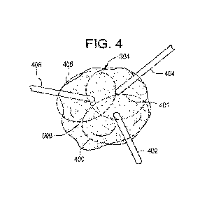
Figure 4 illustrates the use of multiple ablation probes; namely, ablation
probe one 402, ablation probe two 404, and ablation probe three 406 for the
ablation of the tumor 304 based on the volumetric burn region, ablation region
one
401, ablation region two 403, and ablation region three 405 of each of the
ablation
probes inserted into the tumor 304. It is important to note that three probes
were
chosen here for exemplary purposes. Typically, the probes would be introduced
in
a somewhat parallel fashion and not from completely different directions as
CA 03162550 2022-05-20
WO 2021/105785 PCT/IB2020/059518
19
illustrated for ease of explanation. A number of factors described herein
determine
the number of probes to be utilized as well as their trajectories. With the
variation
in the target's volumetric size and location within the body, multiple probes
as
shown in this figure would be utilized to provide the target with the needed
ablation
to cover the regions of the tumor. As an illustrative example, this may be
completed by the system being capable of calculating the region of burn for
each
ablation probe depending on its location within the tumor relative to
intensity of the
energy delivery, size of the ablation probe, nearby heat sinks, and other
general
factors.
Figure 5 illustrates the aforementioned heat sink effects for the ablation
probe when in the tumor 304. For exemplary reasons, a single, simple ablation
probe 501 is illustrated in the image. It is important to note that any
suitable type of
probe may be utilized whereas an ablation probe is one such example. As shown
in the figure, the ablation energy delivery region or distal tip 503 of the
ablation
probe 501 is within some region of the tumor 304. There is a nearby major
blood
vessel 505 that provides a heat sink effect for that region of tissue and thus
should
be avoided. As a non-limiting example, the system within the disclosure
described
herein may utilize an algorithm to predict the modified burn regions with
respect to
heat sink regions 507 and non-heat sink regions 509. As such, the system is
able
to predict/calculate the regions of burn 511 with respect to specific ablation
probes
used.
Figure 6A illustrates a single calculated trajectory to the site of ablation
in
the tumor (e.g., based on the computational geometry algorithm). Although
reference is made to ablation of a tumor other probes and procedures may
benefit
from the systems and methods described herein. In the figure, the determined
(e.g., calculated) trajectory 615 to the center 614 of the tumor 304 along the
predetermined path is seen beginning at the surface of the virtual patient 600
and
ending in the ablation site within the tumor 304.The system itself is designed
to
allow for the real-time monitoring of the calculated path or trajectory 615
with an
CA 03162550 2022-05-20
WO 2021/105785 PCT/IB2020/059518
ultrasound 619 device illustrated in Figures 6B and 60. Figures 6B and 60
illustrate the method of visualization for the calculated path or trajectory
615
relative to different ultrasound orientations; namely, perpendicular to the
calculated
path or trajectory 615 or along the calculated path or trajectory 615. In
Figure 6B,
5 the ultrasound device 619 is oriented perpendicular to the calculated
path or
trajectory 615, creating an ultrasound slice 620 at some depth of the
calculated
path or trajectory 615. The resulting ultrasound image 621 has the overlaid
calculated path or trajectory 615 shown as the perpendicular cross-section of
a
customizable shape, object, or image 622. In Figure 60, the ultrasound device
619
10 is oriented along the directional axis of the calculated path 615,
creating an
ultrasound slice 620 along a larger portion of the calculated path or
trajectory 615,
if not all of it. The resulting image 621 has the overlaid calculated path
trajectory
615 shown as an in-line axial cross-section of the customizable shape, object,
or
image 623. In addition to the calculated path or trajectory 615 overlaid on
the
15 ultrasound image 621, the projected trajectory as well as the actual
location of the
ablation probe in real-time are also tracked on the image.
Figure 7 illustrates point 717 as an example entry point for a probe 716. A
calculated trajectory projection 718 may be determined based on the real-time
20 location of the ablation probe 716 at the time of the procedure or
during planning
studies. The calculated trajectory projection 718 may be projected line
calculated
based on the angulation and location of the real-time ablation probe 716. As
shown, the calculated trajectory projection 718 may be overlaid on an image
such
as an ultrasound image (e.g., image 621 in Figures 6B and 60) to allow a user
to
visualize a projection of the calculated trajectory of the probe 716. In this
example,
the calculated trajectory projection 718 is shown missing the ablation site
714
which is the center of the tumor 304. Thus, a user may determine that based on
the calculated trajectory projection 718, correction is necessary. As a
further
example, a planned trajectory 715 may be calculated and overlaid on the image
to
allow a user to compare the planned trajectory 715 with the calculated
trajectory
projection 718 and to make adjustments based on the same. As an illustrative
CA 03162550 2022-05-20
WO 2021/105785 PCT/IB2020/059518
21
example, a user may align the calculated trajectory projection 718 with the
planned trajectory 715 in order to follow the planned path to a particular
location
(e.g., the ablation site 714). In addition to the projection 718, the
projection or
trajectory item (or other elements in display) may changes colors or some
significant element of its item when the ultrasound is creating a sliced image
over
the actual ablation probe 716. This additional indicator may aid the user in
knowing the real-time location of the ablation probe 716 during any planning
or
insertion steps. All of the calculated trajectories, both pre-planned and real-
time
trajectories, all may be displayed on the a display device such as a screen or
a
visualization headset in addition to being represented in the overlaid
ultrasound
image.
At the stage of ablation probe insertion, the following figures are used to
describe a potential series of steps that can be taken to get the ablation
probe to
the calculated zone/point. It is important to note that this is not the only
series of
steps that can be taken for this portion of the procedure.
Figure 8A illustrates the introduction sheath system inclusive of its
introduction sheath handle 802, receiver 804, introduction sheath locking
mechanism 806, and the introduction sheath 808 itself. This system can be used
as the initial insertion, where the introduction stylet 810 is used in place
of the
ablation probe 716 all the way to the site of ablation at the tumor 304 along
the
pre-determined surgical path 815. Its position is tracked and utilized for all
of the
imaging and calculations with the use of the receiver 804. Once the
introduction
stylet 810 reaches the calculated depth and location, the introduction sheath
locking mechanism 806 is engaged to lock that location in space relative to
the
patient and its respective body. Figure 8B moves onto the next stage of the
ablation probe 716 insertion process, by removing the introduction stylet 810
from
the overall assembly. This opens up the connection point 802 that has the
ability to
mate with multiple parts, in this figure, the introduction sheath 808 is shown
resting
before the tumor 304, due to the introduction stylet 810 and the ablation
probe 716
CA 03162550 2022-05-20
WO 2021/105785 PCT/IB2020/059518
22
having the same geometries resulting in the same end offset location in the
tumor
304. Again, that location being the calculated one from the software. Figure
80
now brings in the actual ablation probe 716 insertion into the already set
path and
location created by the introduction stylet 810. As shown with the tip 807 of
the
ablation probe 716, it is exactly at the same terminal point that the
introduction
stylet 810 was at, and where the calculated site of ablation is based on the
software. As a non-limiting example, software of the present disclosure may
determine the optimal placement and energy emitted by each probe to ensure no
interference between probes. A more detailed description of the ablation probe
may be found in US Patent Publication 2018/0132934. It is important to note;
however, that any suitable ablation probe may be utilized in accordance with
the
present disclosure.
Figure 9 illustrates the acoustic feedback or similar/non-similar mechanism
used for proximity to tumor feedback. For the acoustic example, as the
introduction stylet 810, ablation probe 716, or similar item approaches the
tumor
304 (Figures 8A, 8B and 80) the user is presented with a specified sound and
pitch or increasing occurrence or modification of said items. This will ensure
the
user is aware of the location of the introduction stylet 810, ablation probe
716, or
similar item with respect to the target in addition to just the visual cues.
Referring now to Figure 10, Illustrated here is a more detailed
representation of the exemplary ablation probe assembly 500. The exemplary
probe 500 comprises a cooling tube 502 and cable assembly 504 connected to a
probe handle assembly 506. The probe handle 506 is connected to an antenna
portion 508 via a cooled probe cannula 510. The region between the cooled
probe
cannula 510 and the antenna portion 508 comprises a stick portion 512 and a
plug
portion 514. The stick portion 512 is designed to attain and maintain a
temperature
accommodating adherence of a tissue region onto its surface. The plug portion
514 is designed to prevent a reduction in temperature resulting from the
cooled
probe cannula 510 and the stick portion 512 from affecting the temperature
within
CA 03162550 2022-05-20
WO 2021/105785 PCT/IB2020/059518
23
the antenna portion 508. The ablation zone 516 is the energy pattern emitted
by
the antenna portion 508 for this single probe. As a non-limiting example,
software
of the present disclosure may determine the optimal placement and energy
emitted by each probe to ensure no interference between probes.
With reference made to Figures 11A-11F, a method for determining a
preferred pathway from a three-dimensional image of a region of the body is
disclosed. As an example a method may comprise visualizing a three dimensional
image of a region of the body with respect to a known reference frame, as
shown
in Figures 11A-11F. A method may comprise rotating the three dimensional image
in the space in two dimensional spaces and obtaining vector information of a
viewing plane, as shown in Figures 11A-11f. Methods may comprise determining a
select body orientation to provide line-of-sight of a target location,
obtaining spatial
information of the target location with respect to the viewing plane, and/or
determining a line in space based on at least the viewing plane and the
spatial
information of the target location defined with respect to the viewing plane.
The
line in space may represent at least a portion of the preferred pathway.
Methods
may further comprise determining a fiducial point that is associated with the
line in
space. The fiducial point may be determined based on automated feature
recognition. The fiducial point may be an end point of the preferred pathway.
The
fiducial point may be an entry point on the external surface of the portion of
the
body being treated. As an example, the fiducial point may be determined using
one or more of the following steps: visualizing a plane perpendicular to the
initial
viewing plane having the line in space represent the x-axis; and selecting on
the
line in space, an end point, while visualizing an imaging plane containing the
line
in space. Methods of determining the fiducial point may comprise selecting on
the
line in space, an entry point on the external surface of the body being
treated,
while visualizing an imaging plane containing the line in space. Other methods
may be used.
CA 03162550 2022-05-20
WO 2021/105785 PCT/IB2020/059518
24
A method for navigating a probe to a location within a body of a patient, the
method comprising the steps of: visualizing a three-dimensional image of a
region
of a body of a patient; receiving a selection of a target location within said
three-
dimensional image of a region of a patient's body; determining and visualizing
a
preferred pathway for the probe to follow from an external entry point on the
patient's body to the target location; registering the three-dimensional image
to the
current actual position of the corresponding region of the patient's body;
registering the current actual position of the probe to the three-dimensional
image
and the current actual position of the patient's body; visualizing the
preferred
pathway for the probe simultaneously with an indication of the current actual
position of the probe in real time such that the simultaneous visualizations
enables
a user to align the current actual position of the probe with the preferred
pathway;
and updating and visualizing an indication of the current actual position of
the
probe in real time as the probe is advanced to the target location.
The present disclosure relates to a method and associated system for
guided navigation of one or more probes to locations within a body of a
patient.
The present disclosure is also directed to a method of and associated system
for
determining an accurate three-dimensional model of a tumor and its surrounding
environment, inclusive of anatomical structure, as well as a means for
automatically calculating the number of energy radiating probes and their
respective positioning/trajectory specifics within the tumor(s) to ensure no
destructive interference of the radiating energy in the patient and the
complete
eradication of the targeted cancerous cells. To achieve optimal trajectories
for
each probe utilized to ensure complete tumor destruction, the methodology of
the
present disclosure includes predictive analytics which account for the effects
of
tissue shrinkage due to electro-magnetic radiation exposure. In addition, the
methodology of the present disclosure includes a means for accounting for
anatomical shifting between initial scans and procedures as well as accounting
for
any phase-cancellation effects of using multiple microwave ablation probes.
CA 03162550 2022-05-20
WO 2021/105785 PCT/IB2020/059518
The present disclosure also relates to a method for the three-dimensional
modeling of tumors and the ablation thereof, and more particularly to a method
and associated system for the three-dimensional modeling of tumors and
surrounding tissue, the analysis of the models and the precise and complete
5 ablation of the tumors based upon information from the models and
analysis,
including tumor geometry, electro-magnetic wave phase interference, heat
sinking anatomical features and critical anatomy, to determine the number of
ablation probes to utilize, the energy radiated by each probe, as well as the
optimal trajectories for each probe. To achieve optimal trajectories for each
probe
10 utilized to ensure complete tumor destruction, the methodology of the
present
disclosure includes predictive analytics which account for the effects of
tissue
shrinkage due to electro-magnetic radiation exposure, for example, microwave
radiation.
The present disclosure provides a means for mapping the electro-magnetic
radiation distribution around the energy radiating probe, accounting for any
heat
sinking effects caused by near anatomical structures, providing predictive
insights
for positioning/tracking of any and all necessary energy radiating probes.
The present disclosure provides a means for the efficient and effective
eradication of tumors as well as other undesirable tissue. The present
disclosure
may be utilized in conjunction with existing technology to provide truly
accurate
irradiation treatment.
The present disclosure may be utilized in conjunction with any type of
probe. For example, the probe may be configured to emit RF energy, microwave
energy, ultrasound energy, light energy and an electric field capable of
causing
irreversible electroporation. Non-energy emitting probes may also be utilized
in
accordance with the present disclosure.
CA 03162550 2022-05-20
WO 2021/105785 PCT/IB2020/059518
26
The present disclosure comprises methods of determining an accurate
three-dimensional model of the tumor and its surrounding environment, as well
as
a means for automatically calculating the number of and positioning/trajectory
of
the energy radiating probes within the tumor(s) to ensure no destructive
interference of the radiating energy and the complete eradication of the
cancerous
cells. In addition, any method should preferably include predictive analytics
which
account for the effects of tissue shrinkage due to electro-magnetic radiation
exposure, for example, microwave radiation. In addition, the method may
preferably include automatically guiding and positioning of the probes as well
as a
means for accounting for anatomical shifting.
Although shown and described in what is believed to be the most practical
and preferred embodiments, it is apparent that departures from specific
designs
and methods described and shown will suggest themselves to those skilled in
the
art and may be used without departing from the spirit and scope of the
disclosure.
The present disclosure is not restricted to the particular constructions
described
and illustrated but should be constructed to cohere with all modifications
that may
fall within the scope of the appended claims.