Note : Les revendications sont présentées dans la langue officielle dans laquelle elles ont été soumises.
1
CLAIMS:
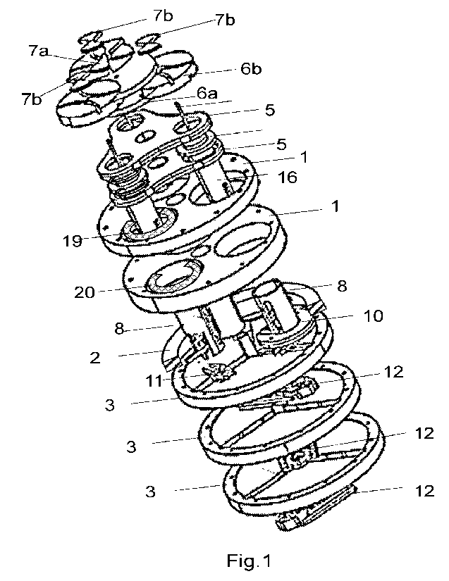
1. An infinitely variable transmission comprising:
one or more driving Geneva pin wheels mounted on an input shaft, operably
connected to one or more
driven Geneva slot wheels each operably connected to rotate an input disk of a
scotch yoke mechanism,
causing a crank pin of the scotch yoke mechanism, placed at an offset distance
to an axis of rotation of the
input disk where the offset distance can be altered from 0 to a real value
using an external force, to revolve
around the axis of rotation of the input disk, which reciprocates one or more
racks, which are restricted to only
move along the rack's pitch line and each rack rocks a pinion comprising a one
way bearing that is mounted
on a hollow output shaft that is co-axially placed with the input shaft,
wherein the input shaft passes
completely through the output shaft.
2. An infinitely variable transmission comprising:
A) at least one scotch yoke module comprising:
a. a crank pin revolving around
b. a notched input shaft, at an offset distance between a longitudinal
axes of the crank pin and
the auxiliary input shaft that remain parallel to each other, and the offset
distance that can
be altered when the crank pin is co-axial to the auxiliary input shaft from
zero to a non-zero
real number by displacing the crank pin along a radial slot of
c. an input disk rigidly mounted on the input shaft, by
B) a crank pin displacement mechanism comprising:
a. a sliding collar disposed co-axially with the auxiliary input shaft with a
feature preventing
relative angular displacement while allowing relative translation,
b. a link assembly comprising
i. a link pivoting the crank pin through the notch
ii. a crank pin pivot pin on one end and pivoting the sliding collar about
iii. a sliding collar pivot pin on another end of the link,
c. at least one thrust bearing that is co-axially placed in contact with the
sliding collar, such that
an external force applied on the thrust bearing causing an axial displacement
of the thrust
bearing along with the sliding collar with respect to the auxiliary input
shaft, alters the offset
distance by moving the crank pin along the radial slot of the input disk,
d. a slotted rack holder comprising one or more racks, which is restricted to
only move along a
direction of the longitudinal axis of the one or more racks, and a crank pin
slot for receiving
the crank pin, with a longitudinal axis of the crank pin slot orthogonal to
the one or more
racks,
C) at least one angular velocity module comprising:
2
a. an input shaft,
b. one or more driving Geneva pin wheels mounted on the input shaft and
driving
c. at least one driven Geneva slot wheel each rotating the input shaft
D) at least one rectifier module comprising:
a. a pinion engaged with the rack, and mounted on
b. a pinion shaft through
c. a computer-controlled clutch, a one-way clutch or a ratchet mechanism
arranged such that a uniform rotation of the driving Geneva pin wheel via the
input shaft, causes a non-
uniform angular velocity of the input shaft via the driven Geneva slot wheel
and the planetary gear system,
causing the crank pin to reciprocate the rack substantially along a
longitudinal direction of the rack at a
substantially constant velocity and slowing down briefly during direction
reversal and accelerating to the
constant velocity, where a magnitude of the reciprocation is proportional to
the offset distance of the crank pin
and the auxiliary input shaft, and this reciprocation of the rack causes an
alternating rotation of the pinion and
this alternating rotation of the pinion is converted to a unidirectional
rotation of the pinion shaft via the
computer-controlled clutch, the one-way clutch or the ratchet mechanism.
3. The infinitely variable transmission of claim 2, wherein the feature
preventing relative angular displacement
while allowing relative translation between the sliding collar and the
auxiliary input shaft is further defined as
one of the co-axially placed sliding collar or the auxiliary input shaft
having a non-circular cross section and
the other of the sliding collar and the auxiliary input shaft having a non-
circular orifice matching the non-
circular cross section.
4. Currently Amended) A infinitely variable transmission comprising:
A) at least one scotch yoke module comprising:
a)a crank pin perpendicularly mounted on
b)a crank pin collar having a non-circular orifice and sliding on
c)a co-axial crank pin collar shaft having a matching non-circular cross-
section, and the crank
pin collar shaft is mounted perpendicularly on
d) a notched auxiliary input shaft, such that a longitudinal axis of the crank
pin is coplanar and
parallel and at an offset distance to the longitudinal axes of the auxiliary
input shaft,
wherein the offset distance can be altered by displacing the crank pin by
e) a crank pin displacement mechanism comprising:
i. a sliding collar disposed co-axially with the auxiliary
input shaft, wherein one of the
sliding collar and the auxiliary input shaft has a non-circular cross-section
and another
of the sliding collar and the auxiliary input shaft has a matching non-
circular orifice,
3
such that the sliding collar and the auxiliary input shaft rotate
synchronously with each
other while having the ability to slide axially relative to each other,
ii. a link assembly comprising
a) a link pivoting on the sliding collar and the crank pin collar through
the notch
b) a sliding collar pivot pin on one end of the link and pivoting the crank
pin collar
with
c) a crank pin collar pivot pin on another end
f) at least one thrust bearing that is co-axially placed in contact with
the sliding collar, such
that an external force applied on the thrust bearing causes an axial
displacement of the
thrust bearing and the sliding collar with respect to the auxiliary input
shaft, which alters
the offset distance by moving the crank pin collar together with the crank pin
along the
crank pin collar shaft,
g) a slotted rack holder comprising one or more racks, which is restricted to
only move
along a direction of a longitudinal axis of the one or more racks, and a crank
pin slot for
receiving the crank pin, with a longitudinal axis of the crank pin slot
orthogonal to the one
or more racks,
B) at least one angular velocity module comprising:
a) an input shaft,
b) at least one driving Geneva pin wheel mounted on the input shaft and
driving
c) at least one driven Geneva slot wheel mounted co-axially on the
auxiliary input shaft, at a
fixed orientation to the axis of the crank pin shaft and
C) at least one rectifier module comprising:
a) a pinion engaged with the one or more racks, and mounted on
b) a pinion shaft through
c) a computer-controlled clutch, a one-way bearing, or a ratchet mechanism;
arranged such that a uniform rotation of the driving Geneva pin wheel via the
input shaft, causes a non--
uniform angular velocity of the auxiliary input shaft via the driven Geneva
slot wheel, causing the crank pin to
revolve the auxiliary input shaft reciprocating the one or more racks
substantially along a longitudinal direction
of the one or more racks at a substantially constant velocity and slowing down
briefly during direction reversal
and accelerating to the constant velocity, where a magnitude of the
reciprocation is propodional to the offset
distance of the crank pin and the auxiliary input shaft, and this
reciprocation of the rack causes an alternating
rotation of the pinion and the rotation of the pinion is converted to a
unidirectional rotation of an output gear,
or output sprocket mounted on the pinion shaft via the computer controlled
clutch, the one way bearing or the
ratchet mechanism.
4
5. The infinitely variable transmission of claim 2, wherein rotation ratio of
driving Geneva pin wheel of the
driven Geneva slot wheel, when expressed using Cartesian coordinates (X1, Y1)
and (X2, Y2) respectively, as
a function of angle 19 are
where 4,(9) is a solution to a piece-wise differential equation
<IMG>
function of any linear or nonlinear curve connecting points
<IMG>
<IMG>
ki if 0,i < < 02i,
function of any linear or nonlinear curve connecting points (02i3O)to
(03i,¨ki)
if 02i < 0 < 03.
¨ki if 03. < 0 < 04i,
function of any linear or nonlinear curve connecting points (94i, 0) to
<IMG>
or
<IMG>
function of any linear or nonlinear curve connecting points (0,i,ki)to (92,
¨ki)
if 01i < <192i,
¨ki if 02i < O < 03i,
function of any linear or nonlinear curve connecting points (03i,¨ki) to
(04i,ki)
<IMG>
where boundary conditions are
<IMG>
where
CTR is a center to center distance of the driving Geneva pin wheel and the
driven Geneva slot wheel,
0 is an angular displacement of the driving Geneva pinwheel;
(1) is an angular displacement of the driven Geneva slot wheel;
i refers to an i-th revolution the input disk from 0 to N*n-1 with a 1st
rotation being i=0;
N is a number of times the input disk rotates when the driven Geneva pin wheel
rotates once;
n is a number of times the driven Geneva slot wheel rotates when the driving
Geneva slot wheel once;
regions where the piece-wise function for the rack velocity is constant are
functional regions and regions
where the piece-wise function for the rack velocity is not constant are non-
functional regions which can be
linear or non-linear functions of 0;
191i,192i, 193i, 194i are specific angular positions of the driving Geneva pin
wheel, the values of which are
solved for using a solution to the piece-wise differential equation;
(1,2, (1,3, (1,4 are specific angular positions of the driven Geneva slot
wheel corresponding to angular
positions 191i,192i093i094i of the driving Geneva pin wheel respectively, and
are a cutoff between the
functional and non-functional regions, values of ci) , 2 , OP 3 , cP 4 which
can to be solved for by using arbitrary
values for 01,,
and ki are constants, which are all equal.
8 The infinitely variable transmission of claim 2, further comprising one or
more additional driving Geneva pin
wheel and driven Geneva slot wheel pairs, wherein the pairs of driving Geneva
pin wheel and driven
Geneva slot wheel are stacked in layers and a sum ot all functional regions of
all the pairs of driving
Geneva pin wheel and driven Geneva slot wheel in each angular velocity module
is greater than or equal
to 360- and is placed such that the Geneva pin wheel and slot wheel pairs are
in the functional region in
sequence with an overlap between the functional regions of consecutive driven
Geneva slot wheels.
CA 03165829 2022- 7- 22
PCT/US2021/017984
6
7) The infinitely variable transmission of claim 2, wherein the
angular velocity modules are oriented such
that their Geneva pin wheel and the Geneva slot wheel are in the functional
region in sequence with an
overlap when the input disk completes approximately one rotation, ensuring
that at least one angular
velocity module is in the functional region at any given time.
8) The infinitely variable transmission of claim 18, wherein an amount of
overlap between each pair of
consecutively engaged rectifier modules are substantially identical.
9) The infinitely variable transmission of claim 2, further comprising a dead
weight and a wheel that transfers
motion from the rack to a dummy rack with teeth identical to the rack and
located 180 degrees relative to
the rack, and the dummy rack moves in a substantially opposite direction of
the rack.
10) The infinitely variable transmission of claim 2, further comprising a
dummy crank pin having a mass
substantially identical to a mass of the crank pin that slides in an opposite
direction of the crank pin.
11) The infinitely variable transmission of claim 2, further comprising:
a differential assembly comprising an input miter bevel gear and a pair of
substantially co-axial output
miter bevel gears operably connected with the input miter bevel gear such that
the output miter bevel
gears rotate in opposite directions, each output miter bevel gear having a
through-bore substantially at a
central axis thereof and substantially co-axial with each other;
a through-shaft positioned through the through-bores of the output miter bevel
gears; and a pair of collars
operably coupled with the through-shaft and rotatably fixed therewith, each
collar configured to move
axially along the through-shaft independently of the other collar and
configured to engage with one of the
output miter bevel gears;
wherein the power link shaft is operably coupled with the input miter bevel
gear to cause rotation of the
input miter gear.
12) The infinitely variable transmission of claim 11, wherein:
when a first one of the collars is engaged with a first one of the output
miter bevel gears and a second
one of the collars is not engaged with a second one of the output miter bevel
gears, the through-shaft
rotates about its longitudinal axis in a first direction corresponding to a
rotational direction of the first one
of the output miter bevel gears; and
when the second one of the collars is engaged with the second one of the
output miter bevel gears and
the first one of the collars is not engaged with the first one of the output
miter bevel gears, the through-
shaft rotates about its longitudinal axis in a second direction corresponding
to a rotational direction of the
second one of the output miter bevel gears.
13) The infinitely variable transmission of claim 11, wherein when neither of
the collars is engaged with the
output miter bevel gears, the through-shaft is free to rotate in any direction
about its longitudinal axis.
CA 03165829 2022- 7- 22
PCT/US2021/017984
7
14) The infinitely variable transmission of claim 11, wherein when each of the
collars is engaged with a
respective one of the output miter bevel gears, the through-shaft is
restricted from rotating about its
longitudinal axis.
15) The infinitely variable transmission of claim 14, wherein the input shaft
is connected to a ring gear, a
carrier or a sun gear, the output from the output gear thru an output shaft is
connected to another one of
the ring gear, the carrier or the sun gear and the final output is connected
to another one of the ring
gear, the carrier or the sun gear.
16) The infinitely variable transmission of claim 14, wherein a final output
from a planetary gear system
temporarily stores energy in a fly-wheel-system and later delivers power back
to the input shaft or to a
wheel-system.
17) A infinitely variable transmission comprising:
A) at least one scotch yoke module comprising:
h)a crank pin perpendicularly mounted on
i) a crank pin collar having a non-circular orifice and sliding on
j) a co-axial crank pin collar shaft having a matching non-circular cross-
section, and the crank
pin collar shaft is mounted perpendicularly on
k) a notched auxiliary input shaft, such that a longitudinal axis of the crank
pin is coplanar and
parallel and at an offset distance to the longitudinal axes of the auxiliary
input shaft,
wherein the offset distance can be altered by displacing the crank pin by
0 a crank pin displacement mechanism comprising:
iii. a sliding collar disposed co-axially with the auxiliary input shaft,
wherein one of the
sliding collar and the auxiliary input shaft has a non-circular cross-section
and another
of the sliding collar and the auxiliary input shaft has a matching non-
circular orifice,
such that the sliding collar and the auxiliary input shalt rotate
synchronously with each
other while having the ability to slide axially relative to each other,
iv. a link assembly comprising
d) a link pivoting on the sliding collar and the crank pin collar through
the notch
e) a sliding collar pivot pin on one end of the link and pivoting the crank
pin collar
with
0 a crank pin collar pivot pin on another end
m) at least one thrust bearing that is co-axially placed in contact with the
sliding collar, such
that an external force applied en the thrust bearing causes an axial
displacement of the
thrust bearing and the sliding collar with respect to the auxiliary input
shaft, which alters
the offset distance by moving the crank pin collar together with the crank pin
along the
crank pin collar shaft,
CA 03165829 2022- 7- 22
PCT/US2021/017984
8
n) a slotted rack holder comprising one or more racks, which is restricted to
only move
along a direction of a longitudinal axis of the one or more racks, and a crank
pin slot for
receiving the crank pin, with a longitudinal axis of the crank pin slot
orthogonal to the one
or more racks,
B) at least one angular velocity module comprising:
d) an input shaft,
e) at least one driving Geneva pin wheel mounted on the input shaft and
driving
f) at least one driven Geneva slot wheel mounted co-axially on the
auxiliary input shaft, at a
fixed orientation to the axis of the crank pin shaft and
C) at least one rectifier module comprising:
a) a pinion engaged with the one or more racks, and mounted on
b) a pinion shaft through
c) a computer-controlled clutch, a one-way bearing, or a ratchet mechanism;
arranged such that a uniform rotation of the driving Geneva pin wheel via the
input shaft, causes a non-
uniform angular velocity of the auxiliary input shaft via the driven Geneva
slot wheel, causing the crank pin to
revolve the auxiliary input shaft reciprocating the one or more racks
substantially along a longitudinal direction
of the one or more racks at a substantially constant velocity and slowing down
briefly during direction reversal
and accelerating to the constant velocity, where a rnagnitude of the
rec.iprocation is proportional to the offset
distance of the crank pin and the auxiliary input shaft, and this
reciprocation of the rack causes an altemating
rotation of the pinion and the rotation of the pinion is converted to a
unidirectional rotation of an output gear,
or output sprocket mounted on the pinion shaft via the computer controlled
clutch, the one way bearing or the
ratchet mechanism.
18. An infinitely variable transrnission comprising:
A) at least one scotch yoke module comprising:
a. a crank pin revolving around
b, a notched auxiliary input shaft, at an offset
distance between longitudinal axes of the
crank pin and the auxiliary input shaft that remain parallel to each other,
and the offset
distance that can be altered from zero when the crank pin is co-axiai to the
auxiliary input
shaft to a non-zero real n u m be r by displacing the crank pin along a radial
siot of
c. an input disk rigidly mounted on the auxiliary input
shaft, by
B) a crank pin displacement mechanism cornprising:
a. a sliding collar disposed co-axially with the
auxiliary input shaft with a feature
preventing relative angular displacement while allowing relative translation,
CA 03165829 2022- 7- 22
PCT/US2021/017984
9
b. a link assembly comprising
i. a link pivoting the crank pin through the notch
ii. a crank pin pivot pin on one end and pivoting the sliding collar about
iii. a sliding collar pivot pin on another end of the link,
c. at least one thrust bearing that is co-axially placed
in contact with the sliding collar,
such that an external force applied on the thrust bearing causing an axial
displacement of
the thrust bearing along with the sliding collar wfth respect to the auxiliary
input shaft, afters
the offset distance by moving the crank pin along the radial slot of the input
disk,
d. a slotted rack holder comprising one or more racks,
which is restricted to only move
along a direction of the longitudinal axis of the one or more racks, and a
crank pin slot for
receiving the crank pin, with a longitudinal axis of the crank pin slot
orthogonal to the one or
more racks,
C) at least one angular velocity module comprising:
a. an input shaft,
b. one or more driving circular or non-circular gear mounted on the input
shaft and
driving
c. at least one driven circular or non-circular gear that is mounted free
(o spin on a
fixed shaft, where the driven non-circular gear further functions as a carrier
of a planetary
gear system, with
d. at least one free to spin planet gear meshing with a stationary sun gear
mounted
on the fixed shaft and is axially attached to
e. a primary cam that is operably engages with
f. a secondary cam that is mounted on the auxiliary input shaft and
0) at least one rectifier module comprising:
a. a pinion engaged with the rack, and mounted on
b. a pinion shaft through
c. a computer-controlled clutch, a one-way clutch or a ratchet mechanism
arranged such that a uniform rotation of the driving non-circular gear via the
input shaft, causes a non-uniform
angular velocity of the auxiliary input shaft via the driven non-circular gear
and the planetary gear system,
causing the crank pin to reciprocate the rack substantially along a
longitudinal direction of the rack at a
substantially constant velocity and slowing down briefly during direction
reversal and accelerating to the
constant velocity, where a magnitude of the reciprocation is proportional to
the offset distance of the crank pin
CA 03165829 2022-7-22
PCT/US2021/017984
and the auxiliary input shaft, and this reciprocation of the rack causes an
alternating rotation of the pinion and
this alternating rotation of the pinion is converted to a unidirectional
rotation of the pinion shaft via the
computer-controlled clutch, the one-way clutch or the ratchet mechanism.
19. An infinitely variable transmission comprising:
A) at least one scotch yoke module comprising:
a. a crank pin revolving around
b. a notched auxiliary input shaft, at an offset distance between
longitudinal axes of the
crank pin and the auxiliary input shaft that remain parallel to each other,
and the offset
distance that can be altered from zero when the crank pin is co-axial to the
auxiliary input
shaft to a non-zero real number by displacing the crank pin along a radial
slot of
c. an input disk rigidly mounted on the auxiliary input shaft, by
B) a crank pin displacement mechanism comprising:
a. a sliding collar disposed co-axially with the
auxiliary input shaft with a feature
preventing relative angular displacement while allowing relative translation ,
b. a link assembly comprising
i. a link pivoting the crank pin through the notch
ii. a crank pin pivot pin on one end and pivoting the sliding collar about
iii. a sliding collar pivot pin on another end of the link,
c. at least one thrust bearing that is co-axially placed
in contact with the sliding collar,
such that an external force applied on the thrust bearing causing an axial
displacement of
the thrust bearing along with the sliding collar with respect to the auxiliary
input shaft, alters
the offset distance by moving the crank pin along the radial slot of the input
disk,
d. a slotted rack holder comprising one or more racks,
which is restricted to only move
along a direction of the longitudinal axis of the one or more racks, and a
crank pin slot for
receiving the crank pin, with a longitudinal axis of the crank pin slot
orthogonal to the one or
more racks,
C) at least one angular velocity rnodule cornprising:
a, an input shaft,
b. one or more driving circular or non-circular gear mounted on the input
shaft and
driving
c. at least one driven circular or non-circular gear that is mounted free
to spin on a
fixed shaft, where the driven non-circular gear further functions as a carrier
of a planetary
gear system, with
CA 03165829 2022-7-22
PCT/US2021/017984
11
d. at least one free to spin planet gear meshing with a stationary ring
gear that is
mounted on a frame and is axially attached to
e. a primary cam that is operably engages with
f. a secondary cam that is mounted on the auxiliary input shaft and
D) at least one rectifier module comprising:
a. a pinion engaged with the rack, and mounted on
b. a pinion shaft through
c. a computer-controlled clutch, a one-way clutch or a ratchet mechanism
arranged such that a uniform rotation of the driving non-circular gear via the
input shaft, causes a non-uniform
angular velocity of the auxiliary input shaft via the driven non-circular gear
and the planetary gear system,
causing the crank pin to reciprocate the rack substantially along a
longitudinal direction of the rack at a
substantially constant velocity and slowing clown briefly during direction
reversal and accelerating to the
constant velocity, where a magnitude of the reciprocation is proportional to
the offset distance of the crank pin
and the auxiliary input shaft, and this reciprocation of the rack causes an
alternating rotation of the pinion and
this alternating rotation of the pinion is converted to a unidirectional
rotation of the pinion shaft via the
computer-controlled clutch, the one-way clutch or the ratchet mechanisrn.
CA 03165829 2022-7-22