Note : Les descriptions sont présentées dans la langue officielle dans laquelle elles ont été soumises.
WELL CASING/TUBING DISPOSAL
Field of the Invention
The present invention relates in general to P&A (plugging and abandonment) and
work-over operations for underground conduits such as oil/gas wells, and in
particular to the removal or disposal of oil well elements such as well
casing/tubing.
Background of the Invention
Once an oil/gas well has come to the end of its useful life, the well needs to
be safely
decommissioned. An important aspect of decommissioning is the plugging and
abandonment (P&A) of the well. The plugging of an abandoned well is necessary
to
seal it off and prevent the escape of hydrocarbons and gases from within the
well.
Various methods are known in the art for providing both permanent and
removable
plugs within abandoned wells. In some situations a plug may be deployed within
a
well casing that is itself deployed within a bore hole within the ground.
In other situations it is desirable to deploy a plug which extends across the
whole
cross-section of a bore hole. In these situations it is first necessary to
remove the
well casing from the region of the bore hole where the plug is to be deployed.
It is known in the art to remove a well casing from within a well bore hole by
mechanical means, such as milling or drilling. Such mechanical approaches can
be
time consuming and, as a result, expensive. They also produce debris in the
form of
swarf as the casing is broken down, which can interfere with both the milling
/drilling
itself and any subsequent plugging operation.
In addition, any swan f produced is classed as contaminated material that
needs to be
disposed of in accordance with strict regulations. This disposal can be very
expensive in wells that are located away from the mainland out at sea.
Other suggested approaches involve the use of heat generating mixtures, such
as
thermite, to melt not only the well casing but also the surrounding materials
of the
-1-
Date Recue/Date Received 2022-07-07
well (e.g. concrete, formation sand). The aim of melting the well casing (and
surrounding materials) is to make use of the materials within the well to
actually form
a plug rather than removing or disposing of the casing.
However, due to the mixture of materials that are melted to form the plug, the
effectiveness (e.g. gas tight sealing and resistance to chemical erosion) of
these
plugs is more difficult to predict than plugs formed from more homogenous
compositions (i.e. eutectic alloys or cement).
On other occasions, rather than carrying out plugging and abandonment (P&A)
operations on a well, the aim is to carry out work-over operations so as to
repair an
underground conduit that has become damaged or blocked for whatever reason.
The above mentioned mechanical and heat based approaches are also employed
during such operations to clear obstacles from within the well to facilitate
subsequent
repair work to be carried out.
Summary of the Invention
The present invention provides methods for use in the removal of well casing
and
tubing from underground conduits, such as oil/gas wells, to facilitate the
subsequent
deployment of abandonment plugs within said conduit.
The term 'removal' is used in its broadest sense throughout, in so far as it
is the
object of the various aspects of the method of the present invention to clear
well
casing/tubing from a targeted region of well bore hole so as to either expose
the
surrounding rock formation within which the borehole of the oil/gas well is
formed or
remove tubing (e.g. production tubing) from within a well casing to clear a
path for
the deployment of repair tools.
In the case of clearing casing/tubing to expose the surrounding rock formation
the
clearance formed facilitates the plugging of the entire cross-section of the
well bore
hole, which allows the formation of a better seal.
In the case of clearing tubing (e.g. such as production tubing) from within a
well
casing the clearance formed facilitates subsequent repair work to be carried
out by
removing obstacles to the deployment of the repair tools.
-2-
Date Regue/Date Received 2022-07-07
Whether the objective is to form a seal that extends across the entire cross-
section
of a well bore (i.e. from rock formation to rock formation) or to remove
existing tubing
from within a well casing to clear a path for the deployment of repair tools,
it is
envisioned that the methods described hereinafter provide effective solutions.
It is considered important that the various aspects of the method work on the
physical properties of the well casing/tubing in such a way that the build-up
of debris
(e.g. swan) in the target region. In this way the method of the invention acts
to
provide a clear work space for the subsequent formation of an effective well
abandonment plug, be such a eutectic alloy plug, an ordinary cement plug, or
any
other known plugging technology.
According to a first aspect of the present invention there is provided a
method of
clearing well casing or tubing from a target region of an oil/gas well
borehole, said
method comprising: delivering a chemical agent down the oil/gas well to the
target
region that is to be cleared; and initiating a chemical reaction between the
chemical
agent and the well casing or tubing, wherein the chemical reaction consumes
one or
more chemical components of the material from which the well casing or tubing
is
made.
By subjecting the material of the well casing/tubing to a chemical reaction
that
actually consumes the well casing/tubing, rather than simply changing its
physical
state from a solid to a liquid, it is possible to reduce the amount of debris
that
accumulates in the well during the well casing/tubing removal process.
Preferably the method may clear the well casing/tubing to expose the rock
formation
within which the well borehole is formed so that the rock formation can be
accessed
from within the well casing/tubing.
Further preferably the entire circumference of the well casing in the target
region is
cleared to expose the surrounding rock formation.
In this way a plug can be formed that extends from across the entire cross-
section of
the well bore (i.e. from rock formation to rock formation).
Preferably the chemical reaction may involve oxidation of said one or more
chemical
components of the well casing/tubing, (e.g. the iron present in steel).
-3-
Date Regue/Date Received 2022-07-07
Preferably, before the chemical agent is delivered down the well, the well
casing/tubing may be provided with a plurality of perforations between the
inner and
outer walls of the well casing/tubing. It will be appreciated that perforating
the well
casing/tubing will also weaken the structural integrity of the well
casing/tubing, which
is beneficial to the object of the present inventions. Advantageously the
perforations
will be distributed around the entire circumference of the well casing/tubing.
Further preferably an area adjacent to the outer surface of the well
casing/tubing
may be cleaned out by using pressure washing techniques within the well
casing/tubing in the region of the plurality of perforations. In this way it
is possible to
create space for the heating mixture to accumulate adjacent to the outer
surface of
the well casing/tubing.
Preferably the delivery of the chemical agent may further include squeezing
the
agent into the plurality of perforations in the well casing/tubing so that the
agent is
provided on both sides of the well casing/tubing as well as within the wall of
the well
casing/tubing itself.
Preferably the chemical agent may be provided as a gel, a paste, a pseudo
liquid or
a solid. The gel, paste and pseudo liquid forms being particularly suitable
for
squeezing in to the perforations formed in the well casing/tubing.
Alternatively the chemical agent may comprise a block of thermite or thermate,
wherein at least a portion of the surface of the block is coated with an
oxidising
chemical.
In a second aspect of the present invention is provided a method of clearing
well
casing or tubing from a target region of an oil/gas well borehole, said method
comprising: subjecting the target region to a rapid temperature change so as
to alter
the physical properties of the well casing/tubing in the target region and
thereby
embrittle, soften or otherwise weaken the well casing/tubing without melting
it; and
applying one or more physical or environmental stresses to the target region
to
shatter or otherwise clear the weakened well casing/tubing.
By rapidly changing the temperature of the well casing/tubing it is possible
alter the
physical properties of the metals from which the well casing/tubing is formed
making
the well casing/tubing in the target region more brittle and thus easy to
shatter upon
-4-
Date Regue/Date Received 2022-07-07
the application of stress to the weakened (i.e. embrittled) region of well
casing/tubing.
It is appreciated in cases where the well casing/tubing is formed from metal
alloys
that have low carbon content the well casing/tubing is more inclined to soften
rather
than embrittle when subjected to the rapid temperature changes.
By softening the well casing/tubing in this way it makes them easier and
quicker to
mill/drill out using standard mechanical means. The softening also leads to
the
production of much smaller bits of swarf during the milling/drilling process.
The build-
up of swarf during the milling/drilling process can be problematic and thus
any
reduction in the size of swarf being produced is considered desirable.
Preferably the method may involve clearing the well casing/tubing to expose
the rock
formation within which the well borehole is formed so that the rock formation
can be
accessed from within the well casing/tubing.
Preferably the temperature may be rapidly cooled before said physical or
environmental stress is applied. This approach is particularly applicable when
the
ambient temperature of the down hole environment is already high enough to
ensure
a steep temperature gradient when the rapid cooling is applied.
Advantageously, the temperature in the target region may first be increased
and then
rapidly cooled. This ensures the creation of a steep gradient to the
temperature
zo change, which improves the embrittlement levels achieved. Preferably the
temperature in the target region is not increased to a level that is
sufficient to melt
the well casing/tubing.
Preferably the temperature changes in the target region of the well
casing/tubing
may be facilitated by delivering chemical heating and/or cooling means to the
target
region.
Preferably the source of the one or more physical or environmental stresses
may be
selected from the group containing: an incendiary device; a sonic device; and
a
mechanical device, such as milling/drilling means. It is envisaged that the
identified
devices may be used on their own or in combination, as appropriate.
-5-
Date Recue/Date Received 2022-07-07
The level of stress that is required to break the well casing/tubing is
greatly reduced
by the preceding embrittlement of the well casing/tubing caused by the
chemical
heating and sudden quenching. As a result more compact and easily delivered
devices can be used to shatter the well casing/tubing.
Preferably, before the chemical heating and/or cooling means are delivered
down
the well, the well casing/tubing may be provided with a plurality of
perforations
between the inner and outer walls of the well casing/tubing. Advantageously
the
perforations will be distributed around the entire circumference of the well
casing/tubing.
Further preferably an area adjacent to the outer surface of the well
casing/tubing
may be cleaned out by using pressure washing techniques within the well
casing/tubing in the region of the plurality of perforations. In this way it
is possible to
create space for the heating/cooling means to accumulate adjacent to the outer
surface of the well casing/tubing.
Preferably the delivery of the chemical heating and/or cooling means may
further
include squeezing the means into the plurality of perforations in the well
casing/tubing so that the means is provided on both sides of the well
casing/tubing
as well as within the wall of the well casing/tubing itself.
Preferably the method may further comprise providing an insulating material in
the
cleaned out area adjacent the outer surface of the casing to maximise the
impact of
the temperature changes produced in the well casing/tubing.
Additionally or alternatively the method may further comprise providing a
material in
the cleaned out area adjacent the outer surface of the well casing/tubing to
draw the
heat generated within the well casing/tubing through the walls of the well
casing/tubing. One group of suitable heat drawing materials are commercially
available from Dow Corning Corporatioirunder the trademark DOWTHERMTm.
Preferably the chemical heating means may comprise thermite or thermate. The
thermite or thermate may be deployed as part of a mixture of other elements,
such
as oxidising chemicals.
-6-
124
Preferably the chemical heating means may be provided as a gel, paste, a
pseudo
liquid or a solid. The gel, paste and pseudo liquid forms being particularly
suitable for
squeezing in to the perforations formed in the well casing/tubing.
Advantageously the chemical heating means may be provided as at least one
solid
block. Further preferable the solid block may have a central hole or conduit
to allow
access or egress through the solid block when such is within the well casing
or
tubing.
In this way gases generated within the target region can escape. The conduit
also
provides a way of delivering chemical cooling means to the target region
rapidly.
In a third aspect of the present invention there is provided a method of
clearing well
casing or tubing from a target region of an oil/gas well borehole, said method
comprising: producing a plurality of perforations in the target region of the
well
casing/tubing that is to be cleared; delivering a chemical heating mixture to
region of
the perforated well casing/tubing; and initiating the chemical heating mixture
and
melting the well casing/tubing in the region to be cleared.
By perforating the well casing before delivering the chemical heating mixture
it is
possible to deliver the mixture to both sides of the well casing/tubing and
thereby
achieve a more uniform heating of the well casing/tubing.
Preferably the method may involve clearing the well casing/tubing to expose
the rock
zo formation within which the well borehole is formed so that the rock
formation can be
accessed from within the well casing/tubing.
Advantageously the perforations will be distributed around the entire
circumference
of the well casing/tubing.
Preferably an area adjacent to the outer surface of the well casing/tubing may
be
cleaned out by using pressure washing techniques within the well casing/tubing
in
the region of the plurality of perforations. In this way it is possible to
create space for
the heating mixture to accumulate adjacent to the outer surface of the well
casing/tubing.
Preferably the delivery of the chemical heating mixture may further include
squeezing the mixture into the plurality of perforations in the well
casing/tubing so
-7-
Date Recue/Date Received 2022-07-07
that the mixture is provided on both sides of the well casing/tubing as well
as within
the wall of the well casing/tubing itself.
By using the perforations to deliver the chemical heating mixture to either
side of the
well casing/tubing and also within the wall of the well casing/tubing it is
possible to
achieve a more uniform melt of the well casing/tubing around its entire
circumference.
Preferably the method may further comprise providing an insulating material in
the
cleaned out area adjacent the outer surface of the well casing/tubing to
maximise the
impact of the temperature changes produced in the well casing/tubing.
Additionally or alternatively the method of this aspect may further comprise
providing
a material in the cleaned out area adjacent the outer surface of the well
casing/tubing to draw the heat generated within the well casing/tubing through
the
walls of the well casing One group of suitable heat drawing materials are
commercially available from Dow Corning Corporation' under the trademark
DOWTHERMTm.
Suitable chemical heating mixtures include mixtures comprising thermite and
thermate.
Preferably the chemical heating mixture may be provided as a gel, paste, a
pseudo
liquid or a solid. The gel, paste and pseudo liquid forms being particularly
suitable for
zo squeezing in to the perforations formed in the well casing/tubing.
In some applications it would be beneficial for the chemical heating mixture
to be
provided in the form of at least one solid block. Further preferably the solid
block(s)
may have a central hole to allow the escape of any steam/gas produced by the
heating of down hole fluids during the reaction.
Advantageously the central hole also facilitates control of the burn and keeps
it close
to the well casing/tubing. It is envisaged that by providing the access/escape
means
in the middle of the block is better than simply reducing the diameter of the
block so
that there is a gap between the well casing/tubing and the block, because the
block
is kept closer to the well casing/tubing and thus is more effective.
-8-
It is appreciated that in some operations additional benefit may be achieved
by using
a combination of chemical heating mixtures in different states. For instance,
a paste
or gel of heating material could first be applied (e.g. squeezed) through
perforations
formed in a well casing/tubing to facilitate the heating of the outer surface
of the well
casing/tubing. Then a solid block, perhaps with the central vents, could be
deployed
within the well casing/tubing to provide the heat within the well
casing/tubing.
It will be appreciated that the use of the various methods of the present
invention will
facilitate the separation of the well casing/tubing into two sections (i.e.
the portion
above the consumed/shattered/melted region and the portion below it.
In the case were the well casing is cleared the gap created between the two
sections
of the well casing exposes the surrounding rock formation and provides a
region in
which a plug can be formed across the entire cross-section of the well bore
hole (i.e.
from the rock formation on one side of the borehole to the rock formation on
the
other side of the borehole).
In the case were an inner tubing is cleared the removal of the tubing from
within the
well casing facilitates the deployment of repair tools to carry out work-over
operations.
Brief Description of the Drawings
The various aspects of the present invention will now be described with
reference to
the drawings, wherein:
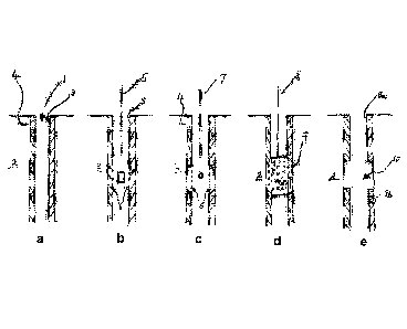
Figure la shows a well casing in situ within a well bore hole;
Figure 1 b shows the well casing perforation stage of the method of the
present invention;
Figure lc shows the jet washing stage of the method of the present invention;
Figure id shows the step of the delivery of chemical heating mixture into and
around the well casing;
-9-
Date Recue/Date Received 2022-07-07
Figure le shows the separate portions of the well casing following the
reaction of the chemical heating mixture within the well bore hole.
Detailed Description of a Preferred Embodiment
So that the general concept of the present invention might be better
understood an
exemplary process of the well casing/tubing disposal method of the present
invention
will be described with reference to Figures la-le.
The skilled person will appreciate from the following description, that
certain steps
shown in the drawings may be omitted without departing from the general
inventive
concept. Further, the skilled person will also appreciate that additional
steps to those
shown may also be used to achieve additional benefits.
Turning now to Figures la, lb, lc, id and le, which show in order the steps
involved
in removing/disposing of a portion of a well casing/tubing so as to create an
exposed
region capable of receiving a well plug that can be used to form a plug across
the
entire cross-section of a well bore hole (i.e. from the rock formation on one
side of
the borehole to the rock formation on the other side of the borehole).
It will be appreciated that although Figures la, 1 b, 1 c, id and le depict
the
application of the clearance method of the present invention to remove a well
casing
and expose the surrounding rock formation the described method can also be
employed to remove tubing other than well casing.
One example of alternative tubing that can be removed using the described
methods
is production tubing. In cases where only the production tubing is to be
removed the
surrounding rock formation does not necessarily need to be exposed.
Figure la shows a well 1 provided in a rock formation 2. The well comprises a
well
casing or other form of tubing 3 formed within a bore hole in the rock
formation 2. In
the region between the rock formation and the casing/tubing 3 is provided an
annulus 4, which may be filled with cement.
-10-
Date Recue/Date Received 2022-07-07
Figure 1 b shows the first stage of the casing/tubing removal method, wherein
a
plurality of perforations 6 are formed in the casing/tubing 3 by way of a
perforating
device 5 that is deliverable down the well 1 using existing delivery means.
Preferably the perforating device 5 is capable of delivering a controlled
explosion
within the region of the casing that is to be perforated. The device 5 is
preferably
capable of perforating the casing in a 3600 target region so that perforations
are
provided around the entire circumference of the casing.
Figure 1 c shows the next stage in the method of the present invention,
wherein a
pressure washing or water jet washing device 7 is delivered down the well 1 to
the
region of the casing in which the perforations 6 were formed. Once again
existing
delivery means can be utilised to deliver the washing device 7 to the target
region
within the well (e.g. cable wire line).
Once the pressure washing or water jet washing device 7 is in position the
device
can be focused towards the perforations 6 in the casing. In this way the
washing
device 7 can be used to clean out or erode the annulus material 4 adjacent to
the
perforated region of the well casing/tubing.
The step of the clearing away a region of annulus material 4 from area
surrounding
the perforated casing is considered to be advantageous because it provides
additional space into which the active chemical agent 9 (see Figure 1d) can be
received. In this way the level of heating applied from the outer surface of
the casing
is enhanced.
It is envisaged that as an alternative, insulating material or a heat drawing
material
(such as DOWTHERM-rm) may be received in the space formed by clearing away the
annulus material with pressure jet washing.
However it is envisaged that, although beneficial, the step of washing out the
region
of annulus material 4 may not be essential in all circumstances; for example
when
the preceding perforating step itself causes the formation of space in the
annulus
material 4 surrounding the casing 3, which further helps to expose the
surrounding
rock formation.
-11-
Date Regue/Date Received 2022-07-07
Figure id shows the step of deploying the active chemical agent 9 to the
perforated
region of the well casing/tubing 3. The active chemical agent 9 is delivered
to the
target region using a delivery tool 8, which is connectable to existing
delivery means;
such as cable wireline.
Depending on which method of the various aspects of the present invention is
being
employed the active chemical agent may be selected from:
= A chemical agent this is capable of reacting with, and thereby consuming,
one
or more chemical components of the well casing;
= A chemical heating and/or cooling means capable of rapidly changing the
temperature within the target region of the well casing;
= A chemical heating mixture.
The delivery tool 8 is capable of carrying the active chemical agent 9 down
the well
to the target region. Once in position the delivery tool 8 can then be
operated to force
the active chemical agent 9 through the perforations 6 in the casing and in to
the
cleared region in the annulus material 4.
In this way both the inside and the outside of the casing/tubing 3 are placed
in
contact with the active chemical agent 9 thereby allowing a more uniform
treatment
of the casing/tubing 3 to be achieved.
It is envisioned that in the case of the chemical heating mixture the active
chemical
agent 9 might advantageously be provided in the form of paste or gel of a
material
such as thermite or thermate so that it can more readily be squeezed through
the
casing perforations 6.
Once the active chemical agent 9 is suitably distributed in and around the
casing/tubing 3 the chemical reaction can be initiated. Depending on the
nature of
the active chemical agent being used this may be done remotely or by way of
timing
device.
As explained above, depending on the type of active chemical agent 9 used the
method of the present invention might facilitate the removal/disposal of the
well
casing by way of: consuming one or more chemical components of the well
casing;
changing the physical properties of the well casing so as to embrittle it
followed by
-12-
Date Recue/Date Received 2022-07-07
targeted physical or environmental stressing; and melting the well casing in
the
target region.
Consumption of the well casing
In the first aspect of the method of the present invention the well
easing/tubing is
broken down by using chemicals that react with materials from which the well
casing
is formed.
In its broadest sense any chemicals that are capable of reacting with the well
casing
in such a way that produces material which is readily cleared from the target
region
(e.g. in the form of gases or powders) to expose the rock formation are
considered
applicable.
One appropriate chemical reaction is considered to be oxidation, wherein the
casing
is effectively consumed or burnt (i.e. like a fuel) rather than melted (i.e.
turned from a
solid state to a liquid state).
In situations where the well casing/tubing has a steel component it is
envisaged that
a process of Iron oxidisation might be employed.
Embrittlement or softening and subsequent removal of the well casina
In a second aspect of the method of the present invention the well
casing/tubing is
again subjected to high temperatures; whether as a consequence of the high
temperatures already present in the down-hole environment or as a result of
n chemical heating means delivered to the target region.
However unlike the melting approach adopted in the third aspect of the present
invention the well casing is subjected to a rapid cooling before melting
occurs.
It is envisaged that the rapid cooling of the well casing (possible using
cooling means
such as liquid nitrogen or cold water) results in a change the structural
orientation of
the metal from which the casing is formed. This can make the casing more
brittle and
susceptible to shattering. Although in the case of well casings/tubings that
are
formed from alloys that have low carbon content the casing/tubing has a
tendency to
soften rather than embrittle. In both cases the rapid temperature changes
transform
the well casing/tubing and make it easier to clear/remove.
-13-
Date Recue/Date Received 2022-07-07
Once the casing has been embrittled the target region can be subjected to
mechanical stresses, such as physical attack or sonic attack. Thus the
weakened
casing is removed by shattering the casing in the targeted region.
Alternatively, once the casing has been softened the target region can be
milled/drilled out using standard milling/drilling equipment. The softened
casing is
much easier, and thus quicker, to remove. An added benefit is achieve by the
softening of the well casing/tubing, in that the sward formed during the
milling/drilling
process is created in smaller more manageable pieces.
It is envisioned that providing the perforations in the well casing enables
the cooling
medium to access both the inside and the outside of the well casing, thus
providing
uniform cooling.
Melting of the well casing
In a third aspect of the method of the present invention the well
casing/tubing is
subjected to high temperatures which melt the target region of the casing. It
is
envisaged that thermite and thermate mixes would be particularly suitable to
achieve
the high melting temperatures of over 1800 C that a-e required.
Unlike in the first and second aspect of the present invention, where it is
considered
merely an beneficial additional step, the step of perforating the well
casing/tubing is
considered essential to this aspect of the invention as it allows the heat to
be applied
zo not only from within the casing but also from outside ¨ thereby maximising
the
destruction of the targeted casing region by melting.
In each of the above approaches a region of the casing/tubing 3 is destroyed
and a
cleared region 10 is created within the well bore hole. Figure le shows the
well hole
1 following one of the above mentioned casing removal stages (i.e. melting;
embrittlement/shattering; burning).
Once created within the well hole the cleared region 10, which extends to the
rock
formation within which the borehole is formed, facilitates a well abandonment
plug to
be deployed therein. The removal of the casing/tubing means that a plug can be
formed which extends across the entire cross-section of the well hole (i.e.
from the
-14-
Date Recue/Date Received 2022-07-07
rock formation on one side of the borehole to the rock formation on the other
side of
the borehole), thus providing a substantial and effective seal.
It is envisioned that the cleared region 10 provided using the method of the
claimed
invention would be suitable for both cement plugs and plugs formed using
eutectic
alloys.
-15-
Date Recue/Date Received 2022-07-07