Note : Les descriptions sont présentées dans la langue officielle dans laquelle elles ont été soumises.
TOWER SECTION AND WIND GENERATING SET
[0001] The present application claims the priority to Chinese Patent
Application No.
202010103876.4, titled "TOWER SECTION AND WIND GENERATING SET", filed on
February 20, 2020, which is incorporated herein by reference its entirety.
FIELD
[0002] The present application relates to the technical field of wind power
generation, and in
particular to a tower section and a wind generating set with the tower
section.
BACKGROUND
[0003] With the development of wind power in deep-water seas, a load to which
a unit is
subjected gradually increases due to the influence of water depth. Compared
with a northern
sea, the load to the unit increases to nearly twice, and a structure of a wind
generating set will
increase correspondingly. However, the trend of offshore wind power grid
parity is increasingly
obvious. In order to reduce the cost, on the one hand, the structural form of
the tower foundation
is changed, and on the other hand, the tower structure is optimized.
[0004] At present, a tower diameter, a flange parameter, the number of bolt
holes and a layout
of an internal structure of a tower are all different in different farms.
Different sizes of the tower
need to be matched with different tower hoisting tools, for turning over and
hoisting, for the
matching of the bolt holes, for the switching of hoisting the towers with
different diameters, for
the eccentricity of the center of gravity inside the tower, and so on.
Therefore, a large number
of tower hoisting tools of different models need to be manufactured.
[0005] Therefore, how to improve the versatility of tower hoisting tools to
reduce costs is an
urgent technical problem in this field.
SUMMARY
[0006] An object according to the present application is to provide a tower
section, through
holes for hoisting lugs to move back and forth are provided in a side wall of
the tower section,
and the hoisting lugs can selectively extend out of the tower section for
hoisting.
19610239.2
34273/124
- 1 -
CA 03168547 2022- 8- 18
[0007] Since the hoisting lugs of the tower section can selectively extend
out, in a wind
generating set provided according to the present application, it does not need
to manufacture
and use a special tower hoisting tool, which can reduce the cost.
[0008] For the objects described above, the following technical solutions are
provided
according to the present application.
[0009] According to an aspect of the present application, a tower section is
provided, which
includes a tower section body and hoisting lugs, through holes are provided in
a side wall of the
tower section body, and an inner cavity of the tower section is in
communication with an
exterior through the through holes; the hoisting lugs are arranged in the
through holes, are
movable along central lines of the through holes, and are movable between a
first position
extending out of the tower section body and a second position retracting into
the tower section
body, to hoist the tower section. Since the hoisting lugs can selectively
extend out, a tower
hoisting tool is not needed to be connected to a flange during the hoisting of
the tower section,
and the hoisting tool is mounted on the hoisting lugs, which does not need to
manufacture and
use a dedicated tower hoisting tool, thereby reducing costs. Furthermore,
since the tower
hoisting tool is not needed to be fixedly connected to the flange, the
assembly and disassembly
time of the tower hoisting tool is saved, and the working efficiency is
improved.
[0010] Specifically, at least two hoisting lugs are provided, each hoisting
lug includes a main
body portion, which is located in the tower section body, and a extending-out
portion, which
extends out of the tower section body, a bearing is sleeved on an outer
circumference of the
extending-out portion, and an outer ring of the bearing rotates around a
central axis of the
hoisting lug, which meets the needs of rotation during the hoisting of the
tower section, avoids
the sliding friction between the sling and the hoisting lug, and thus improves
the service life of
the sling.
[0011] As another embodiment of the present application, each hoisting lug has
a stepped shaft
structure, a diameter of the main body portion is greater than a diameter of
the extending-out
portion, and a projection of the main body portion in a direction
perpendicular to the central
axis of the hoisting lug covers a projection of the outer ring of the bearing
in the direction
perpendicular to the central axis of the hoisting lug.
19610239.2
34273/124
- 2 -
CA 03168547 2022- 8- 18
[0012] As another embodiment of the present application, the tower section
further includes
an end cover, which is connected to an end of the extending-out portion away
from an end of
the main body portion, and a projection of the end cover in the direction
perpendicular to the
central axis of the hoisting lug extends outward from a projection of the
bearing in the direction
perpendicular to the central axis of the hoisting lug. More specifically, the
end cover and the
hoisting lug have a same shape in the direction perpendicular to the central
axis of the hoisting
lug, and a cross section of the hoisting lug in the direction is greater than
a cross section of the
end cover in the direction, so that the end cover closely covers the through
hole in a case that
the extending-out portion of the hoisting lug retracts into the through hole,
so as to prevent
external salt mist and water vapor from entering the tower during the
operation of the wind
generating set. In another aspect, the end cover can limit the sling wound
around an outer
circumference of the extending-out portion in a case that the extending-out
portion of the
hoisting lug extends out of the through hole, so as to prevent the sling from
falling off from the
end cover, thereby further improving the safety. More preferably, the cross
section of the end
cover in the direction perpendicular to the central axis of the hoisting lug
is circular.
[0013] As another embodiment of the present application, a sealing member is
provided
between the end cover and the hoisting lug, and the sealing member is
retracted into the through
hole for sealing in the case that the extending-out portion of the hoisting
lug retracts into the
through hole, which further improves the sealing performance of the tower
section.
[0014] As another embodiment of the present application , the tower section is
cylindrical, the
central axis of each hoisting lug extends along a radial direction of the
tower section, and at
least two hoisting lugs are spaced apart at a predetermined angle along a
circumferential
direction of the tower section.
[0015] As another embodiment of the present application, at least two hoisting
lugs are
provided along an axial direction of the tower section body, and at least two
hoisting lugs are
spaced apart at the predetermined angle along a circumferential direction of
the tower section
body atwhich each hoisting lug is located, so as to facilitate the horizontal
hoisting of the tower
section.
[0016] Furthermore, the tower section further includes a guiding member which
is coaxially
arranged with the through hole, the guiding member is fixed to the tower
section body, a guiding
19610239.2
34273/124
- 3 -
CA 03168547 2022- 8- 18
groove is provided in one of an inner wall of the guiding member and an outer
circumference
of the hoisting lug, a sliding block which is matched with the guiding groove
is provided in the
other one of the inner wall of the guiding member and the outer circumference
of the hoisting
lug, and the sliding block is slidable in the guiding groove.
[0017] According to another exemplary embodiment of the present application, a
limiting
block is formed at an end of the main body portion away from the extending-out
portion, and
the limiting block is formed by protruding outward from an outer circumference
of the main
body portion, so as to be capable of being clamped at an end of the guiding
member.
[0018] According to another embodiment of the present application, the tower
section further
includes a spring locking pin, which is pre-embedded in one of the outer
circumference of the
main body portion and an inner cavity of the guiding member, a groove, which
is matched with
the spring locking pin, is provided in the other one of the outer
circumference of the main body
portion and the inner cavity of the guiding member, and the spring locking pin
is selectively
fixed in the groove.
[0019] Furthermore, the tower section further includes a supporting platform,
which is fixed
to an inner chamber of the tower section, the guiding member is fixed to the
supporting platform,
a driving member is a hydraulic cylinder, one of a cylinder body and a
cylinder rod of the
hydraulic cylinder is connected to the hoisting lug, and the other one of the
cylinder body and
the cylinder rod of the hydraulic cylinder is connected to the supporting
platform, the hydraulic
cylinder is connected to the main body portion to drive the hoisting lug to
move into the through
hole, so that the extending-out portion can selectively extend out of the
tower section for
hoisting.
[0020] According to another aspect of the present application, a wind
generating set is
provided, which includes the tower section provided according to the present
application.
[0021] The tower section and the wind generating set provided according to the
present
application have at least the following beneficial effects: the tower section
provided according
to the present application includes the hoisting lug that is movable along a
direction of a
centerline of the through hole of the tower section body, and a second end of
the hoisting lug
can extend out of the tower section for hoisting in a case that the tower
section needs to be
19610239.2
34273/124
- 4 -
CA 03168547 2022- 8- 18
hoisted. Due to the existence of the hoisting lug, there is no need to
manufacture and use a
dedicated tower hoisting tool, thereby reducing the cost.
BRIEF DESCRIPTION OF THE DRAWINGS
[0022] The above and other objects and features of the present application
will become clearer
through the following description of the embodiments in conjunction with the
drawings.
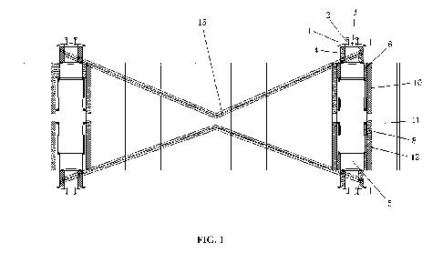
[0023] FIG. 1 is structural view of a tower section in a hoisting state
according to a specific
embodiment of the present application;
[0024] FIG. 2 is an enlarged view of the tower section in FIG. 1;
[0025] FIG. 3 is a partial enlarged view of the tower section in FIG. 2 in a
case that a hoisting
lug retracts into a through hole;
[0026] FIG. 4 is a structural view showing a state before an end cover of the
tower section
abuts against the tower section body in FIG. 1;
[0027] FIG. 5 is a structural view of the hoisting lug in FIG. 1;
[0028] Figure 6 is a structural view of the end cover in FIG. 1; and
[0029] FIG. 7 is a structural view of the tower section in another hoisting
state in FIG. 1,
[0030] Reference numerals in the drawings:
1: end cover; 2: fastener;
3: sealing member; 4, bearing;
5: hoisting lug; 6: guiding member;
7: first mounting seat; 8: cylinder body;
9: second mounting seat; 10: supporting platform;
11: tower section body; 12: cylinder rod;
13: hoisting beam assembly; 15: sling;
16: wind cable; 17: threaded hole.
19610239.2
34273/124
- 5 -
CA 03168547 2022- 8- 18
DETAILED DESCRIPTION OF THE EMBODIMENTS
[0031] Exemplary implementations are now described more comprehensively with
reference
to the accompanying drawings. However, the examples of implementations may be
implemented in multiple forms, and it is not to be understood as being limited
to the
embodiments described herein. Conversely, the implementations are provided to
make the
present application more comprehensive and complete, and comprehensively
convey the idea
of the examples of the implementations to a person skilled in the art. The
same reference
numerals in the drawings denote the same or similar structures, and thus their
detailed
descriptions will be omitted.
[0032] A wind generating set includes a tower, a wind generator, which is
supported on a top
of the tower, a wind wheel and other components. The tower includes multiple
tower sections
which are stacked from top to bottom, and a specific structure of the tower
section is described
below.
[0033] Referring to FIGS. 1 to 7, in an exemplary embodiment of the tower
section according
to the present application, the tower section includes a tower section body
11, at least two
hoisting lugs 5 and a driving member. Through holes are provided in a side
wall of the tower
section body 11, and an inner cavity of the tower section body 11 is in
communication with an
exterior through the through holes. The hoisting lugs 5 can be arranged in the
through holes,
and be movable along directions of centerlines of the through holes. The
driving member can
be arranged in the inner cavity of the tower section body 11, and the driving
member can be
connected to the hoisting lug 5 to drive the hoisting lug 5 to move back and
forth between a
first position and a second position, where a part of the hoisting lug 5
extends out of the tower
section body 11 for hoisting in a case that the hoisting lug 5 is in the first
position, and the
hoisting lug 5 retracts into the through hole of the tower section body 11 in
a case that the
hoisting lug 5 is in the second position.
[0034] The hoisting lug 5 of the tower section according to the present
application can
selectively extend out of the tower section body 11 as needed. For example, a
part of the hoisting
lug 5 can extend out of the tower section body 11 in a case that the tower
section needs to be
hoisted, so as to facilitate of being connected to a sling 15. Due to the
existence of the hoisting
lugs 5, it does not need a flange bolt of the tower in order to connect the
tower section to a tower
19610239.2
34273/124
- 6 -
CA 03168547 2022- 8- 18
hoisting tool, which simplifies the mounting process of the tower hoisting
tool and improves
the work efficiency. In another aspect, the tower section does not need to be
matched with a
special tower hoisting tool, which reduces the cost.
[0035] Referring to the figures, the tower section provided according to the
present application
includes two hoisting lugs 5, but is not limited thereto. Those skilled in the
art can select the
number of the hoisting lugs 5 as needed.
[0036] Each hoisting lug 5 includes a main body portion, which is located in
the tower section
body 11, and an extending-out portion, which is connected to the main body
portion and is able
to extend out of the tower section body 11, a bearing 4 is sleeved on an outer
circumference of
the extending-out portion, and an outer ring of the bearing 4 is rotatable
around a central axis
of the hoisting lug 5, which meets the needs of rotation during hoisting of
the tower section,
avoids the sliding friction between the sling 15 and the hoisting lug 5, and
thus improves the
service life of the sling 15. A separate driving member can be provided to
drive the bearing to
rotate. Of course, the bearing 4 may not be provided on the outer
circumference of the
extending-out portion, which is also within the protection scope of the
present application.
[0037] As another embodiment of the present application, each hoisting lug 5
has a stepped
shaft structure, an area of a cross section of the main body portion is
greater than an area of a
cross section of the extending-out portion, and a projection of the main body
portion in a
direction perpendicular to the central axis of the hoisting lug covers a
projection of the outer
ring of the bearing 4 in the direction perpendicular to the central axis of
the hoisting lug 5, so
that the extending-out portion can retract into the through hole. The cross
section of the hoisting
lug 5 can be oval, rectangular, triangular, etc.. In this embodiment, the
cross section of the
hoisting lug 5 is circular, and a diameter of the main body portion is greater
than a diameter of
the extending-out portion, and a diameter of the out ring of the bearing 4 is
not greater than the
diameter of the main body portion.
[0038] As another embodiment, the tower section further includes an end cover
1, which is
connected to an end of the extending-out portion away from an end of the main
body portion,
so that the end cover 1 closely covers the through hole in the case that the
extending-out portion
of the hoisting lug 5 retracts into the through hole, so as to prevent
external salt mist and water
vapor from entering the tower during the operation of the wind generating set.
In addition, the
19610239.2
34273/124
- 7 -
CA 03168547 2022- 8- 18
end cover 1 can limit the sling 15 during the hoisting process of the tower
section, so as to
prevent the sling 15 from falling off from the hoisting lug 5, thereby further
improving the
safety of the operation. Specifically, a cross section of the end cover 1 in
the direction
perpendicular to the central axis of the hoisting lug 5 is rectangular,
elliptical or triangular.
Preferably, the cross section of the end cover 1 is circular, and a diameter
of the cross section
of the end cover 1 is greater than the diameter of the main body portion of
the hoisting lug 5.
More preferably, an arc concave chamber is formed at an end of the end cover
lfacing the
hoisting lug 5, so that the end cover 1 closely abuts against an outer
circumferential surface of
the tower section.
[0039] The end cover 1 is arranged on an end surface of the extending-out
portion by a fastener
2. For example but not limited to, a mounting through hole for the fastener 2
to pass through is
provided in the end cover 1, a threaded hole 17 which is matched with an
external thread of the
fastener 2 is provided on the end surface of the extending-out portion of the
hoisting lug 5, and
the end cover 1 is fixed to the hoisting lug 5 by inserting the fastener 2
into the mounting through
hole and screwing it into the threaded hole 17.
[0040] Referring to the figures, a sealing member 3 is provided between the
end cover 1 and
the hoisting lug 5, and the sealing member 3 can retract into the through hole
for sealing in the
case that the extending-out portion of the hoisting lug 5 retracts into the
through hole, or the
sealing member 3 closes abuts against an outer circumference of the through
hole, which further
improves the sealing performance of the tower section. Referring to FIG. 3, in
this embodiment,
a cross section of the sealing member 3 in the direction perpendicular to the
center axis of the
hoisting lug 5 may be circular, and a diameter of the sealing member 3 can be
greater than a
diameter of the through hole. Furthermore, the sealing member 3 can be
arranged to taper from
the center to an edge, so as to facilitate sealing. In actual, a sealing
member mounting hole,
which is matched with the threaded hole 17, is provided on the sealing member
3 for the fastener
2 to pass through.
[0041] Preferably, the tower section is cylindrical, the central axis of the
hoisting lug 5 extends
along a radial direction of the tower section, and at least two hoisting lugs
5 are spaced apart at
a predetermined angle along a circumferential direction of the tower section,
that is, two
hoisting lugs 5 are provided in this embodiment and both extend along a
diameter of the tower
section. It can be understood that three hoisting lugs 5 can be provided and
be equally spaced
19610239.2
34273/124
- 8 -
CA 03168547 2022- 8- 18
apart at an angle of 120 degrees on a same circumference of the tower section
body 11. Certainly,
four hoisting lugs 5 may be provided and be equally spaced apart at an angle
of 90 degrees on
a same circumference of the tower section body 11, and so on, which will not
be repeated herein.
[0042] More preferably, at least two hoisting lugs 5 are provided along an
axial direction of
the tower section body 11, so as to horizontally hoist the tower section.
Specifically, referring
to FIG. 1, two sets of hoisting lugs 5 are provided along the axial direction
of the tower section
body 11, for example, the hoisting lugs 5 on the left side in FIG. 1 are
referred as the left hoisting
lugs, and the hoisting lugs 5 on the right side in FIG. 1 are referred as the
right hoisting lugs.
Two left hoisting lugs and two right hoisting lugs are respectively provided,
and are spaced
apart at an angle of 180 degrees along a circumferential direction of the
tower section body 11,
and a line segment formed by the position at which one left hoisting lug is
and the position at
which one right hoisting lug is parallel to an central axis of the tower
section body 11. During
the horizontal hoisting process of the tower section, the sling 15 can be
connected to both one
left hoisting lug and one right hoisting lug which are located on the straight
line segment,
respectively. Of course, it can be understood that the other sling 15 is also
connected to both
the other left hoisting lug and the other right hoisting lug, so that the
tower section can be hoisted
horizontally. Referring to the figure, furthermore, the tower section further
includes a
supporting platform 10, which is fixed to the inner cavity of the tower
section body 11, and a
guiding member 6, which is coaxially arranged with the through hole, where the
guiding
member 6 is fixed to the supporting platform 10, and the hoisting lug 5 can be
connected to the
tower section body 11 through the guiding member 6. Specifically, the guiding
member 6 is
sleeved into the through hole, and an end of the guiding member 6 facing the
end cover 1 is
matched with an outer circumference of the tower section.
[0043] A guiding groove is provided in one of an inner wall of the guiding
member 6 and an
outer circumference of the hoisting lug 5, a sliding block, which is matched
with the guiding
groove, is provided in the other one of the inner wall of the guiding member 6
and the outer
circumference of the hoisting lug, and the sliding block is slidable in the
guiding groove. In
addition, an extending direction of the guiding groove is substantially
parallel to the central axis
of the hoisting lug 5. In this embodiment, the inner wall of the guiding
member 6 is recessed to
form the guiding groove, the outer circumference of the hoisting lug 5 is
protruded to form the
sliding block, and the hoisting lug 5 is movable along a direction of a
centerline of the through
19610239.2
34273/124
- 9 -
CA 03168547 2022- 8- 18
hole by sliding the sliding block in the guiding groove. The guiding member 6
can also be fixed
on the tower section body 11 by means of other structures.
[0044] The supporting platform 10 provided in this embodiment may be a
supporting platform
which has been provided in the tower section for operation and maintenance
personnel, so that
the number of supporting platforms can be decreased, the material consumption
of the entire
tower section can be reduced, and the manufacturing cost can be reduced. The
supporting
platform 10 may also be the supporting platform which is mounted for
cooperating with the
hoisting lug 5. Preferably, the supporting platform 10 may be in a frame
structure in order to
reduce the weight of the tower section.
[0045] Referring to the figure, the driving member may be a hydraulic
cylinder, an air cylinder
or other electric pushing rods, and the driving member being a hydraulic
cylinder is taken as an
example in this embodiment. A first mounting seat 7 is provided at the end of
the main body
portion of the hoisting lug 5, a second mounting seat 9 is fixed to the
supporting platform 10,
and two ends of the hydraulic cylinder are hinged to the first mounting seat 7
and the second
mounting seat 9 respectively. Specifically, a cylinder body 8 of the hydraulic
cylinder is
connected to the supporting platform 10, a cylinder rod 12 of the hydraulic
cylinder is connected
to the main body portion of the hoisting lug 5, to drive the hoisting lug 5 to
move in the through
hole by the relative sliding movement of the cylinder rod 12 within the
cylinder body 8, so that
the extending-out portion can selectively extend out of the tower section for
hoisting.
[0046] According to another exemplary embodiment of the present application, a
limiting
block is formed at an end of the main body portion away from the extending-out
portion, and
the limiting block is formed by protruding outward from an outer circumference
of the main
body portion, so as to be capable of being clamped at an end of the guiding
member 6. One,
two or more limiting blocks may be provided to be circumferentially arranged
on a same
circumference of the main body portion, so as to limit the movement of the
hoisting lug 5,
preventing the hoisting lug 5 from falling off from the through hole and
improve the safety of
the tower section. The first mounting seat 7 may be provided on the limiting
block, as shown in
FIG. 2 and FIG. 3. Two limiting blocks may be provided as needed, and be
uniformly arranged
on the circumference of the main body portion.
19610239.2
34273/124
- 10 -
CA 03168547 2022- 8- 18
[0047] As another embodiment, the tower section further includes a spring
locking pin (not
shown) which is pre-embedded in one of the outer circumference of the main
body portion and
an inner cavity of the guiding member 6, a groove (not shown) which is matched
with the spring
locking pin is provided in the other one of the outer circumference of the
main body portion
and the inner cavity of the guiding member 6, and the spring locking pin is
selectively fixed in
the groove. During the movement of the hoisting lug 5 along the direction of
the centerline of
the through hole, a pin of the spring locking pin can be fixed in the groove
under the elastic
force of the spring in a case that the spring locking pin matches a position
of the groove, so as
to lock the hoisting lug 5 for hoisting. After the hoisting is completed, the
driving member can
reversely drive the spring locking pin to move as the hoisting lug 5 is
required to retract into
the through hole, so that the spring locking pin is separated from the groove,
thereby unlocking.
[0048] During the inverted transportation of the tower section, a crane is
connected to the
hoisting lugs 5 on two sides of the tower section through two slings 15, which
can be directly
hooked, unloaded and transported invertedly, and realize the non-vertical
hoisting of the slings
15, such as but not limited to the inverted-V shaped hoisting, so that the
center of gravity of the
tower is biased to one side to reduce the risk of hoisting.
[0049] During the hoisting of the tower section, the turnover of the tower
section can be
realized with the help of a hoisting beam assembly 13. Specifically, one end
of the sling 15 is
connected with the hoisting beam assembly 13, and the other end is sleeved on
the outer
circumference of the bearing 4 of the extending-out portion of the hoisting
lug 5, which can
realize the transformation between the vertical state and the horizontal state
of the tower section.
After the tower section is changed into the vertical state from the horizontal
state and is
connected to a lower tower section, the hook is slowly released, and the sling
15 is in a loose
state, and the automatic decoupling action of the sling can be realized by
pulling outward with
a wind cable 16.
[0050] At present, in order to hoist different types of tower sections,
multiple hoisting points
need to be provided on the hoisting beam to keep the sling extending
vertically in the hoisting
process of the tower section, so as to prevent the interference between the
sling and the tower
section. Since the tower section provided according to the present application
has hoisting lugs
5 that can extend outward, there is no interference between the sling and the
tower section
during the hoisting of the tower section, and the non-vertical hoisting of the
sling can be realized.
19610239.2
34273/124
- 11 -
CA 03168547 2022- 8- 18
For example but not limited to, the sling can be hoisted in an inverted-V
shape. In addition, due
to the existence of the hoisting lug 5, there is no need to match the special
hoisting tool to
connect with the flange bolt of the tower section, which solves the problem
that the tower
hoisting tool is not universal, thus reducing the cost, simplifying the
mounting process of the
hoist, and improving the work efficiency. The hoisting lug 5 is arranged to
selectively extend
out of the tower section, which can realize the simple transition between
hoisting conditions
and non-hoisting conditions, with simple structure and easy operation.
[0051] Furthermore, the bearing 4 is sleeved on the extending-out portion of
the hoisting lug
5, which can avoid the friction damage of the hoisting lug 5 to the sling
during the hoisting, so
as to improve the service life of the sling and further improve the safety of
the tower section.
[0052] Since the sealing member 3 can cover the outer circumference of the
through hole, or
cover an outer circumference of the through hole of the guiding member 6, the
inner cavity of
the tower section can be isolated from the exterior in the case that the
hoisting lug 5 retracts
into the through hole, which can prevent the external salt mist or wet gas
from entering the
tower section, and improve the sealing performance and safety of the tower
section.
[0053] In addition, the described characteristics, structures, or features
according to the
present application may be combined in one or more embodiments in any
appropriate manner.
In the above descriptions, a lot of specific details are provided to give a
comprehensive
understanding of the embodiments of the present application. However, a person
of ordinary
skill in the art is to be aware that, the technical solutions in the present
application may be
implemented without one or more of the particular details, or another method,
component, or
material may be used. In other cases, well-known structures, materials, or
operations are not
shown or described in detail, in order not to obscure the aspects of the
present application.
19610239.2
34273/124
- 12 -
CA 03168547 2022- 8- 18