Note : Les descriptions sont présentées dans la langue officielle dans laquelle elles ont été soumises.
[DESCRIPTION]
[Invention Title]
PUMP DISPENSER
[Technical Field]
5 The present invention relates to a pump dispenser, and more
particularly, to a
pump dispenser in which a deformation prevention locking part guides a chaplet
to
move in an axial direction of a housing, thereby allowing or restricting a
pressing
operation of a head part while preventing deformation of an elastic member.
[Background Art]
10 Generally, pump dispensers are devices for discharging a predetermined
amount of content stored inside a container by a pressing force, and pump
dispensers
are known to be applied to various types of containers for storing cosmetics,
perfumes, medicines, food, and the like.
In such a pump dispenser, when a user presses a head part, a shaft is lowered
15 against an elastic force of an elastic member and the content contained
in a housing
is discharged to a nozzle through a through-hole and a connecting pipe. In
addition,
when the user releases the head part, the shaft rises with the elastic force
of the
elastic member, the through-hole is closed to block the content, and a vacuum
is
formed inside the housing, and thus the content contained in the container
fills the
20 housing.
However, in the conventional pump dispenser, since a metallic coil elastic
member is built into the housing into which the content is introduced, there
is a
problem in that the coil elastic member is always in contact with the content,
and
thus the coil elastic member may be corroded or deformed and the content may
be
25 altered due to a chemical reaction between the coil elastic member and
the content.
1
CA 03169016 2022- 8- 22
Further, when the conventional pump dispenser is distributed while the head
part is constrained to the housing to prevent a pressing operation of the head
part,
there is a problem in that, since the elastic member is left in a compressed
state for a
long time, the elastic force of the elastic member is degraded.
5 Therefore, there is a need to solve the above problems.
As a related art, Korean Patent Registration No. 10-1107519 (Registered on
J anuary 12, 2012, Title: Fluid Pump Dispenser) is disclosed.
[Disclosure]
[Technical Problem]
10 The present
invention is directed to providing a pump dispenser in which a
deformation prevention locking part guides a chaplet to move in an axial
direction of
a housing, thereby allowing or restricting a pressing operation of a head part
while
preventing deformation of an elastic member.
[Technical Solution]
15 One aspect
of the present invention provides a pump dispenser including a
cap part fastened to a container, a housing which is provided at the cap part
and in
which a content stored in the container remains and is dischargeable, a shaft
which is
accommodated in the housing to be movable in an axial direction of the housing
and
includes a head part for discharging the content remaining in the housing
outward
20 through a
pressing operation by an external force, a chaplet that is provided in the
housing for the shaft to be inserted to pass through the housing and allows or
blocks
movement of the shaft on a basis of a rotation angle of the head part, an
elastic
member that is provided on a circumferential surface of the shaft and
elastically
supports the chaplet and the head part, and a deformation prevention locking
part that
25 guides the
chaplet to move in the axial direction of the housing at the time of rotation
2
CA 03169016 2022- 8- 22
of the head part and allows or restricts the pressing operation of the head
part while
preventing deformation of the elastic member.
The head part may be inserted or prevented from being inserted in an axial
direction of the chaplet on the basis of the rotation angle by a rotation
insertion guide
5 part, and the rotation insertion guide part may include a slide
protrusion formed to
protrude from a circumferential surface of the head part, a slide groove
formed to be
recessed in the axial direction in an inner surface of the chaplet for the
slide
protrusion to be slidably fitted in the chaplet, and a locking support groove
formed to
communicate with an end part of the slide groove in a circumferential
direction and
10 configured to lock and support the slide protrusion.
The deformation prevention locking part may include a helical groove formed
in an inner surface of the housing to be recessed in a helical trace, and a
moving
protrusion formed to protrude from a circumferential surface of the chaplet to
be
movably fitted in the helical groove.
15 A locking member may be formed to protrude from the helical groove such
that the moving protrusion is allowed to be moved by an external force greater
than
or equal to a set force.
An inflow prevention part may prevent the content from flowing between the
housing and the chaplet, and the inflow prevention part may include a
plurality of
20 close-contact moving protrusions formed on the circumferential surface
of the
chaplet to be movable while in close contact with an inner surface of the
housing,
and a pressure guide part configured to guide the chaplet to press the housing
when
the chaplet is moved to restrict the pressing operation of the head part.
The elastic member may include a first support ring configured to be
25 accommodated and supported in the chaplet, a second support ring spaced
apart from
3
CA 03169016 2022- 8- 22
the first support ring and configured to support the head part to be pressed,
and a
uniform elasticity forming part provided between the first support ring and
the
second support ring and configured to form a uniform elastic restoring force
when
the head part is pressed by the external force.
5 The uniform elasticity forming part may include a plurality of
elasticity
providing parts vertically disposed between the first support ring and the
second
support ring to provide an elastic force, wherein pairs of the elasticity
providing parts
cross obliquely, and posture maintaining parts which are horizontally
connected to
parts adjacent to the vertically disposed elasticity providing parts, and that
move
10 vertically to vary inclinations of the elasticity providing parts such
that a posture is
maintained when a pressing force is applied to the second support ring.
[Advantageous Effects]
A pump dispenser according to the present invention has a structure in which
a deformation prevention locking part guides a chaplet to move in an axial
direction
15 of a housing, thereby allowing or restricting a pressing operation of a
head part while
preventing deformation of an elastic member, and thus an elastic force of the
elastic
member can be maintained even when the elastic member is left for a long time
while the pressing operation of the head part is restricted in the
distribution process,
thereby improving durability.
20 [Description of Drawings]
FIG. 1 is a perspective view illustrating a pump dispenser according to an
embodiment of the present invention.
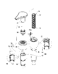
FIG. 2 is an exploded perspective view illustrating the pump dispenser
according to the embodiment of the present invention.
4
CA 03169016 2022- 8- 22
FIG. 3 is a cross-sectional view illustrating the pump dispenser according to
the embodiment of the present invention.
FIG. 4 is a cross-sectional view illustrating an elastic member in the pump
dispenser according to the embodiment of the present invention.
5 FIG. 5 is a
side view illustrating a modified example of the elastic member in
the pump dispenser according to the embodiment of the present invention.
FIG. 6 is a side view illustrating another modified example of the elastic
member in the pump dispenser according to the embodiment of the present
invention.
FIG. 7 is an operational view illustrating an operating state of a rotation
10 insertion
guide part in the pump dispenser according to the embodiment of the
present invention.
FIG. 8 is an operational view illustrating an operating state of a deformation
prevention locking part in the pump dispenser according to the embodiment of
the
present invention.
15 FIG. 9 is an
exploded perspective view illustrating main parts in a modified
example of a shaft and a chaplet in the pump dispenser according to the
embodiment
of the present invention.
[Modes of the Invention]
Hereinafter, embodiments of a pump dispenser according to the present
20 invention
will be described with reference to the accompanying drawings. In this
process, thicknesses of lines, sizes of components, and the like illustrated
in the
drawings may be exaggerated for clarity and convenience of description.
Further, some terms which will be described below are defined in
consideration of functions in the present invention and meanings may vary
25 depending
on, for example, a user or operator's intentions or customs. Therefore,
CA 03169016 2022- 8- 22
the meanings of these terms should be interpreted based on the scope
throughout this
specification.
FIG. 1 is a perspective view illustrating a pump dispenser according to an
embodiment of the present invention, FIG. 2 is an exploded perspective view
5 illustrating the pump dispenser according to the embodiment of the
present invention,
FIG. 3 is a cross-sectional view illustrating the pump dispenser according to
the
embodiment of the present invention, FIG. 4 is a cross-sectional view
illustrating an
elastic member in the pump dispenser according to the embodiment of the
present
invention, FIG. 5 is a side view illustrating a modified example of the
elastic member
10 in the pump dispenser according to the embodiment of the present
invention, FIG. 6
is a side view illustrating another modified example of the elastic member in
the
pump dispenser according to the embodiment of the present invention, FIG. 7 is
an
operational view illustrating an operating state of a rotation insertion guide
part in the
pump dispenser according to the embodiment of the present invention, FIG. 8 is
an
15 operational view illustrating an operating state of a deformation
prevention locking
part in the pump dispenser according to the embodiment of the present
invention, and
FIG. 9 is an exploded perspective view illustrating main parts in a modified
example
of a shaft and a chaplet in the pump dispenser according to the embodiment of
the
present invention.
20 As illustrated in FIGS. 1 to 9, the pump dispenser according to the
embodiment of the present invention includes a cap part 10, a housing 20, a
shaft 30,
a chaplet 40, an elastic member 50, and a deformation prevention locking part
60.
The cap part 10 is a component fastened to a container in which the content is
stored, and has a through-hole 11 which is formed therein so that a head part
31 of
25 the shaft 30 is movably inserted.
6
CA 03169016 2022- 8- 22
The housing 20 is provided in the cap part 10 to be accommodated in the
container and allows the content stored in the container to remain therein to
be
discharged. The housing 20 is formed to have a hollow pipe and includes an
opening and closing valve 21 that opens and closes a passage so that the
content
5 stored in the container is suctioned to remain therein when the shaft 30
is moved.
In addition, the shaft 30 is movably accommodated in the housing 20 in an
axial direction and includes the head part 31 that discharges the content
remaining in
the housing 20 outward through a pressing operation by an external force.
That is, when the pressing operation of the head part 31 is performed, the
10 shaft 30 is moved toward the container to suction the content remaining
in the
housing 20 and then discharges the content to the outside through a nozzle 31a
of the
head part 31, and when the pressing operation of the head part 31 stops, the
shaft 30
is moved and restored by the elastic member 50.
To this end, a piston 32 that selectively opens or closes a flow path so that
the
15 content remaining in the housing 20 is introduced is provided on a
circumferential
surface of the shaft 30.
Meanwhile, the chaplet 40 is provided in the housing 20 so that the shaft 30
may be inserted to pass therethrough, and allows or blocks the movement of the
shaft
30 on the basis of a rotation angle of the head part 31.
20 In this case, the head part 31 may be inserted or prevented from being
inserted in the axial direction of the chaplet 40 by the rotation insertion
guide part 70
on the basis of the rotation angle. The rotation insertion guide part 70
includes a
slide protrusion 71 that is formed to protrude from a circumferential surface
of the
head part 31, a slide groove 72 that is formed to be recessed in the axial
direction in
25 an inner surface of the chaplet 40 such that the slide protrusion 71 is
slidably fitted
7
CA 03169016 2022- 8- 22
therein, and a locking support groove 73 that is formed to communicate with an
end
part of the slide groove 72 in a circumferential direction and locks and
supports the
slide protrusion 71.
That is, when the head part 31 is rotated so that the slide protrusion 71 is
5 positioned in the locking support groove 73, the head part 31 cannot
perform the
pressing operation and thus the head part 31 may be prevented from being
inserted in
the axial direction of the chaplet 40, and when the head part 31 is rotated so
that the
slide protrusion 71 is positioned in the slide groove 72, the head part 31 can
perform
the pressing operation and thus the head part 31 may be restorably inserted in
the
10 axial direction of the chaplet 40.
In addition, an inflow prevention part 80 may prevent the content from
flowing between the housing 20 and the chaplet 40. Here, the inflow prevention
part 80 includes a plurality of close-contact moving protrusions 81 formed on
a
circumferential surface of the chaplet 40 to be movable while in close contact
with
15 an inner surface of the housing 20, and a pressure guide part 82 that
guides the
chaplet 40 to press the housing 20 when the chaplet 40 is moved to restrict
the
pressing operation of the head part 20.
In this case, the pressure guide part 82 includes an inclined part 82a which
is
formed on the inner surface of the housing 20 and along which an inner
diameter of
20 the housing 20 is decreased, and a pressing jaw part 82b formed on the
circumferential surface of the chaplet 40 to forcibly press the inclined part
82.
In addition, the elastic member 50 is disposed on the circumferential surface
of the shaft 30 to be accommodated in the chaplet 40, and elastically supports
the
chaplet 40 and the head part 31. The elastic member 50 serves to provide an
elastic
25 force to the head part 31 such that when the pressing operation is
removed in a state
8
CA 03169016 2022- 8- 22
in which the shaft 30 is moved toward the container by the pressing operation
of the
head part 31, the shaft 30 is moved and restored.
Specifically, as illustrated in FIG. 4, the elastic member 50 includes a first
support ring 51 that can be mounted on the chaplet 40 and is supported on the
chaplet
5 40, a second
support ring 52 which is spaced apart from the first support ring 51 and
supports the head part 31 to be pressed, and a uniform elasticity forming part
53
which is provided between the first support ring 51 and the second support
ring 52 to
form a uniform elastic restoring force when the head part 31 is pressed by an
external
force.
10 In this
case, the uniform elasticity forming part 53 includes a plurality of
elasticity providing parts 53a vertically disposed between the first support
ring 51
and the second support ring 52 to provide an elastic force, wherein pairs of
the
elasticity providing parts 53a cross obliquely, and posture maintaining parts
53b
which are horizontally connected to parts adjacent to the vertically disposed
elasticity
15 providing
parts 53a, and that move vertically to vary inclinations of the elasticity
providing parts 53a such that a posture is maintained when a pressing force is
applied
to the second support ring 52.
That is, when the pressing force is applied to the head part 31 so that the
second support ring 52 is moved toward the first support ring 51, the posture
20 maintaining
part 53b receives a load applied to the second support ring 52, is
vertically moved together with the second support ring 52 while the posture is
maintained, and varies the inclinations of the elasticity providing parts 53a
to
gradually become gentle. Conversely, when the pressing force applied to the
head
part 31 is removed in a state in which the second support ring 52 is moved
toward the
25 first
support ring 51, the elasticity providing parts 53a allow the posture
maintaining
9
CA 03169016 2022- 8- 22
parts 53b to be vertically moved such that the inclinations are changed by a
restoring
force to become steep and the posture maintaining parts 53b return to the
original
positions.
Accordingly, in the process in which the second support ring 52 is moved
5 toward the first support ring 51 by the pressing force applied to the
head part 31, the
center of gravity is prevented from being biased to either side, and thus it
is possible
to smoothly guide the elastic movement of the head part 31 for pumping action.
In this case, as illustrated in FIG. 5, the uniform elasticity forming part 53
further includes first posture maintaining and reinforcing parts 53c which are
10 provided in a circular trace at parts of the elasticity providing parts
53a facing the
posture maintaining parts 53b in the horizontal direction and disperse the
load
transmitted to the posture maintaining parts 53b to reinforce the vertical
movement
posture of the posture maintaining parts 53b.
As a result, since the load applied to the second support ring 52 is dispersed
15 to the posture maintaining parts 53b and the first posture maintaining
and reinforcing
parts 53c by the pressing of the head part 31, the elastic member 50 may be
prevented from being bent in the process of being contracted or extended, and
thus
may provide a more stable and uniform elastic force.
Further, as illustrated in FIG. 6, the uniform elasticity forming part 53
further
20 includes second posture maintaining and reinforcing parts 53d which are
provided at
parts where the posture maintaining parts 53b are vertically spaced apart from
each
other to be elastically deformed and curved by the load transmitted to the
posture
maintaining parts 53b and to reinforce the vertical movement posture of the
posture
maintaining parts 53b.
CA 03169016 2022- 8- 22
That is, when the posture maintaining parts 53b are moved toward the first
support ring 110 so that the inclinations of the elasticity providing parts
53a become
gradually gentler, the second posture maintaining and reinforcing parts 53d
are
deformed to be curved, and are restored while the vertical separation distance
of the
5 posture maintaining parts 53b is maintained, at the moment when the
pressing force
applied to the head part 31 is removed. Accordingly, the elastic member 50 may
be
prevented from being twisted or bent in the process of being contracted or
extended.
Meanwhile, a material of the elastic member 50 is not limited, but it is
advantageous for it to be injection molded with a material of a synthetic
resin instead
10 of a metal material. Therefore, it is possible to prevent deterioration
of the content
due to corrosion and to improve the convenience of use because there is no
need to
separate the content during recycling.
The deformation prevention locking part 60 guides the chaplet 40 to move in
the axial direction of the housing 20 when the head part 31 is rotated, and
allows or
15 restricts the pressing operation of the head part 31 while preventing
the deformation
of the elastic member 50.
To this end, the deformation prevention locking part 60 includes a helical
groove 61 formed in the inner surface of the housing 20 to be recessed in a
helical
trace, and a moving protrusion 62 formed to protrude from the circumferential
20 surface of the chaplet 40 to be movably fitted in the helical groove 61.
That is, when the moving protrusion 62 is rotated and moved toward the
container along the helical groove 61 due to the rotation of the head part 31,
the head
part 31 is accommodated in the housing 20, and thus the pressing operation of
the
head part 31 cannot be performed, and when the moving protrusion 62 is rotated
and
11
CA 03169016 2022- 8- 22
moved toward the head part 31 along the helical groove 61 due to the rotation
of the
head part 31, the pressing operation of the head part 31 can be performed.
In this case, a locking member 61a may be formed to protrude from the
helical groove 61 such that the moving protrusion 62 may be moved by an
external
5 force
greater than or equal to a set force. As a result, the head part 31 may be
prevented from being arbitrarily rotated due to an external force less than or
equal to
the set force while protruding from the housing 20.
Meanwhile, as illustrated in FIG. 9, the shaft 30 may be formed to have a
hexagonal pillar shape, and the chaplet 40 may include a fitting hole 41 which
is
10 formed to
have a shape corresponding to the shaft 30 and fitted in the circumferential
surface of the shaft 30 to be engaged.
Accordingly, when the head part 31 is rotated in a direction in which the
moving protrusion 62 is allowed to be moved in a longitudinal direction of the
helical groove 61, the shaft 30 is rotated together with the chaplet 40 while
being
15 constrained
to the fitting hole 41, and thus rotates and moves the chaplet 40 in the
axial direction.
Further, when the head part 31 is forcibly rotated in a state in which the
moving protrusion 62 has reached an end part of the helical groove 61, the
shaft 30 is
rotated at intervals of 60 degrees in the fitting hole 41.
20 Accordingly,
when the head part 31 is forcibly rotated in a state in which the
pressing operation of the head part 31 can be performed, it is possible to
give the user
a sense of overrun at intervals of 60 degrees, and it is also possible to
easily match a
direction of a label paper attached to the container and a discharge direction
of the
head part in a state in which the cap part 10 is fastened to the container.
12
CA 03169016 2022- 8- 22
While the present invention has been described with reference to
embodiments illustrated in the accompanying drawings, the embodiments should
be
considered in a descriptive sense only, and it should be understood by those
skilled in
the art that various alterations and other equivalent embodiments may be made.
Therefore, the scope of the present invention should be defined only by the
following
claims.
13
CA 03169016 2022- 8- 22