Note : Les descriptions sont présentées dans la langue officielle dans laquelle elles ont été soumises.
Seal Bladder Bonding Sleeves For Submersible Well Pump Assembly
Field of Disclosure
[0001] The present disclosure relates to a seal section or pressure
equalizer of a
submersible well pump assembly. More specifically, the present disclosure
relates to
securing the ends of a pressure equalizing bladder by bonding them to sleeves,
which in turn
are attached to structure in the seal section.
Background
[0002] Electrical submersible pumps (ESP) are commonly used in hydrocarbon
producing
wells. An ESP includes a pump driven by an electrical motor. Dielectric
lubricant in the
motor lubricates motor bearings. A pressure equalizer or seal section has an
elastomeric
bladder or a metal bellows with an interior in fluid communication the motor
lubricant to
reduce a pressure differential between the motor lubricant and the wellbore
fluid exterior of
the motor. Usually, the seal section connects between the motor and the pump.
[0003] The elastomeric bag has open upper and lower ends. A
guide tube extends
through the open ends and secures to retainers on the upper and lower ends of
the seal
section. A drive shaft sealed at the upper retainer from well fluid locates
within the guide
tube. The seal is usually a mechanical face seal, which allows slight leakage
of well fluid
into the upper retainer. A well fluid port in the upper retainer admits well
fluid into the
housing exterior of the bladder to exert a pressure force against motor
lubricant in the interior
of the bladder. It is important to minimize well fluid leakage into the
interior of the bladder
because it could migrate down to the motor.
-1-
Date Regue/Date Received 2022-08-24
[0004] There
are a number of designs used and known to secure the upper and lower ends
to the upper and lower retainers. In one past technique, the open ends of the
bladder were
adhesively bonded to the upper and lower retainers. ESPs must be retrieved
periodically for
maintenance. Reconditioning a seal section usually involves replacing the
bladder. If
adhesively bonded, it was difficult to remove them from the retainers,
normally requiring at
least part of an expensive retainer to be thrown away.
Summary
[0005] A
submersible, electrical well pump assembly includes a seal section housing for
coupling between a motor and a pump of the assembly. The housing has an axis.
First and
second retainers are axially spaced apart and extend toward each other from
first and second
ends of the housing, respectively. Each of the first and second retainers has
an outward
facing cylindrical wall relative to the axis. A bladder has first and second
openings on
opposite ends. Rigid first and second sleeves are bonded to and within the
first and second
openings, respectively. The first sleeve receives and secures to the
cylindrical wall of the
first retainer. The second sleeve receives and secures to the cylindrical wall
of the second
retainer.
[0006] A
first seal ring seals between the first sleeve and the cylindrical wall of the
first
retainer. A second seal ring seals between the second sleeve and the
cylindrical wall of
second retainer.
[0007] In
one embodiment, a first retaining ring secures to the cylindrical wall of the
first
retainer to retain the first sleeve on the first retainer. A second retaining
ring secures to the
cylindrical wall of the second retainer and retains the second sleeve on the
second retainer.
The first and second retaining rings are located within an interior of the
bladder.
-2-
Date Regue/Date Received 2022-08-24
[0008] A first shoulder on the first retainer faces in a second direction.
A second shoulder on
the second retainer faces the first shoulder. The first sleeve has a first end
abutting the first
shoulder. The first retaining ring abuts a second end of the first sleeve. The
second sleeve has a
second end abutting the second shoulder. The second retaining ring abuts a
first end of the second
sleeve.
[0009] An outward protruding annular first rib on a second end of the first
sleeve is located
within an interior of the bladder. An outward protruding annular second rib on
a first end of the
second sleeve and located within the interior of the bladder.
[0010] In a second embodiment, a first set screw extends through the first
sleeve into a mating
recess on the cylindrical wall of the first retainer. A second set screw that
extends through the
second sleeve into a mating recess on the cylindrical wall of the second
retainer. The first and
second set screws are exterior of the bladder.
[0010a] In a third embodiment, there is provided a submersible, electrical
well pump
assembly, comprising: a seal section housing for coupling between a motor and
a pump of the
assembly, the housing having an axis; first and second retainers axially
spaced apart and
extending toward each other from first and second ends of the housing,
respectively, each of the
first and second retainers having an outward facing cylindrical wall relative
to the axis; a bladder
having first and second openings on opposite ends; rigid first and second
sleeves bonded to and
within the first and second openings, respectively, the first sleeve receiving
and secured to the
cylindrical wall of the first retainer and the second sleeve receiving and
secured to the cylindrical
wall of the second retainer; a first retaining ring secured to the cylindrical
wall of the first retainer
and retaining the first sleeve on the first retainer; and a second retaining
ring secured to the
cylindrical wall of the second retainer and retaining the second sleeve on the
second retainer,
wherein the first and second retainers are located within an interior of the
bladder.
- 3 -
Date Regue/Date Received 2022-08-24
Brief Description of the Drawings
[0011] Fig. 1 is an electrical submersible pump having a seal section
containing a bladder
mounted therein in accordance with this disclosure.
[0012] Fig. 2 is a sectional view of the seal section of Fig. 1, showing
the bladder mounted
in accordance with a first embodiment.
[0013] Fig. 3 is a partial, enlarged sectional view of the seal section of
Fig. 2.
[0014] Fig. 4 is a partial, enlarged sectional view of second embodiment of
a mounting
arrangement for the upper end of the bladder.
[0015] Fig. 5 is a partial, enlarged sectional view of the mounting
arrangement for the
lower end of the bladder in accordance with the second embodiment.
[0016] While the disclosure will be described in connection with the
preferred
embodiments, it will be understood that it is not intended to limit the
disclosure to that
embodiment. On the contrary, it is intended to cover all alternatives,
modifications, and
equivalents, as may be included within the scope of the claims.
-4-
Date Regue/Date Received 2022-08-24
Detailed Description
[0017] The method and system of the present disclosure will now be
described more fully
hereinafter with reference to the accompanying drawings in which embodiments
are shown.
The method and system of the present disclosure may be in many different forms
and should
not be construed as limited to the illustrated embodiments set forth herein;
rather, these
embodiments are provided so that this disclosure will be thorough and
complete, and will
fully convey its scope to those skilled in the art. Like numbers refer to like
elements
throughout. In an embodiment, usage of the term "about" includes +/- 5% of the
cited
magnitude. In an embodiment, usage of the term "substantially" includes +/- 5%
of the cited
magnitude.
[0018] It is to be further understood that the scope of the present
disclosure is not limited
to the exact details of construction, operation, exact materials, or
embodiments shown and
described, as modifications and equivalents will be apparent to one skilled in
the art. In the
drawings and specification, there have been disclosed illustrative embodiments
and, although
specific terms are employed, they are used in a generic and descriptive sense
only and not for
the purpose of limitation.
[0019] Fig. 1 illustrates an electrical submersible well pump (ESP) 11 of a
type commonly
used to lift hydrocarbon production fluids from wells. ESP 11 has a pump 13
that may be a
centrifugal, progressing cavity, reciprocating or other type of pump. Pump 13
has an intake
15 for drawing in well fluid. An electrical motor 17 is operatively mounted to
and drives
pump 13. Motor 17 contains a dielectric lubricant for lubricating the bearings
within. A
pressure equalizer or seal section 19 communicates with the lubricant in motor
17 for
reducing a pressure differential between the lubricant in motor 17 and the
exterior well fluid.
In this example, seal section 19 locates between motor 17 and pump intake 15.
ESP 11
-5-
Date Regue/Date Received 2022-08-24
could have other modules between pump 13 and seal section 19, such as a gas
separator; in
that instance, pump intake 15 would be in the gas separator.
[0020] A string of production tubing 21 suspended within casing 23 supports
ESP 11. In
this example, pump 13 discharges into production tubing 21. Alternately,
coiled tubing
could support ESP 11, in which case, pump 13 would discharge into the annulus
around the
coiled tubing. The power cable for motor 17 would be within the coiled tubing
instead of
alongside production tubing 21.
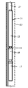
[0021] Fig. 2 shows seal section 19 in a partly schematic cross-sectional
view. Seal
section 19 has a tubular housing 25. An upper connector 27 secures to the
upper end of
housing 25 and connects seal section 19 to pump intake 15 (Fig. 1) in this
embodiment. A
lower connector 29 secures to the lower end of housing 25 and connects housing
25 to other
components, such as another chamber of seal section 19 or a thrust bearing
unit. The terms
"upper", "lower" and the like are used only for convenience. ESP 11 could be
operated in
orientations other than vertical.
[0022] Upper and lower connectors 27, 29 have bores 31 through which a
rotatable drive
shaft 33 extends. Bearings 35, which are shown schematically, support drive
shaft 33 in
bores 31 but do not seal around drive shaft 33. A seal, normally a mechanical
face type (not
shown) seals the upper end of shaft 33 to retard the entry of well fluid.
[0023] Referring to Fig. 3, which does not show shaft 33 (Fig. 2), an upper
retainer 37,
which sealingly inserts into a larger diameter lower portion of bore 31 in
upper connector 27.
Upper connector 27 may be considered to be a part of upper retainer 37. Upper
retainer 37
has a lower portion or neck 39 that extends downward in housing 25 from the
lower side of
upper connector 27. Neck 39 has an outward facing cylindrical wall 41 relative
to a
longitudinal axis 42 of housing 25. In this example, cylindrical wall 41 has a
smaller outer
-6-
Date Regue/Date Received 2022-08-24
diameter than the upper portion of upper retainer 37, defining a downward
facing shoulder
40. A seal ring 43, which may be an 0-ring, encircles and fits within an
annular groove on
cylindrical wall 41.
[0024] A bag or bladder 45 has a circular upper opening 47 at its upper end
49, which is a
short cylindrical portion of bladder 45. Bladder 45 is a tubular, flexible
member and may be
formed of an elastomeric material. Upper end 49 may have a smaller outer
diameter than the
remaining portions of bladder 45. An upper sleeve 51 inserts closely into
upper opening 47.
Upper sleeve 51 is a rigid member formed of a material such as of a steel
alloy. Upper sleeve
51 bonds within upper opening 47. In this example, an adhesive layer 53, shown
schematically, bonds the inner diameter of upper opening 47 to the outer
diameter of upper
sleeve 51. Adhesive layer 53 may be of a variety of types, including pressure
sensitive tape.
In this example, upper sleeve 51 has an external flange 55 on its lower end,
and the lower end
of adhesive layer 53 terminates at external flange 55.
[0025] Upper sleeve 51 fits closely around upper retainer cylindrical wall
41 and is sealed
to cylindrical wall 41 by seal ring 43. A retaining ring 57, which may be a
split, snap ring,
engages a groove on cylindrical wall 41 below upper sleeve 51 to prevent upper
sleeve 51
from sliding downward off of neck 39. The upper end of upper sleeve 51 abuts
or is closely
spaced to downward facing shoulder 40 at the upper end of upper retainer neck
39. Retaining
ring 57 and downward facing shoulder 40 serve as a fastener to secure upper
sleeve 51 to
upper retainer 37.
[0026] As a backup for adhesive layer 53, an optional clamp 58 extends
around bladder
upper end 49. Clamp 58 may be a metal strap that is crimped to exert a
continuous
compressive force on bladder upper end 49 against upper sleeve 51.
-7-
Date Regue/Date Received 2022-08-24
[0027] A lower retainer 59 has a lower portion that sealingly inserts into
bore 31 of lower
connector 29. Lower connector 29 may be considered to be part of lower
retainer 59. Lower
retainer 59 has a cylindrical upper portion that extends upward passed an
upper side 30 of
lower connector 29. That upper portion has an outward facing cylindrical wall
61 with a seal
ring 63 located in a groove encircling cylindrical wall 61.
[0028] Bladder 45 has a circular lower opening 65 in a lower end 67.
Bladder lower end 67
is cylindrical and may have a larger outer diameter than bladder upper end 49.
A lower sleeve
69 inserts into lower opening 65 and is sealed to the inner diameter of
bladder lower opening
65 by an adhesive layer 71. Lower sleeve 69 may have an external flange 73 on
its upper end
above adhesive layer 71. Lower sleeve 69 closely fits over lower retainer
cylindrical wall 61
and is sealed by seal ring 63. A clamp 75, which may the same type as clamp
58, may clamp
around bladder lower end 67 as a backup for adhesive layer 71. A retaining
ring 77 secures to
an annular groove in lower retainer cylindrical wall 61 above lower sleeve 69.
The lower end
of lower sleeve 69 abuts or is closely spaced to connector upper side 30,
which serves as an
upward facing shoulder to prevent upward movement of lower sleeve 69 on
retainer 59.
Retaining ring 77 prevents upward movement of lower sleeve 69 on lower
retainer 59.
Retaining ring 77 and lower retainer shoulder define a fastener forsecuring
lower sleeve 69 to
lower retainer 59. Upper and lower retaining rings 57, 77 are located within
the interior of
bladder 45.
[0029] Referring also to Fig. 2, a guide tube 79 extends between upper
retainer 37 and
lower retainer 59. The upper end of guide tube 79 slides into the inner
diameter of upper
retainer neck 39. An external upward facing shoulder 80 on guide tube 79 abuts
the lower end
of upper retainer neck 39. Similarly, the lower end of guide tube 79 slides
into the inner
diameter of lower retainer 59. A downward facing shoulder 40 on guide tube 79
abuts the
upper side of lower retainer 59.
-8-
Date Regue/Date Received 2022-08-24
[0030] Shaft 33 extends through guide tube 79 and has a smaller diameter than
the inner
diameter of guide tube 79, creating an annular passage. The annular passage is
in
communication with lubricant in motor 17 (Fig. 1). Ports 81 near the upper end
of guide tube
79 communicate lubricant in motor 17 (Fig. 1) and in guide tube 79 with the
interior of
bladder 45. A port (not shown) in upper connector 27 admits well fluid to the
interior of
housing 25 on the exterior of bladder 45. Bladder 45 expands and contracts in
response to a
pressure difference between the well fluid and the lubricant in motor 17.
[0031] In one method of assembly, a technician positions upper and lower
sleeves 51, 69
around upper and lower retainers 37, 59 and secures them with retaining rings
57, 77. Guide
tube 79 may be installed between upper and lower retainers 37, 59 before or
after installing
upper and lower sleeves 51, 69. Then, the technician slides bladder 45 lower
end 67 and upper
end 49 downward over upper retainer 37. He then and slides bladder lower end
67 downward
over flange 73 around lower sleeve 69. The technician then bonds bladder lower
end 67 to
lower sleeve 69 with adhesive layer 71. Then the technician positions bladder
upper end 49
around upper sleeve 51 and bonds it with adhesive layer 53. The technician
positions the sub
assembly of guide tube 79, sleeves 51, 69, bag 45 and retainers 39, 59 in
housing 25, stabbing
lower retainer 59 into bore 31 in lower connector 29. The technician then
secures upper
connector 27 to housing 25, causing upper retainer 37 to stab into bore 31 of
upper connector
27.
[0032] When ESP 11 is retrieved for repair or replacement, technicians may
easily
disassemble seal section 19 and discard bladder 45 along with upper and lower
sleeves 51, 69
still bonded to bladder 45. A new bladder 45 and new upper and lower sleeves
51, 69 may be
installed in seal section 19. Because bladder 45 is not bonded to upper and
lower retainers 37,
59, upper and lower retainers 37, 59 may be easily re-used. Adhesive layers
53, 71 prevent
leakage into or out of bladder 45 better than if clamps 58, 75 are used
without adhesive
-9-
Date Regue/Date Received 2022-08-24
bonding.
[0033] Figs. 4 and 5 illustrate another embodiment, and some of the
components that are
the same as in Figs. 2 and 3 will not be described again. The components that
are mentioned
and which are the same as in Figs 2 and 3 will have the same reference
numeral, except for a
prefix. Referring to Fig. 4, upper retainer 37 has an upper sleeve 51
sealingly mounted around
it. Unlike the first embodiment, upper sleeve 51 has a lower end that is below
upper retainer
37. A set screw 87 extends through the side wall of upper sleeve 51 into
engagement with an
annular recess 89 extending around the exterior of upper retainer 37. Bladder
upper opening
147 bonds to the outer side of upper sleeve 51 with an adhesive layer 153. Set
screw 87 is
located above bladder upper end 149.
[0034] Referring to Fig. 5, lower retainer 59 has a lower sleeve 93 mounted
around it.
Unlike the first embodiment, lower sleeve 93 has an upper end that is above
the upper side of
lower retainer 59. A set screw 95 extends through the side wall of lower
sleeve 93 into
engagement with an annular recess 97 extending around the exterior of lower
retainer 59.
Bladder lower opening 165 bonds to the outer side of lower sleeve 93 with an
adhesive layer
171. Set screw 95 is located below bladder lower end 167.
[0035] In the second embodiment, in one method, bladder upper opening 147
will be
bonded to upper sleeve 51 before upper sleeve 51 is installed on upper
retainer 37. Also,
bladder lower opening 165 will be bonded to lower sleeve 93 before it is
installed on lower
retainer 59. Then, a technician may insert upper retainer 37 into upper sleeve
51 and secure it
with set screw 87. The technician inserts lower retainer 59 into lower sleeve
93 and
secures it with set screw 95. Both set screws 87, 95 are exterior of the
interior of bladder 145.
Date Regue/Date Received 2022-08-24
[0036] The subassembly comprising bladder 145, guide tube 179, and upper
and lower
retainers 37, 59 may then be lowered into housing 125 until lower retainer 59
stabs into lower
connector 129. Upper connector 127 may be secured into the upper end of
housing 125 with
upper retainer 37 stabbing into bore 133.
[0037] The present disclosure described herein, therefore, is well adapted
to carry out the
objects and attain the ends and advantages mentioned, as well as others
inherent therein.
While two embodiments of the disclosure have been given for purposes of
disclosure,
numerous changes exist in the details of procedures for accomplishing the
desired results.
These and other similar modifications will readily suggest themselves to those
skilled in the
art, and are intended to be encompassed within the scope of the appended
claims.
-11-
Date Regue/Date Received 2022-08-24