Note : Les descriptions sont présentées dans la langue officielle dans laquelle elles ont été soumises.
- 1 -
DESCRIPTION
Title of Invention: WATER HEATING SYSTEM
Technical Field
The present disclosure relates to a water heating
system.
Background Art
In the related art, a water heating system including a
water heat exchanger that heats water by using a refrigerant
is known. In the water heating system, scale may adhere due
to water being heated at the water heat exchanger. An
example of a technique based on the assumption that scale
adheres to a water heat exchanger is a heat pump hot water
supply system disclosed in Patent Literature 1 (Japanese
Unexamined Patent Application Publication No. 2015-17761).
In the heat pump hot water supply system disclosed in
Patent Literature 1, a water heat exchanger is divided into
a high-temperature-side water heat exchanger and a low-
temperature-side water heat exchanger, a hot water output
temperature sensor is provided on a hot water outlet side of
the high-temperature-side water heat exchanger, and a hot
water temperature sensor is provided on an outlet side of
the low-temperature-side water heat exchanger. In addition,
the heat pump hot water supply system includes a control
unit that, when a value detected by the outlet hot water
temperature sensor of the low-temperature-side water heat
exchanger exceeds a set value at the time of a reduction in
performance caused by scale adhesion to the high-
CA 03171710 2022- 9- 14
- 2 -
temperature-side water heat exchanger, performs suppression
control on the hot water outlet temperature to be less than
or equal to a set value, and outputs reduction information
about the hot water output temperature and maintenance
information about the high-temperature-side water heat
exchanger.
Summary of Invention
Technical Problem
However, in Patent Literature 1 above, the adhesion of
scale is limited at the high-temperature-side water heat
exchanger to prevent the spread of scale to the low-
temperature-side water heat exchanger. In this way, in
Patent Literature 1, scale is caused to adhere to the high-
temperature-side water heat exchanger. In this case, the
frequency of cleaning or exchanging the high-temperature-
side water heat exchanger is increased, and costs are
increased.
Solution to Problem
A water heating system according to a first aspect
includes a refrigerant circuit and a water circuit. The
refrigerant circuit has a compressor, and a refrigerant
flows in the refrigerant circuit. Water flows in the water
circuit. The refrigerant circuit and the water circuit share
a water heat exchanger that heats water by using the
refrigerant discharged from the compressor. The water heat
exchanger includes a first heat-exchanging unit. In the
first heat-exchanging unit, the refrigerant and water at a
CA 03171710 2022- 9- 14
- 3 -
water outlet portion exchange heat with each other. The
refrigerant circuit further has a heat radiator. The heat
radiator is disposed between the compressor and the first
heat-exchanging unit, and radiates heat of the refrigerant
discharged from the compressor.
In the water heating system according to the first
aspect, the first heat-exchanging unit at which the
refrigerant and water at the water outlet portion exchange
heat with each other is a portion at which water has a high
temperature in the water heat exchanger. However, in the
water heating system according to the first aspect, the heat
radiator that radiates the heat of the refrigerant is
disposed between the compressor and the first heat-
exchanging unit. Since the heat radiator causes the
refrigerant to radiate the heat before the refrigerant flows
into the first heat-exchanging unit, the temperature of the
refrigerant that flows into the first heat-exchanging unit
can be reduced. Therefore, in the first heat-exchanging
unit, it is possible to suppress an increase in the
temperature of the water at the water outlet portion.
Accordingly, it is possible to prevent scale from adhering
to the water heat exchanger.
A water heating system according to a second aspect is
the water heating system according to the first aspect, in
which the heat radiator includes a heat storage material
that radiates heat of the refrigerant.
The water heating system according to the second aspect
CA 03171710 2022- 9- 14
- 4 -
makes it possible to prevent scale from adhering to the
water heat exchanger and to store the heat of the
refrigerant in the heat storage material.
A water heating system according to a third aspect is
the water heating system according to the first aspect or
the second aspect in which the heat radiator includes a
heat-radiating device that radiates heat of the refrigerant
to atmosphere.
The water heating system according to the third aspect
makes it possible to prevent scale from adhering to the
water heat exchanger and to radiate the heat of the
refrigerant to the atmosphere.
A water heating system according to a fourth aspect is
the water heating system according to any one of the first
aspect to the third aspect in which the heat radiator is
configured to radiate heat of the refrigerant to water that
flows on an upstream side of the water outlet portion.
In the water heating system according to the fourth
aspect, the temperature of the water that flows on the
upstream side of the water outlet portion is lower than the
temperature of water that flows in the water outlet portion.
Here, the heat radiator is capable of heating the low-
temperature water on the upstream side by the refrigerant
before water is heated at the first heat-exchanging unit.
Therefore, it is possible to prevent scale from adhering to
the water heat exchanger and to efficiently heat the water.
A water heating system according to a fifth aspect is
CA 03171710 2022- 9- 14
- 5 -
the water heating system according to the fourth aspect, in
which the water heat exchanger further includes a second
heat-exchanging unit that exchanges heat with the
refrigerant on an upstream side of the first heat-exchanging
unit in the water circuit. The heat radiator includes the
second heat-exchanging unit.
In the water heating system according to the fifth
aspect, the temperature of water that flows in the second
heat-exchanging unit is lower than the temperature of water
that flows in the first heat-exchanging unit. Here, the heat
radiator is capable of heating the low-temperature water in
the second heat-exchanging unit by using the refrigerant
before water is heated at the first heat-exchanging unit.
Therefore, it is possible to realize a water heating system
that prevents scale from adhering to the water heat
exchanger and that is capable of efficiently heating water.
A water heating system according to a sixth aspect is
the water heating system according to the fifth aspect, in
which the refrigerant circuit further has a bypass pipe in
which the refrigerant bypasses one of the first heat-
exchanging unit and the second heat-exchanging unit when a
defrosting operation is performed.
In the water heating system according to the sixth
aspect, due to the refrigerant bypassing the first heat-
exchanging unit at the time of the defrosting operation, it
is possible to use the heat amount that has been stored at
the second heat-exchanging unit having a high-temperature
CA 03171710 2022- 9- 14
- 6 -
refrigerant, as a result of which it is possible to reduce a
defrosting operation time. Due to the refrigerant bypassing
the second heat-exchanging unit at the time of the
defrosting operation, it is possible to use the heat amount
that has been stored by heat exchange with the high-
temperature refrigerant, as a result of which it is possible
to cause water to reach a predetermined temperature at an
early stage at the time of a heating operation.
A water heating system according to a seventh aspect is
the water heating system according to any one of the first
aspect to the sixth aspect, in which, in at least a part of
the water heat exchanger, a water flow direction and a
refrigerant flow direction are in a counter-flow
relationship.
The water heating system according to the seventh
aspect is capable of improving heat exchange efficiency by
causing the refrigerant and water to flow in a counter-flow
relationship.
A water heating system according to an eighth aspect is
the water heating system according to any one of the first
aspect to the seventh aspect, in which at least one of the
refrigerant circuit and the water circuit is configured to
allow circulation also in a corresponding one of a reverse
refrigerant flow direction and a reverse water flow
direction.
In the water heating system according to the eighth
aspect, even if scale adheres, the scale can be dispersed
CA 03171710 2022- 9- 14
- 7 -
due to circulation in the reverse direction, as a result of
which the life of the water heat exchanger can be increased.
A water heating system according to a ninth aspect is
the water heating system according to any one of the first
aspect to the eighth aspect, in which the water circuit
further has a take-out portion that takes out water from
between a water inlet portion and the water outlet portion
of the water heat exchanger.
The water heating system according to the ninth aspect
makes it possible to take out high-temperature water at the
water outlet portion and intermediate-temperature water
between the water outlet portion and the water inlet
portion, the high-temperature water and the intermediate-
temperature water being heated by the refrigerant in the
water heat exchanger.
Brief Description of Drawings
[Fig. 1] Fig. 1 is a schematic structural view of a
water heating system according to a first embodiment.
[Fig. 2] Fig. 2 is a schematic structural view of a
water heating system according to a second embodiment.
[Fig. 3] Fig. 3 is a schematic structural view of a
water heating system according to a third embodiment.
[Fig. 4] Fig. 4 is a schematic structural view of a
water heating system according to a modification of the
third embodiment.
[Fig. 5] Fig. 5 is a schematic structural view of a
water heating system according to a fourth embodiment.
CA 03171710 2022- 9- 14
- 8 -
[Fig. 6] Fig. 6 is a schematic structural view of the
water heating system according to the fourth embodiment.
[Fig. 7] Fig. 7 is a schematic structural view of a
water heating system according to a fifth embodiment.
[Fig. 8] Fig. 8 is a schematic structural view of the
water heating system according to the fifth embodiment.
[Fig. 9] Fig. 9 is a schematic structural view of a
water heating system according to a modification of the
fourth embodiment and the fifth embodiment.
[Fig. 10] Fig. 10 is a schematic structural view of a
water heating system according to a sixth embodiment.
[Fig. 11] Fig. 11 is a schematic structural view of the
water heating system according to the sixth embodiment.
[Fig. 12] Fig. 12 is a schematic structural view of a
water heating system according to a seventh embodiment.
[Fig. 13] Fig. 13 is a schematic structural view of a
water heating system according to an eighth embodiment.
[Fig. 14] Fig. 14 is a schematic structural view of a
water heating system according to a ninth embodiment.
Description of Embodiments
A water heating system according to an embodiment of
the present disclosure is described with reference to the
drawings.
(1) First Embodiment
(1-1) Overall Structure
A water heating system 1 according to an embodiment of
the present disclosure heats water by using a refrigerant.
CA 03171710 2022 9 14
- 9 -
The water heating system 1 of the present embodiment is a
hot water supply system.
As shown in Fig. 1, the water heating system 1 includes
a refrigerant circuit 10 and a water circuit 20. The
refrigerant circuit 10 and the water circuit 20 share a
water heat exchanger 30 that heats water by using the
refrigerant.
(1-2) Detailed Structure
(1-2-1) Refrigerant Circuit
A refrigerant flows in the refrigerant circuit 10. As
the refrigerant, for example, a fluid containing R32 is
sealed in the refrigerant circuit 10.
The refrigerant circuit 10 includes a compressor 11, a
heat radiator 12, a condenser 13, an expansion valve 14, and
an evaporator 15. In the refrigerant circuit 10, the
compressor 11, the heat radiator 12, the condenser 13, the
expansion valve 14, and the evaporator 15 are sequentially
connected to each other by a refrigerant pipe.
The compressor 11 is device that compresses a low-
pressure refrigerant into a high-pressure refrigerant. The
compressor 11 of the present embodiment is a compressor of a
type that is capable of controlling the number of rotations
by an inverter circuit and adjusting the discharge amount of
the refrigerant.
The heat radiator 12 radiates heat of the refrigerant
discharged from the compressor 11. Therefore, the
temperature of the refrigerant that has passed through the
CA 03171710 2022- 9- 14
- 10 -
heat radiator 12 is reduced. The heat radiator 12 is
disposed between a first heat-exchanging unit 35 of the
water heat exchanger 30 (described below) and the compressor
11.
The heat radiator 12 exchanges heat with a heat medium
that differs from water in the water circuit 20. The heat
radiator 12 of the present embodiment includes at least one
of a heat storage material that radiates heat of the
refrigerant and a heat-radiating device that radiates heat
of the refrigerant to the atmosphere. In the heat radiator
12, the heat of the refrigerant is radiated to at least one
of the heat storage material and the atmosphere.
The condenser 13 is a condenser that condenses and
liquefies the refrigerant that flows in the refrigerant
circuit 10 by heat exchange. In the present embodiment, the
condenser 13 includes, for example, a heat transfer tube
through which, in the water heat exchanger 30, the
refrigerant that flows in the refrigerant circuit 10 passes.
In the water heat exchanger 30, heat is exchanged between
the refrigerant that flows in the condenser 13 and water
that flows in the water circuit 20.
The expansion valve 14 is a valve that decompresses and
expands the refrigerant that flows in the refrigerant
circuit 10, and is, for example, an electronic expansion
valve.
The evaporator 15 is an evaporator that evaporates the
refrigerant that flows in the refrigerant circuit 10 by heat
CA 03171710 2022- 9- 14
- 11 -
exchange. The evaporator 15 of the present embodiment is an
outdoor unit where heat is exchanged between outside air and
the refrigerant.
(1-2-2) Water Circuit
Water flows in the water circuit 20. The water circuit
20 includes a circulation pump 21, a heat absorber 22, and a
hot water storage tank 23. In the water circuit, the
circulation pump 21, the heat absorber 22, and the hot water
storage tank 23 are sequentially connected to each other by
a water pipe.
The water circuit 20 is a hot-water-supply hot water
circuit that produces hot water from water. In the water
circuit 20, water or hot water circulates so that hot water
heated at the heat absorber 22 of the water heat exchanger
30 is stored in the hot water storage tank 23.
The circulation pump 21 circulates water. The heat
absorber 22 heats water that flows in the water circuit 20
by heat exchange. In the present embodiment, the heat
absorber 22 includes, for example, a heat transfer tube
through which, in the water heat exchanger 30, water that
flows in the water circuit 20 passes. In the water heat
exchanger 30, heat is exchanged between water that flows in
the heat absorber 22 and the refrigerant that flows in the
refrigerant circuit 10. The hot water storage tank 23 stores
hot water heated at the heat absorber 22.
In order to supply and discharge water in the hot water
storage tank 23, a water supply pipe 24 to the hot water
CA 03171710 2022- 9- 14
- 12 -
storage tank 23 and a hot water discharge pipe 25 from the
hot water storage tank 23 are connected to the water circuit
20.
Note that the water circuit 20 may further include a
scale trap for trapping scale.
(1-2-3) Water Heat Exchanger
In the water heat exchanger 30, the heat radiator 12 of
the refrigerant circuit 10 and the heat absorber 22 of the
water circuit 20 are integrally formed. In the water heat
exchanger 30, heat is exchanged between the refrigerant that
flows in the heat radiator 12 and water that flows in the
heat absorber 22.
The water heat exchanger 30 includes a water inlet
portion 31 and a water outlet portion 32 in the water
circuit 20. The water inlet portion 31 is a portion near an
inlet of the water circuit 20 in the water heat exchanger
30. The water outlet portion 32 is a portion near an outlet
of the water circuit 20 in the water heat exchanger 30.
The water heat exchanger 30 includes a refrigerant
inlet portion 33 and a refrigerant outlet portion 34 in the
refrigerant circuit 10. The refrigerant inlet portion 33 is
a portion near an inlet of the refrigerant circuit 10 in the
water heat exchanger 30. The refrigerant outlet portion 34
is a portion near an outlet of the refrigerant circuit 10 in
the water heat exchanger 30.
In the water heat exchanger 30, a water flow direction
and a refrigerant flow direction are in a counter-flow
CA 03171710 2022- 9- 14
- 13 -
relationship. In Fig. 1, in the water heat exchanger 30, the
refrigerant flow direction is a downward direction and the
water flow direction is an upward direction.
The water heat exchanger 30 includes the first heat-
exchanging unit 35 and a second heat-exchanging unit 36. In
Fig. 1, an upper side of the water heat exchanger 30 is the
first heat-exchanging unit 35, and a lower side of the water
heat exchanger 30 is the second heat-exchanging unit 36.
In the first heat-exchanging unit 35, the refrigerant
and water at the water outlet portion 32 exchange heat with
each other. The first heat-exchanging unit 35 exchanges heat
with the refrigerant on a downstream side of the water
circuit 20 in the water heat exchanger 30. Here, in the
first heat-exchanging unit 35, water at the water outlet
portion 32 and the refrigerant at the refrigerant inlet
portion 33 exchange heat with each other.
The second heat-exchanging unit 36 exchanges heat with
the refrigerant on an upstream side of the first heat-
exchanging unit 35 in the water circuit 20. In the second
heat-exchanging unit 36, the refrigerant and water at the
water inlet portion 31 exchange heat with each other. Here,
in the second heat-exchanging unit 36, water at the water
inlet portion 31 and the refrigerant at the refrigerant
outlet portion 34 exchange heat with each other.
As the water heat exchanger 30, for example, a double-
pipe-type heat exchanger or a plate-type heat exchanger can
be used. The double-pipe-type heat exchanger is a heat
CA 03171710 2022- 9- 14
- 14 -
exchanger including an inner pipe in which a refrigerant
flow path or a water flow path is formed inside, and an
outer pipe that is provided on an outer side of the inner
pipe and in which a water flow path or the refrigerant flow
path is formed between the outer pipe and the inner pipe.
The plate-type heat exchanger is a heat exchanger in which
water flow paths or fluid flow paths are alternately formed
between a plurality of stacked plates.
(1-3) Operation of Water Heating System
Next, an operation of the water heating system 1 is
described.
In the refrigerant circuit 10, the refrigerant
discharged from the compressor 11 flows into the heat
radiator 12. The heat radiator 12 radiates heat of the
refrigerant discharged from the compressor 11. The
refrigerant whose temperature has been reduced due to the
heat being radiated at the heat radiator 12 flows into the
water heat exchanger 30. At the condenser 13 of the water
heat exchanger 30, heat is radiated from water, and the
refrigerant is condensed. After the refrigerant condensed at
the condenser 13 has expanded at the expansion valve 14, the
refrigerant flows into the evaporator 15. The refrigerant
absorbs heat from outside air and evaporates at the
evaporator 15. In the refrigerant circuit 10, the
refrigerant circulates in this way, and a compression
stroke, a condensation stroke, an expansion stroke, and an
evaporation stroke are repeated. Between the compression
CA 03171710 2022- 9- 14
- 15 -
stroke and the condensation stroke, the refrigerant radiates
heat at the heat radiator 12.
In the water circuit 20, water of the hot water storage
tank 23 is supplied to the heat absorber 22 of the water
heat exchanger 30 by the circulation pump 21, and absorbs
heat from the refrigerant and is thus heated. Hot water
produced by heating returns to the hot water storage tank
23, and circulation of the hot water in the water circuit 20
is continued until the heat storage temperature reaches a
predetermined heat storage temperature.
In this way, after the refrigerant compressed to a high
temperature at the compressor 11 has exchanged heat with a
heat medium, other than water, that is heated at the heat
radiator 12, the refrigerant exchanges heat with water at
the water outlet portion 32 of the water heat exchanger 30.
(1-4) Features
The water heating system 1 of the present embodiment
includes a refrigerant circuit 10 and a water circuit 20.
The refrigerant circuit 10 has a compressor 11, and a
refrigerant flows therein. Water flows in the water circuit
20. The refrigerant circuit 10 and the water circuit 20
share the water heat exchanger 30 that heats water by using
the refrigerant discharged from the compressor 11. The water
heat exchanger 30 includes a first heat-exchanging unit 35.
In the first heat-exchanging unit 35, the refrigerant and
water at the water outlet portion 32 exchange heat with each
other. The refrigerant circuit 10 further has a heat
CA 03171710 2022- 9- 14
- 16 -
radiator 12. The heat radiator 12 is disposed between the
compressor 11 and the first heat-exchanging unit 35, and
radiates heat of the refrigerant discharged from the
compressor 11.
In the water heating system 1 of the present
embodiment, the first heat-exchanging unit 35 at which water
at the water outlet portion 32 and the refrigerant exchange
heat with each other is a portion at which water has the
highest temperature in the water circuit 20 at the water
heat exchanger 30. Here, the heat radiator 12 that radiates
heat of the refrigerant is disposed between the compressor
11 and the first heat-exchanging unit 35. Since the heat
radiator 12 radiates heat before the refrigerant flows into
the first heat-exchanging unit 35, the temperature of the
refrigerant that flows into the first heat-exchanging unit
35 can be reduced. Therefore, in the first heat-exchanging
unit 35, it is possible to suppress an increase in the
temperature of water at the water outlet portion 32.
Therefore, it is possible to suppress an increase in the
temperature of a surface of the water outlet portion 32 of
the first heat-exchanging unit 35. Therefore, it is possible
to prevent scale from adhering to the water heat exchanger
30.
In this way, in the water heating system of the present
embodiment, since it is possible to prevent scale from
adhering to the water heat exchanger 30, it is possible to
reduce the frequency of cleaning or exchanging the water
CA 03171710 2022- 9- 14
- 17 -
heat exchanger 30.
In the water heating system 1, the heat radiator 12 may
include a heat storage material that radiates heat of the
refrigerant. In this case, it is possible to prevent scale
from adhering to the water heat exchanger 30 and to store
the heat of the refrigerant in the heat storage material.
The water heating system 1 may include a heat-radiating
device that radiates heat of the refrigerant to the
atmosphere. In this case, it is possible to prevent scale
from adhering to the water heat exchanger 30 and to radiate
the heat of the refrigerant to the atmosphere.
Here, in at least a part of the water heat exchanger
30, the water flow direction and the refrigerant flow
direction are in a counter-flow relationship. By causing the
refrigerant and water to flow in a counter-flow
relationship, it is possible to improve heat exchange
efficiency.
(1-5) Modification of First Embodiment
Although the heat radiator 12 of the first embodiment
above includes at least one of a heat storage material and a
heat-radiating device, the heat radiator 12 is not limited
as long as it exchanges heat with a heat medium that differs
from water in the water circuit 20. In the present
modification, the refrigerant circuit 10 has a plurality of
outdoor units, at least one outdoor unit is used as an
evaporator, and the other outdoor unit is used as the heat
radiator 12.
CA 03171710 2022- 9- 14
- 18 -
(2) Second Embodiment
(2-1) Overall Structure
A water heating system 2 of a second embodiment shown
in Fig. 2 is basically the same as the water heating system
1 of the first embodiment, but differs primarily in a heat
radiator 12. Although the heat radiator 12 of the first
embodiment exchanges heat with a heat medium that differs
from water in the water circuit 20, the heat radiator 12 of
the second embodiment exchanges heat with water in a water
circuit 20. As shown in Fig. 2, in the water heating system
2 of the present embodiment, the heat radiator 12 is
configured to radiate heat of a refrigerant to water that
flows on an upstream side of a water outlet portion 32.
(2-2) Detailed Structure
In the heat radiator 12, a heat medium with which the
refrigerant discharged from a compressor 11 exchanges heat
is water that is heated in a water heat exchanger 30.
Specifically, in a refrigerant pipe in which the refrigerant
discharged from the compressor 11 flows, the heat radiator
12 is disposed on a portion close to a water pipe on an
upstream side of the water heat exchanger 30. Here, a
refrigerant circuit 10 has a first refrigerant pipe 16 that
connects the compressor 11 and the heat radiator 12 to each
other and a second refrigerant pipe 17 that connects the
heat radiator 12 and a refrigerant inlet portion 33 to each
other.
Since the water circuit 20 and the water heat exchanger
CA 03171710 2022- 9- 14
- 19 -
30 are the same as those of the first embodiment, the
description thereof is not repeated.
(2-3) Operation of Water Heating System
In the refrigerant circuit 10, the refrigerant
discharged from the compressor 11 flows into the heat
radiator 12 via the first refrigerant pipe 16. The heat
radiator 12 radiates heat of the refrigerant discharged from
the compressor 11 to water in the water circuit 20. The
refrigerant whose temperature has been reduced due to the
heat being radiated at the heat radiator 12 flows into the
water heat exchanger 30 via the second refrigerant pipe 17.
At a condenser 13 of the water heat exchanger 30, heat is
radiated from water, and the refrigerant is condensed. After
the refrigerant condensed at the condenser 13 has expanded
at an expansion valve 14, the refrigerant flows into an
evaporator 15. At the evaporator 15, heat is absorbed from
outside air, and the refrigerant is evaporated. In the
refrigerant circuit 10, the refrigerant circulates in this
way, and a compression stroke, a condensation stroke, an
expansion stroke, and an evaporation stroke are repeated.
In the water circuit 20, water of a hot water storage
tank 23, before being supplied to a heat absorber 22 of the
water heat exchanger 30 by a circulation pump 21, absorbs
heat from the refrigerant that flows in the heat radiator 12
and is heated. The water that has been heated by the heat
radiator 12 flows into the water heat exchanger 30 and
further absorbs heat from the refrigerant at the heat
CA 03171710 2022- 9- 14
- 20 -
absorber 22, as a result of which the water is heated. Hot
water produced by the heating returns to the hot water
storage tank 23.
In this way, after the refrigerant compressed to a high
temperature at the compressor 11 has exchanged heat with
water that flows on the upstream side of the water outlet
portion 32, the refrigerant exchanges heat with water at the
water outlet portion 32 of the water heat exchanger 30.
(2-4) Features
The water heating system 2 of the present embodiment is
configured to radiate heat of the refrigerant to water that
flows on the upstream side of the water outlet portion 32.
In the water circuit 20 of the water heating system 2,
the temperature of water that flows on the upstream side of
the water outlet portion 32 is lower than the temperature of
water that flows in the water outlet portion 32. Here, the
heat radiator 12 is capable of heating the low-temperature
water on the upstream side by the refrigerant before the
water is heated at the first heat-exchanging unit 35.
Therefore, it is possible to prevent scale from adhering to
the water heat exchanger 30 and to efficiently heat water.
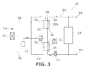
(3) Third Embodiment
(3-1) Overall Structure
A water heating system 3 of a third embodiment shown in
Fig. 3 is basically the same as the water heating system 2
of the second embodiment, but differs primarily in a water
heat exchanger 30 and a heat radiator 12. Although the first
CA 03171710 2022- 9- 14
- 21 -
heat-exchanging unit 35 and the second heat-exchanging unit
36 are disposed at one water heat exchanger 30 in the second
embodiment, they are disposed at different water heat
exchangers in the third embodiment. As shown in Fig. 3, the
water heating system 3 of the present embodiment includes a
water heat exchanger constituted by a first heat-exchanging
unit 35 and a water heat exchanger constituted by a second
heat-exchanging unit 36. The heat radiator 12 includes the
second heat-exchanging unit 36.
(3-2) Detailed Structure
(3-2-1) Refrigerant Circuit
A refrigerant circuit 10 includes a compressor 11, a
first condenser 13a, a second condenser 13b, an expansion
valve 14, and an evaporator 15. In the refrigerant circuit
10, the compressor 11, the first condenser 13a, the second
condenser 13b, the expansion valve 14, and the evaporator 15
are sequentially connected to each other by a refrigerant
pipe. A first refrigerant pipe 16 connects the compressor 11
and the first condenser 13a to each other. A second
refrigerant pipe 17 connects the first condenser 13a and the
second condenser 13b to each other. A third refrigerant pipe
18 connects the second condenser 13b and the evaporator 15
to each other.
The first condenser 13a is disposed at the second heat-
exchanging unit 36 of a water heat exchanger 30. At the
first condenser 13a, in the second heat-exchanging unit 36,
heat is exchanged between a refrigerant that flows in the
CA 03171710 2022- 9- 14
- 22 -
first condenser 13a and water that flows in a water circuit
20.
The second condenser 13b is connected in series with
the first condenser 13a. The second condenser 13b is
disposed at the first heat-exchanging unit 35 of the water
heat exchanger 30. At the second condenser 13b, in the first
heat-exchanging unit 35, heat is exchanged between a
refrigerant that flows in the second condenser 13b and water
that flows in the water circuit 20.
The heat radiator 12 of the present embodiment is the
second heat-exchanging unit 36 in the refrigerant circuit
10. Therefore, the heat radiator 12 radiates the heat of the
refrigerant to water that flows in the second heat-
exchanging unit 36.
(3-2-2) Water Circuit
The water circuit 20 includes a circulation pump 21, a
first heat absorber 22a, a second heat absorber 22b, and a
hot water storage tank 23. In the water circuit 20, the
circulation pump 21, the first heat absorber 22a, the second
heat absorber 22b, and the hot water storage tank 23 are
sequentially connected to each other by a water pipe.
The first heat absorber 22a is disposed at the second
heat-exchanging unit 36 of the water heat exchanger 30. At
the first heat absorber 22a, in the second heat-exchanging
unit 36, heat is exchanged with the refrigerant that flows
in the first condenser 13a.
The second heat absorber 22b is connected in series
CA 03171710 2022- 9- 14
- 23 -
with the first heat absorber 22a. The second heat absorber
22b is disposed at the first heat-exchanging unit 35 of the
water heat exchanger 30. At the second heat absorber 22b, in
the first heat-exchanging unit 35 of the water heat
exchanger 30, heat is exchanged between water that flows in
the second heat absorber 22b and water that flows in the
refrigerant circuit 10.
(3-2-3) Water Heat Exchanger
The water heat exchanger 30 is divided into a water
heat exchanger including the first heat-exchanging unit 35
and a water heat exchanger including the second heat-
exchanging unit 36. The first heat-exchanging unit 35 has a
water outlet portion 32 and a refrigerant outlet portion 34.
The water outlet portion 32 corresponds to the second heat
absorber 22b, and the refrigerant outlet portion 34
corresponds to the second condenser 13b. The second heat-
exchanging unit 36 has a water inlet portion 31 and a
refrigerant inlet portion 33. The water inlet portion 31
corresponds to the first heat absorber 22a, and the
refrigerant inlet portion 33 corresponds to the first
condenser 13a.
In the first heat-exchanging unit 35, a water flow
direction and a refrigerant flow direction are in a counter-
flow relationship. In the second heat-exchanging unit 36, a
water flow direction and a refrigerant flow direction are in
a counter-flow relationship. In Fig. 3, the refrigerant flow
direction in the first heat-exchanging unit 35 and the
CA 03171710 2022- 9- 14
- 24 -
refrigerant flow direction in the second heat-exchanging
unit 36 are the same. In Fig. 3, the water flow direction in
the first heat-exchanging unit 35 and the water flow
direction in the second heat-exchanging unit 36 are the
same.
Here, the water heat exchanger 30 is constituted by two
heat exchangers. In the present description, in the water
heat exchanger 30 that is constituted by one or a plurality
of heat exchangers, the water outlet portion 32 is an outlet
vicinity portion including an outlet that is positioned on a
most downstream side of the water circuit 20.
(3-3) Operation of Water Heating System
In the refrigerant circuit 10, the refrigerant
discharged from the compressor 11 flows into the second
heat-exchanging unit 36, serving as the heat radiator 12,
via the first refrigerant pipe 16. At the second heat-
exchanging unit 36, in the first condenser 13a, heat of the
refrigerant discharged from the compressor 11 is radiated to
water in the water circuit 20. The refrigerant whose
temperature has been reduced due to the heat being radiated
at the heat radiator 12 flows into the first heat-exchanging
unit 35 via the second refrigerant pipe 17. At the first
heat-exchanging unit 35, in the second condenser 13b, heat
is radiated to water in the water circuit 20 and the
refrigerant is condensed. After the refrigerant condensed at
the first condenser 13 and the second condenser 13 has
expanded at the expansion valve 14, the refrigerants flow
CA 03171710 2022- 9- 14
- 25 -
into the evaporator 15 via the third refrigerant pipe 18.
In the water circuit 20, water of the hot water storage
tank 23 flows into the second heat-exchanging unit 36 by the
circulation pump 21. At the second heat-exchanging unit 36,
serving as the heat radiator 12, water of the water circuit
20 absorbs heat from the refrigerant and is heated at the
first heat absorber 22a. The water that has been heated at
the heat radiator 12 flows into the first heat-exchanging
unit 35 and further absorbs heat from the refrigerant at the
second heat absorber 22b, as a result of which the water is
heated. Hot water produced by the heating returns to the hot
water storage tank 23.
In this way, after the refrigerant compressed to a high
temperature at the compressor 11 has exchanged heat with
water at the second heat-exchanging unit 36, the refrigerant
exchanges heat with water at the water outlet portion 32 of
the first heat-exchanging unit 35.
(3-4) Features
The water heat exchanger 30 of the water heating system
3 of the present embodiment further includes the second
heat-exchanging unit 36 that exchanges heat with the
refrigerant on an upstream side of the first heat-exchanging
unit 35 in the water circuit 20. The heat radiator 12
includes the second heat-exchanging unit 36.
In the water heating system 3 of the present
embodiment, the temperature of water that flows in the
second heat-exchanging unit 36 is lower than the temperature
CA 03171710 2022- 9- 14
- 26 -
of water that flows in the first heat-exchanging unit 35.
Here, the heat radiator 12 is capable of heating the low-
temperature water at the second heat-exchanging unit 36 by
the refrigerant before the water is heated at the first
heat-exchanging unit 35. Therefore, it is possible to
realize the water heating system 3 that is capable of
preventing scale from adhering to the water heat exchanger
30 and that is capable of efficiently heating water.
(3-5) Modification of Third Embodiment
Although the water heating system 3 of the above-
described embodiment includes two separated water heat
exchangers, a water heating system 3a of the present
modification shown in Fig. 4 includes a first heat-
exchanging unit 35 and a second heat-exchanging unit 36 that
are separated by a refrigerant flow path of one water heat
exchanger 30.
The water heat exchanger 30 includes the first heat-
exchanging unit 35 and the second heat-exchanging unit 36.
In the refrigerant circuit 10 inside the water heat
exchanger 30, a refrigerant flow path that passes through
the first heat-exchanging unit 35 and a refrigerant flow
path that passes through the second heat-exchanging unit 36
are separated from each other. The second refrigerant pipe
17 of the refrigerant circuit 10 causes a refrigerant that
has flowed out from the first heat-exchanging unit 35 to
flow into the second heat-exchanging unit 36 of the water
heat exchanger 30 that is shared with the first heat-
CA 03171710 2022- 9- 14
- 27 -
exchanging unit 35.
Plate-type heat exchangers are suitably used as water
heat exchangers in the water heating system 3 of the above-
described embodiment in which the first heat-exchanging unit
35 and the second heat-exchanging unit 36 are separated into
a plurality of water heat exchangers. On the other hand, a
double-pipe-type heat exchanger is suitably used as a water
heat exchanger in the water heating system 3a of the present
modification in which one water heat exchanger is divided
into the first heat-exchanging unit 35 and the second heat-
exchanging unit 36 by the refrigerant flow path.
(4) Fourth Embodiment
(4-1) Overall Structure
A water heating system 4 of a fourth embodiment shown
in Figs. 5 and 6 is basically the same as the water heating
system 3 of the third embodiment, but differs primarily in a
refrigerant circuit 10. The water heating system 4 of the
present embodiment is capable of performing a defrosting
operation for defrosting. The refrigerant circuit 10 further
has a bypass pipe 19 in which a refrigerant bypasses a first
heat-exchanging unit 35 when a defrosting operation is
performed.
(4-2) Detailed Structure
The refrigerant circuit 10 further has the bypass pipe
19, a first valve Bl, and a second valve B2.
The bypass pipe 19 is connected to a second refrigerant
pipe 17 that connects a first condenser 13a and a second
CA 03171710 2022- 9- 14
- 28 -
condenser 13b to each other and to a third refrigerant pipe
18 that connects the second condenser 13b and an expansion
valve 14 to each other. When a defrosting operation is
performed, the refrigerant that flows in the third
refrigerant pipe 18 bypasses the first heat-exchanging unit
35 and flows in the second refrigerant pipe 17 due to the
bypass pipe 19.
The first valve B1 is provided at the second
refrigerant pipe 17. The second valve B2 is provided at the
bypass pipe 19. The first valve B1 and the second valve B2
are on-off valves.
Since a water circuit 20 and a water heat exchanger 30
are the same as those of the third embodiment, a description
thereof is not repeated.
(4-3) Operation of Water Heating System
(4-3-1) Heating Operation
Fig. 5 shows flows of the refrigerant and water when a
heating operation of the present embodiment is performed. A
heating operation of the water heating system 4 is described
with reference to Fig. 5.
At the time of the heating operation, the first valve
B1 is fully open and the second valve B2 is fully closed. In
the refrigerant circuit 10, the refrigerant discharged from
a compressor 11 passes through a first refrigerant pipe 16
and flows into a second heat-exchanging unit 36, serving as
a heat radiator 12. At the second heat-exchanging unit 36,
in the first condenser 13a, heat of the refrigerant
CA 03171710 2022- 9- 14
- 29 -
discharged from the compressor 11 is radiated to water in
the water circuit 20. Since the first valve B1 is open, the
refrigerant whose temperature has been reduced due to the
heat being radiated at the heat radiator 12 flows through
the second refrigerant pipe 17 and flows into the first
heat-exchanging unit 35. At the first heat-exchanging unit
35, in the second condenser 13b, heat is radiated to water
in the water circuit 20 and the refrigerant is condensed.
After the refrigerant condensed at the second condenser 13
has passed through the third refrigerant pipe 18 and has
expanded at the expansion valve 14, the refrigerant flows
into an evaporator 15.
In the water circuit 20, water of a hot water storage
tank 23 flows sequentially into the second heat-exchanging
unit 36 and the first heat-exchanging unit 35 by a
circulation pump 21. Water in the water circuit 20 is heated
by the refrigerant at the second heat-exchanging unit 36 and
the first heat-exchanging unit 35. Hot water produced by the
heating returns to the hot water storage tank 23.
(4-3-2) Defrosting Operation
Fig. 6 shows flows of the refrigerant and water when a
defrosting operation of the present embodiment is performed.
In Fig. 6, a water inlet portion 31, a water outlet portion
32, a refrigerant inlet portion 33, and a refrigerant outlet
portion 34 are each provided with a reference sign based on
a direction of flow of the refrigerant and water when a
heating operation is performed (the same as in Fig. 5). A
CA 03171710 2022- 9- 14
- 30 -
defrosting operation of the water heating system 4 is
described with reference to Fig. 6.
When, at the time of the heating operation, frost
formation is detected due to, for example, a reduction in
the temperature of the refrigerant at the evaporator 15, a
defrosting operation that dissolves the frost that has
adhered to the evaporator 15 is performed.
When the defrosting operation is performed, the first
valve B1 is fully closed and the second valve B2 is fully
open. The refrigerant discharged from the compressor 11
flows into a heat exchanger that functions as the evaporator
when a heating operation is performed, radiates heat to
outside air, and is condensed. Although the refrigerant
passes through the third refrigerant pipe 18 after being
15 expanded at the expansion valve 14, since the first valve B1
is closed and the second valve B2 is open, the refrigerant
bypasses the first heat-exchanging unit 35 and passes
through the bypass pipe 19. The refrigerant flows through
the second refrigerant pipe 17 connected to the bypass pipe
19 and flows into the second heat-exchanging unit 36. The
refrigerant passes through a flow path that functions as the
first condenser 13a when a heating operation is performed
and the first refrigerant pipe 16, and is sucked into the
compressor 11.
(4-4) Features
In the water heating system 4 of the present
embodiment, the refrigerant circuit 10 further has a bypass
CA 03171710 2022- 9- 14
- 31 -
pipe 19 in which the refrigerant bypasses the first heat-
exchanging unit 35 when a defrosting operation is performed.
Since, by bypassing the first heat-exchanging unit 35 when a
defrosting operation is performed, it is possible to use the
heat amount that has been stored at the second heat-
exchanging unit 36 that contains a high-temperature
refrigerant, it is possible to reduce a defrosting operation
time.
(5) Fifth Embodiment
(5-1) Overall Structure
A water heating system 5 of a fifth embodiment shown in
Figs. 7 and 8 is basically the same as the water heating
system 3 of the third embodiment, but differs primarily in a
refrigerant circuit 10. The water heating system 5 of the
present embodiment is capable of performing a defrosting
operation. The refrigerant circuit 10 further has a bypass
pipe 19 in which a refrigerant bypasses a second heat-
exchanging unit 36 when a defrosting operation is performed.
(5-2) Detailed Structure
The refrigerant circuit 10 further has the bypass pipe
19, a first valve Bl, and a second valve B2.
The bypass pipe 19 is connected to a first refrigerant
pipe 16 that connects a compressor 11 and a first condenser
13a to each other and to a second refrigerant pipe 17 that
connects the first condenser 13a and a second condenser 13b
to each other. When a defrosting operation is performed, the
refrigerant that flows in the second refrigerant pipe 17
CA 03171710 2022- 9- 14
- 32 -
bypasses the second heat-exchanging unit 36 and flows in the
first refrigerant pipe 16 due to the bypass pipe 19.
The first valve B1 is provided at the second
refrigerant pipe 17. The second valve B2 is provided at the
bypass pipe 19. The first valve B1 and the second valve B2
are on-off valves.
Since a water circuit 20 and a water heat exchanger 30
are the same as those of the third embodiment, a description
thereof is not repeated.
(5-3) Operation of Water Heating System
(5-3-1) Heating Operation
Fig. 7 shows flows of the refrigerant and water when a
heating operation of the present embodiment is performed. A
heating operation of the water heating system 4 is described
with reference to Fig. 7.
At the time of the heating operation, the first valve
B1 is fully open and the second valve B2 is fully closed. In
the refrigerant circuit 10, since the first valve B1 is
open, the refrigerant discharged from the compressor 11
flows through the first refrigerant pipe 16 and flows into
the second heat-exchanging unit 36, serving as a heat
radiator 12. At the second heat-exchanging unit 36, in the
first condenser 13a, heat of the refrigerant discharged from
the compressor 11 is radiated to water in the water circuit
20. The refrigerant whose temperature has been reduced due
to the heat being radiated at the heat radiator 12 flows
through the second refrigerant pipe 17 and flows into the
CA 03171710 2022- 9- 14
- 33 -
first heat-exchanging unit 35. At the first heat-exchanging
unit 35, in the second condenser 13b, heat is radiated to
water in the water circuit 20 and the refrigerant is
condensed. After the refrigerant condensed at the second
condenser 13 has passed through a third refrigerant pipe 18
and has expanded at an expansion valve 14, the refrigerant
flows into an evaporator 15.
In the water circuit 20, water of a hot water storage
tank 23 flows sequentially into the second heat-exchanging
unit 36 and the first heat-exchanging unit 35 by a
circulation pump 21. Water in the water circuit 20 is heated
by the refrigerant at the second heat-exchanging unit 36 and
the first heat-exchanging unit 35. Hot water produced by the
heating returns to the hot water storage tank 23.
(5-3-2) Defrosting Operation
Fig. 8 shows flows of the refrigerant and water when a
defrosting operation of the present embodiment is performed.
In Fig. 8, a water inlet portion 31, a water outlet portion
32, a refrigerant inlet portion 33, and a refrigerant outlet
portion 34 are each provided with a reference sign based on
a direction of flow of the refrigerant and water when a
heating operation is performed (the same as in Fig. 7). A
defrosting operation of the water heating system 5 is
described with reference to Fig. 8.
When the defrosting operation is performed, the first
valve B1 is fully closed and the second valve B2 is fully
open. The refrigerant discharged from the compressor 11
CA 03171710 2022- 9- 14
- 34 -
flows into a heat exchanger that functions as the evaporator
15 when a heating operation is performed, radiates heat to
outside air, and is condensed. After the refrigerant has
expanded at the expansion valve 14, the refrigerant flows
through the third refrigerant pipe 18 and flows into the
first heat-exchanging unit 35. Then, the refrigerant flows
through a flow path that functions as a second condenser 13b
when a heating operation is performed, and flows out from
the first heat-exchanging unit 35. Thereafter, although the
refrigerant passes through the second refrigerant pipe 17,
since the first valve B1 is closed and the second valve B2
is open, the refrigerant bypasses the second heat-exchanging
unit 36 and passes through the bypass pipe 19. The
refrigerant passes through the first refrigerant pipe 16
that is connected to the bypass pipe 19, and is sucked into
the compressor 11.
(5-4) Features
In the water heating system 5 of the present
embodiment, the refrigerant circuit 10 further has a bypass
pipe 19 in which a refrigerant bypasses the second heat-
exchanging unit 36 when a defrosting operation is performed.
Due to the refrigerant bypassing the second heat-exchanging
unit 36 at the time of a defrosting operation, it is
possible to use the heat amount that has been stored by heat
exchange with a high-temperature refrigerant, as a result of
which it is possible to cause water to reach a predetermined
temperature at an early stage at the time of a heating
CA 03171710 2022- 9- 14
- 35 -
operation.
(5-5) Modification of Fourth Embodiment and Fifth
Embodiment
In the fourth embodiment, the refrigerant circuit 10
further has the bypass pipe 19 in which the refrigerant
bypasses the first heat-exchanging unit 35 when a defrosting
operation is performed. In the fifth embodiment, the
refrigerant circuit 10 further has a bypass pipe 19 in which
a refrigerant bypasses the second heat-exchanging unit 36
when a defrosting operation is performed. In the present
modification, as shown in Fig. 9, the refrigerant circuit 10
further has a bypass pipe 19 in which a refrigerant bypasses
the first heat-exchanging unit 35 and the second heat-
exchanging unit 36 when a defrosting operation is performed.
A water heating system of the present modification has
a configuration that is the same as the configuration of the
water heating system of the first embodiment shown in Fig.
1, but differs in that the refrigerant circuit 10 further
has a bypass pipe 19. The bypass pipe 19 of the present
modification is connected to the second refrigerant pipe 17
that connects the heat radiator 12 and the condenser 13 to
each other and to the third refrigerant pipe 18 that
connects the condenser 13 and the expansion valve 14 to each
other.
By closing the second valve B2 that is provided at the
bypass pipe 19 and opening the first valve Bl that is
provided at the second refrigerant pipe 17, it is possible
CA 03171710 2022- 9- 14
- 36 -
to perform a heating operation. By opening the second valve
B2 that is provided at the bypass pipe 19 and closing the
first valve B1 that is provided at the second refrigerant
pipe 17, it is possible to perform a defrosting operation.
(6) Sixth Embodiment
(6-1) Overall Structure
A water heating system 6 of a sixth embodiment shown in
Figs. 10 and 11 is basically the same as the water heating
system 3 of the third embodiment, but differs primarily in a
refrigerant circuit 10 and a water circuit 20. The water
heating system 6 of the present embodiment is configured so
that at least one of the refrigerant circuit 10 and the
water circuit 20 is configured to allow circulation also in
a corresponding one of a reverse refrigerant flow direction
and a reverse water flow direction.
(6-2) Detailed Structure
(6-2-1) Refrigerant Circuit
The refrigerant circuit 10 further has a switching
mechanism 41. The switching mechanism 41 is a flow-path
switching mechanism that switches a flow of a refrigerant in
the refrigerant circuit 10. Here, the switching mechanism 41
is a four-way switching valve. The switching mechanism 41
switches the direction of flow of the refrigerant between a
first direction and a second direction that is a direction
opposite to the first direction.
When the refrigerant is caused to flow in the first
direction shown in Fig. 10, as indicated by a solid line of
CA 03171710 2022- 9- 14
- 37 -
the switching mechanism 41 in Fig. 10, the switching
mechanism 41 causes a first port 41a and a second port 41b
to communicate with each other and causes a third port 41c
and a fourth port 41d to communicate with each other.
Therefore, a compressor 11 and a first condenser 13a are
connected to each other, and a second condenser 13b and an
expansion valve 14 are connected to each other.
When the refrigerant is caused to flow in the second
direction shown in Fig. 11, as indicated by a solid line of
the switching mechanism in Fig. 11, the switching mechanism
41 causes the first port 41a and the third port 41c to
communicate with each other and causes the second port 41b
and the fourth port 41d to communicate with each other.
Therefore, the compressor 11 and the second condenser 13b
are connected to each other, and the first condenser 13a and
the expansion valve 14 are connected to each other.
(6-2-2) Water Circuit
The water circuit 20 further has a switching mechanism
42. The switching mechanism 42 is a flow-path switching
mechanism that switches the flow of water in the water
circuit 20. Here, the switching mechanism 42 is a four-way
switching valve. The switching mechanism 42 switches the
direction of flow of water between a first direction and a
second direction that is a direction opposite to the first
direction.
When the refrigerant is caused to flow in the first
direction shown in Fig. 10, as indicated by a solid line of
CA 03171710 2022- 9- 14
- 38 -
the switching mechanism 42 in Fig. 10, the switching
mechanism 42 causes a first port 42a and a second port 42b
to communicate with each other and causes a third port 42c
and a fourth port 42d to communicate with each other.
Therefore, a water supply port to a water heat exchanger 30
in a hot water tank 23 and a first heat absorber 22a are
connected to each other, and a hot water receiving port from
the water heat exchanger 30 in the hot water tank 23 and a
second heat absorber 22b are connected to each other.
When water is to be caused to flow in the second
direction shown in Fig. 11, as indicated by a solid line of
the switching mechanism in Fig. 11, the switching mechanism
42 causes the first port 42a and the third port 42c to
communicate with each other and causes the second port 42b
and the fourth port 42d to communicate with each other.
Therefore, the water supply port to the water heat exchanger
30 and the second heat absorber 22b are connected to each
other, and the water receiving port from the water heat
exchanger 30 in the hot water tank 23 and the first heat
absorber 22a are connected to each other.
(6-2-3) Water Heat Exchanger
When the water heat exchanger 30 causes the refrigerant
of the refrigerant circuit 10 and water of the water circuit
20 to circulate in a reverse direction by using a
corresponding one of the switching mechanisms 41 and 42, the
first heat-exchanging unit 35 and the second heat-exchanging
unit 36 are reversed.
CA 03171710 2022- 9- 14
- 39 -
When the refrigerant and water circulate in the first
direction shown in Fig. 10, a water heat exchanger on an
upper side in Fig. 10 constitutes the first heat-exchanging
unit 35, and a water heat exchanger on a lower side in Fig.
10 constitutes the second heat-exchanging unit 36. When the
refrigerant and water circulate in the second direction
shown in Fig. 11, a water heat exchanger on a lower side in
Fig. 11 constitutes the first heat-exchanging unit 35, and a
water heat exchanger on an upper side in Fig. 11 constitutes
the second heat-exchanging unit 36.
(6-3) Operation of Water Heating System
The water heating system 6 of the present embodiment is
capable of performing a first heating operation in which the
refrigerant and water flow in the first direction and a
second heating operation in which the refrigerant and water
flow in the second direction. The first heating operation
and the second heating operation can be selected as
appropriate. Here, the first heating operation and the
second heating operation are alternately switched at a
predetermined operation time.
(6-3-1) First Heating Operation
Fig. 10 illustrates flows of the refrigerant and water
in the first direction of the present embodiment. With
reference to Fig. 10, a heating operation of the water
heating system 6 when the refrigerant and water flow in the
first direction is described.
In the refrigerant circuit 10, when the switching
CA 03171710 2022 9 14
- 40 -
mechanism 41 is switched as shown in Fig. 10, the
refrigerant discharged from the compressor 11 flows through
the second port 41a from the first port 41b and flows into
the second heat-exchanging unit 36, serving as a heat
radiator 12. At the second heat-exchanging unit 36, in the
first condenser 13a, heat of the refrigerant discharged from
the compressor 11 is radiated to water in the water circuit
20. The refrigerant whose temperature has been reduced due
to the heat being radiated at the heat radiator 12 flows
into the first heat-exchanging unit 35 via a second
refrigerant pipe 17. At the first heat-exchanging unit 35,
in the second condenser 13b, heat is radiated to water in
the water circuit 20 and the refrigerant is condensed. After
the refrigerant condensed at the second condenser 13b has
passed through the fourth port 41d from the third port 41c
and has expanded at the expansion valve 14, the refrigerant
flows into the evaporator 15.
In the water circuit 20, when the switching mechanism
42 is switched as shown in Fig. 10, water of the hot water
storage tank 23 passes through the second port 42b from the
first port 42a and flows into the second heat-exchanging
unit 36. At the second heat-exchanging unit 36, in the first
heat absorber 22a, water in the water circuit 20 is heated
by the heat radiator 12 due to heat being absorbed from the
refrigerant. The water that has been heated at the heat
radiator 12 flows into the first heat-exchanging unit 35 and
further absorbs heat from the refrigerant at the second heat
CA 03171710 2022- 9- 14
- 41 -
absorber 22b, as a result of which the water is heated. Hot
water produced by the heating returns to the hot water
storage tank 23 via the fourth port 42d from the third port
42c.
(6-3-2) Second Heating Operation
Fig. 11 illustrates flows of the refrigerant and water
in the second direction of the present embodiment. A heating
operation of the water heating system 6 when the refrigerant
and water flow in the second direction is described with
reference to Fig. 11.
When the switching mechanism 42 is switched as shown in
Fig. 11, in the refrigerant circuit 10, the refrigerant
discharged from the compressor 11 flows through the third
port 41c from the first port 41a and flows into the second
heat-exchanging unit 36, serving as the heat radiator 12. At
the second heat-exchanging unit 36, in the second condenser
13b, heat of the refrigerant discharged from the compressor
11 is radiated to water in the water circuit 20. The
refrigerant whose temperature has been reduced due to the
heat being radiated at the heat radiator 12 flows into the
first heat-exchanging unit 35 via a second refrigerant pipe
17. At the first heat-exchanging unit 35, in the first
condenser 13a, heat is radiated to water in the water
circuit 20 and the refrigerant is condensed. After the
refrigerant condensed at the first condenser 13a has passed
through the fourth port 41d from the second port 41b and has
expanded at the expansion valve 14, the refrigerant flows
CA 03171710 2022- 9- 14
- 42 -
into the evaporator 15.
When the switching mechanism 42 is switched as shown in
Fig. 11, in the water circuit 20, water of the hot water
storage tank 23 passes through the third port 42c from the
first port 42a and flows into the second heat-exchanging
unit 36. At the second heat-exchanging unit 36, in the
second heat absorber 22b, water in the water circuit 20 is
heated by the heat radiator 12 due to heat being absorbed
from the refrigerant. The water that has been heated at the
heat radiator 12 flows into the first heat-exchanging unit
35 and further absorbs heat from the refrigerant at the
first heat absorber 22a, as a result of which the water is
heated. Hot water produced by the heating returns to the hot
water storage tank 23 via the fourth port 42d from the
second port 42b.
(6-4) Features
In the water heating system 6 of the present
embodiment, the refrigerant circuit 10 and the water circuit
are configured to allow circulation also in a
20 corresponding one of the reverse refrigerant flow direction
and the reverse water flow direction. Even if scale adheres,
the scale can be dispersed due to the circulation in a
reverse direction, as a result of which the life of the
water heat exchanger 30 can be increased.
(6-5) Modification of Sixth Embodiment
(6-5-1) Modification 1
In the embodiment above, both of the refrigerant
CA 03171710 2022- 9- 14
- 43 -
circuit 10 and the water circuit 20 are configured to allow
circulation also in a corresponding one of the reverse
refrigerant flow direction and the reverse water flow
direction. In the present modification, although the
refrigerant circuit 10 is configured to cause a refrigerant
to also circulate in a reverse direction, the water circuit
20 is configured to cause the water flow direction to be
constant. Alternatively, while the water circuit 20 may be
configured to allow circulation also in the reverse water
flow direction, the refrigerant circuit 10 may be configured
to cause the refrigerant flow direction to be constant.
(6-5-2) Modification 2
Although in the embodiment above, the switching
mechanism 41 of the refrigerant circuit 10 and the switching
mechanism 42 of the water circuit 20 are each a four-way
switching valve, they are not limited thereto. The switching
mechanism 42 of the water circuit 20 of the present
modification is a two-way switching valve or a reverse
circulation pump.
(7) Seventh Embodiment
(7-1) Overall Structure
A water heating system 7 of a seventh embodiment shown
in Fig. 12 is basically the same as the water heating system
3 of the third embodiment, but differs primarily in a water
circuit 20. In the water heating system 7 of the present
embodiment, the water circuit 20 further has a take-out
portion 37 that takes out water from between a water inlet
CA 03171710 2022- 9- 14
- 44 -
portion 31 and a water outlet portion 32 of a water heat
exchanger 30.
(7-2) Detailed Structure
The water circuit 20 further has the take-out portion
37, a third valve B3, a fourth valve B4, and an
intermediate-temperature water tank 23b. The hot water tank
23 of the third embodiment shown in Fig. 3 corresponds to a
high-temperature water tank 23a of the present embodiment
shown in Fig. 12.
The intermediate-temperature water tank 23b stores
water having a temperature that is lower than the
temperature of water that is stored in the high-temperature
water tank 23a.
The take-out portion 37 of the present embodiment is a
pipe that branches off from between a first heat absorber
22a and a second heat absorber 22b and that is connected to
a receiving port of the intermediate-temperature water tank
23b in the water circuit 20.
The intermediate-temperature water tank 23b receives
intermediate-temperature water from the take-out portion 37.
Here, the intermediate-temperature water tank 23b is
connected to a first water pipe 38 that supplies water to
the water heat exchanger 30. Therefore, the water circuit 20
has a first water circuit in the high-temperature water tank
23a and a second water circuit in the intermediate-
temperature water tank 23b. Note that the water circuit 20
may not have a first water pipe 38, and the intermediate-
CA 03171710 2022- 9- 14
- 45 -
temperature water tank 23b may be constituted by a first
water circuit that only receives intermediate-temperature
water.
The third valve B3 is provided at the take-out portion
37. The fourth valve B4 is provided at a water pipe 39 that
connects the second heat absorber 22b and the high-
temperature water tank 23a to each other. The third valve B3
and the fourth valve B4 are on-off valves.
Note that the water circuit 20 may further have a water
pipe (not shown) that sends high-temperature water to
intermediate-temperature water.
Since a refrigerant circuit 10 and the water heat
exchanger 30 are the same as those of the third embodiment,
the description thereof is not repeated.
(7-3) Operation of Water Heating System
First, a heating operation of taking out intermediate-
temperature water and high-temperature water by opening the
third valve B3 and the fourth valve B4 is described.
In the water circuit 20, water at the high-temperature
water tank 23a and water at the intermediate-temperature
water tank 23b flow into a second heat-exchanging unit 36 by
a circulation pump 21. At the second heat-exchanging unit
36, in the first heat absorber 22a, water in the water
circuit 20 is heated by a heat radiator 12 due to heat being
absorbed from a refrigerant.
A part of the water that has been heated at the heat
radiator 12 flows into the first heat-exchanging unit 35 and
CA 03171710 2022- 9- 14
- 46 -
further absorbs heat from the refrigerant at the second heat
absorber 22b, as a result of which the water is heated.
High-temperature water produced by the heating flows into
the high-temperature water tank 23a.
The remaining water that has been heated at the heat
radiator 12 flows as intermediate-temperature water into the
intermediate-temperature water tank 23b via the take-out
portion 37.
In this way, the water heating system 7 of the present
embodiment is capable of performing a heating operation that
takes out intermediate-temperature water and high-
temperature water. The ratio between the production of
intermediate-temperature water and the production of high-
temperature water can be arbitrarily changed by adjusting
the opening degree of the third valve B3 and the opening
degree of the fourth valve B4.
When the third valve B3 is closed and the fourth valve
B4 is opened, a heating operation that takes out only high-
temperature water is possible as in the third embodiment.
When the third valve is opened and the fourth valve is
closed, a heating operation that takes out only
intermediate-temperature water is possible.
(7-4) Features
In the water heating system 7 of the present
embodiment, the water circuit 20 further has a take-out
portion 37 that takes out water from between the water inlet
portion 31 and the water outlet portion 32 of the water heat
CA 03171710 2022- 9- 14
- 47 -
exchanger 30. Therefore, it is possible to take out high-
temperature water at the water outlet portion 32 and
intermediate-temperature water between the water outlet
portion 32 and the water inlet portion 31, the high-
temperature water and the intermediate-temperature water
being heated by the refrigerant in the water heat exchanger
30.
(8) Eighth Embodiment
(8-1) Overall Structure
In the water heating systems 1 to 7 of the first to
seventh embodiments described above, in the water heat
exchanger 30, the water flow direction and the refrigerant
flow direction are in a counter-flow relationship. In a
water heating system 8 of the present embodiment shown in
Fig. 13, in at least a part of a water heat exchanger 30,
the water flow direction and the refrigerant flow direction
are in a parallel-flow relationship.
(8-2) Detailed Structure
A refrigerant circuit 10 of the present embodiment is
basically the same as the refrigerant circuit 10 of the
water heating system 3a shown in Fig. 4, but differs in that
a refrigerant outlet is positioned at one end of the water
heat exchanger 30 (an upper end in Fig. 12).
In a first heat-exchanging unit 35, in Fig. 13, a
refrigerant flows upward and water flows upward. Therefore,
in the first heat-exchanging unit 35, water and the
refrigerant exchange heat in a parallel flow.
CA 03171710 2022- 9- 14
- 48 -
In a second heat-exchanging unit 36, in Fig. 12, the
refrigerant flows downward and water flows upward.
Therefore, in the second heat-exchanging unit 36, water and
the refrigerant exchange heat with each other in a counter-
flow.
In the water heating system 8 of the present
embodiment, in at least a part of the water heat exchanger
30, the water flow direction and the refrigerant flow
direction are in a parallel flow relationship. Here, in a
part of the water heat exchanger 30, the water flow
direction and the refrigerant flow direction are in a
parallel flow relationship. In this way, the water heat
exchanger 30 can be configured so that the water heating
system 8 causes the refrigerant and water to exchange heat
with each other in a counter-flow and/or a parallel flow.
(9) Ninth Embodiment
(9-1) Overall Structure
A water heating system 9 of a ninth embodiment shown in
Fig. 14 includes a plurality of refrigerant circuits 10a and
10b and a plurality of water circuits 20a and 20b. The
refrigerant circuit 10a and the water circuit 20a share a
water heat exchanger 30a. The refrigerant circuit 10b and
the water circuit 20a share a water heat exchanger 30b. The
refrigerant circuit 10b and the water circuit 20b share a
water heat exchanger 30c.
(9-2) Detailed Structure
(9-2-1) Refrigerant Circuit
CA 03171710 2022- 9- 14
- 49 -
The refrigerant circuit 10a shown on an upper side of
Fig. 14 is the same as the refrigerant circuit 10 of the
modification of the third embodiment shown in Fig. 4. To be
specific, in the refrigerant circuit 10, a compressor ha, a
first condenser 13a-1 serving as a heat-radiator 12a, a
second condenser 13a-2, an expansion valve 14a, and an
evaporator 15a are sequentially connected to each other by a
refrigerant pipe.
The refrigerant circuit 10b shown on a lower side in
Fig. 14 includes a compressor 11b, a first condenser 13b-1
serving as a heat radiator 12b, a second condenser 13b-2, an
expansion valve 14b, and an evaporator 15b. In the
refrigerant circuit 10b, the compressor 11b, the first
condenser 13b-1 serving as the heat radiator 12b, the second
condenser 13b-2, the expansion valve 14b, and the evaporator
15b are sequentially connected to each other by a
refrigerant pipe.
(9-2-2) Water Circuit
The water circuit 20a shown on the upper side of Fig.
14 is the same as the water circuit 20 of the third
embodiment shown in Fig. 3. To be specific, in the water
circuit 20a, a circulation pump 21, a first heat absorber
22a-1, a second heat absorber 22a-2, and a hot water storage
tank 23a are sequentially connected to each other by a water
pipe. The hot water storage tank 23a stores high-temperature
water.
The water circuit 20b shown on the lower side of Fig.
CA 03171710 2022- 9- 14
- 50 -
14 is the same as the water circuit 20 of the first
embodiment shown in Fig. 1. To be specific, in the water
circuit 20b, a circulation pump 21, a heat absorber 22b, and
a hot water storage tank 23b are sequentially connected to
each other by a water pipe. The hot water storage tank 23b
stores intermediate-temperature water.
(9-2-3) Water Heat Exchanger
The water heat exchanger 30a on the upper side of Fig.
14 constitutes the first heat-exchanging unit 35 in relation
to the water heat exchanger 30b at the center. When the
water heat exchanger 30a is seen as a single water heat
exchanger, the water heat exchanger 30a includes the first
heat-exchanging unit 35 in which the second condenser 13a-2
and a water outlet portion 32 exchange heat with each other
and the second heat-exchanging unit 36 in which the first
condenser 13a-1 and a water inlet portion 31 exchange heat
with each other.
The water heat exchanger 30b at the center of Fig. 14
constitutes the second heat-exchanging unit 36 in relation
to the water heat exchanger 30a. Further, in relation to the
water heat exchanger 30c on the lower side of Fig. 14, the
water heat exchanger 30b constitutes the second heat-
exchanging unit 36.
The water heat exchanger 30c on the lower side of Fig.
14 constitutes the first heat-exchanging unit 35 in relation
to the water heat exchanger 30b.
(9-3) Operation of Water Heating System
CA 03171710 2022- 9- 14
- 51 -
At the refrigerant circuit 10a, a refrigerant
discharged from the compressor ha flows into the second
heat-exchanging unit 36 of the water heat exchanger 30a,
serving as the heat radiator 12a, via a first refrigerant
pipe 16a. At the second heat-exchanging unit 36 of the water
heat exchanger 30a, in the first condenser 13a-1, serving as
the heat radiator 12a, heat of the refrigerant discharged
from the compressor ha is radiated to water in the water
circuit 20a. The refrigerant whose temperature has been
reduced due to heat being radiated at the heat radiator 12a
flows into the first heat-exchanging unit 35 of the water
heat exchanger 30a via a second refrigerant pipe 17a. At the
first heat-exchanging unit 35, in the second condenser 13a-
2, heat is radiated to water at the water circuit 20a and
the refrigerant is condensed. After the refrigerant
condensed at the first and second condensers 13a has
expanded at the expansion valve 14, the refrigerant flows
into the evaporator 15 via the third refrigerant pipe 18a.
At the refrigerant circuit 10b, the refrigerant
discharged from the compressor llb flows into the water heat
exchanger 30b, serving as the heat radiator 12b, via a first
refrigerant pipe 16b. The water heat exchanger 30b is the
second heat-exchanging unit 36, and, at the first condenser
13b-1 of the water heat exchanger 30b, heat of the
refrigerant discharged from the compressor ha is radiated
to water in the water circuit 20a. The refrigerant whose
temperature has been reduced due to heat being radiated at
CA 03171710 2022- 9- 14
- 52 -
the heat radiator 12b flows into the water heat exchanger
30c via a second refrigerant pipe 17b. The water heat
exchanger 30c is the first heat-exchanging unit 35, and, at
the second condenser 13b-2 of the water heat exchanger 30c,
heat is radiated to water in the water circuit 20b and the
refrigerant is condensed. After the refrigerant that has
been condensed at the first and second condensers 13b has
expanded at the expansion valve 14b, the refrigerant flows
into the evaporator 15b via a third refrigerant pipe 18b.
In the water circuit 20a, water in the hot water
storage tank 23a flows into the water heat exchanger 30b by
a circulation pump 21a. The water heat exchanger 30b is the
second heat-exchanging unit 36, and in the first heat
absorber 22a-1, water in the water circuit 20a is heated by
the heat radiator 12b due to heat being absorbed from the
refrigerant. The water heated at the heat radiator 12b flows
into the water heat exchanger 30a. At the water heat
exchanger 30a, water is heated by further absorbing heat
from the refrigerant at the second heat-exchanging unit 36
and the second heat absorber 22a-2 of the first heat-
exchanging unit 35. The high-temperature water produced by
the heating returns to the hot water storage tank 23.
In the water circuit 20b, water in the hot water
storage tank 23b flows into the second heat-exchanging unit
36 of the water heat exchanger 30c by a circulation pump
21b. At the first heat-exchanging unit 35 of the water heat
exchanger 30c, water in the water circuit 20b is heated by
CA 03171710 2022- 9- 14
- 53 -
absorbing heat from the refrigerant that has radiated heat
at the water heat exchanger 30b, serving as the heat
radiator 12b. The intermediate-temperature water produced by
the heating returns to the hot water storage tank 23.
(9-4) Features
The water heating system 9 of the present embodiment
includes a plurality of evaporators 15. Here, each
evaporator 15 is an outdoor unit. In this way, the water
heating system 9 of the present disclosure can also be
applied to a system including a plurality of outdoor units.
Although embodiments of the present disclosure have
been described above, it is to be understood that various
changes can be made to the forms and details without
departing from the spirit and the scope of the present
disclosure described in the claims.
CA 03171710 2022- 9- 14
- 54 -
Reference Signs List
1, 2, 3, 3a, 4, 5, 6, 6a, 7, 8, 9 water heating system
10, 10a, 10b refrigerant circuit
11 compressor
12 heat radiator
13 condenser
14 expansion valve
evaporator
19 bypass pipe
10 20, 20a, 20b water circuit
21 circulation pump
22 heat absorber
23 tank
30, 30a, 30b water heat exchanger
15 31 water inlet portion
32 water outlet portion
33 refrigerant inlet portion
34 refrigerant outlet portion
35 first heat-exchanging unit
36 second heat-exchanging unit
37 take-out portion
41, 42 switching mechanism
Citation List
Patent Literature
PTL 1: Japanese Unexamined Patent Application
Publication No. 2015-17761
CA 03171710 2022- 9- 14