Note : Les descriptions sont présentées dans la langue officielle dans laquelle elles ont été soumises.
WO 2022/055676
PCT/US2021/046474
TITLE
[0001] BALANCED WELDING OF DISSIMILAR MATERIALS
FIELD
[0002] The field of the present disclosure is related to systems and methods
for resistance spot welding and, more particularly, to such systems and
methods that consistently form an integral Internnetallic Compound (IMC)
between two dissimilar materials.
BACKGROUND
[0003] Resistance spot welding is a process in which metal surface
points
that are in contact with each other are joined (i.e., welded together) by heat
obtained from resistance of an electrical current. In resistance spot welding,
two electrodes concentrate the electrical current into a spot while pressing
the
work pieces together. The work pieces may include metal sheets that, during
the welding process, are held together under pressure exerted by the
electrodes. Forcing the electrical current through the spot will melt the
metal
and form a weld joint (commonly known as a "nugget") at the point of
pressure after solidification. This re-solidified material helps to join the
two
materials together. In certain scenarios, when two different materials are
spot welded together, a thin IMC will form between the materials in lieu of a
weld nugget. This IMC forms due to the differences in thermal and electrical
properties between the materials being joined. Due to the differences in
properties when welding two dissimilar materials together, one material will
tend to melt before the other material and instead of a nugget forming,
particles will diffuse from one material to the other material in a limited
space
to form a strong alloy between the two materials. However, we will refer to
the joint as a "weld" for simplicity and familiarity.
1
CA 03173141 2022- 9- 23
WO 2022/055676
PCT/US2021/046474
[0004]
Resistance spot welding is a popular joining process that is utilized
in a large number of applications, such as automated assembly line
applications, due to its economical and efficiency advantages. Therefore,
resistance spot welding is the most popular joining process in the automotive
industry for assembling automobile bodies. Resistance spot welding is also
widely used in other industries, such as the manufacture of furniture and
domestic equipment, etc. Resistance spot welding is efficient because it can
produce a multitude of spot welds in a short period of time. For example,
resistance spot welding permits welding to occur at localized areas of metal
sheets without excessive heating of the remainder of the metal sheets. When
welding dissimilar materials, however, special care needs to be taken in
regards to the differences in properties between the two dissimilar materials
being welded. Differences in thermal conductivity, melting point, and thermal
expansion can lead to certain combinations of dissimilar materials being
joined
together by an IMC instead of a weld nugget. These differences in material
properties need to be properly balanced while determining the most effective
way to form the IMC in order to ensure what is formed is uniform and
consistent for optimized weld strength.
[0005]
Dependence upon traditional spot welding techniques that are
utilized for welding the same types of material together, such as steel to
steel,
results in the formation of an IMC that is unstable, and therefore unsuitable
for use in industrial applications. Multiple entities have made attempts to
introduce additional processes and materials, such as interlayer inserts, or
fixtures that redirect heating, to counter the imbalance in thermal
properties.
However, these products are not ideal for use in mass production applications
due to their limitations. Previous attempts have also been made to join two
dissimilar materials by either redirecting heat through an additional ground,
or by reducing the buildup of heat in the interface by stopping weld currents
2
CA 03173141 2022- 9- 23
WO 2022/055676
PCT/US2021/046474
at various points to grow a uniform IMC over a staged period of time and
current. However, these attempts are unsatisfactory because they either add
cost to the process or extend cycle times, making them less efficient.
[0006] Advances and improvements to systems and methods for resistance
spot welding are continuously in demand to make the process more cost
efficient. Improvements that utilize traditional weld tooling are viewed as
the
most cost effective solutions when compared to current dissimilar material
fastening applications. Accordingly, there is a need for improved resistance
spot welding systems and methods that consistently form an integral IMC
between two dissimilar materials (in those cases in which an INC is formed).
SUMMARY
[0007] Disclosed are systems and methods for resistance spot
welding
dissimilar materials which overcome at least some of the above described
limitations of the prior art. Disclosed is a resistance spot welding method
for
joining dissimilar materials together using different electrodes that includes
the steps of pressuring the upper and lower work pieces to clamp the work
pieces together with opposed upper and lower weld electrodes of a weld
machine. In a preheating phase, with the work pieces pressured and clamped
together by the weld electrodes, electrical current is provided through the
weld electrodes to the work pieces at a predetermined level and a
predetermined period of time to provide gradual heating of the work pieces.
In a welding phase after the preheating phase, with the work pieces pressured
and clamped together by the weld electrodes, electrical current is provided
through the weld electrodes to the work pieces at a predetermined level higher
than the preheating phase and a predetermined period of time to form an IMC
between the work pieces. The electrical current is continuously provided to
3
CA 03173141 2022- 9- 23
WO 2022/055676
PCT/US2021/046474
the work pieces from the preheating phase through welding phase without
stops.
[0008] Also disclosed is a resistance spot welding method for
joining work
pieces of dissimilar materials together that includes the steps of a
resistance
spot welding method for joining work pieces of dissimilar materials together,
the method comprising the steps of pressuring the work pieces to clamp the
work pieces together with opposed weld electrodes of a weld machine. In a
preheating phase, with the work pieces pressured and clamped together by
the weld electrodes, electrical current is provided through the weld
electrodes
to the work pieces at a predetermined level and a predetermined period of
time to provide gradual heating of the work pieces. In a welding phase after
the preheating phase, with the work pieces pressured and clamped together
by the weld electrodes, electrical current is provided through the weld
electrodes to the work pieces at a predetermined level higher than the
preheating phase and a predetermined period of time to form an IMC between
the work pieces. In a sloping phase between the preheating phase and the
welding phase, with the work pieces pressured and clamped together by the
weld electrodes, electrical current provided to the work pieces gradually
rises
from the predetermined level of the preheating phase to the predetermined
level of the welding phase over a predetermined period of time. From there,
a tempering phase is typically introduced to control the rate of temperature
cooling between the samples and newly generated IMC. Rate of cooling of the
work pieces can be increased after the tempering phase using cooling fluid
flowing in the weld electrodes while the weld electrodes continue to pressure
and clamp the work pieces together for a predetermined period of time with
constant pressure and no electrical current flowing to the work pieces. The
electrical current is continuously provided to the work pieces throughout the
preheating, sloping, welding, and tempering phases without stops.
4
CA 03173141 2022- 9- 23
WO 2022/055676
PCT/US2021/046474
[0009] From the foregoing disclosure and the following more detailed
description of various preferred embodiments, it will be apparent to those
skilled in the art that the present disclosure provides a significant advance
in
the technology of systems and methods for resistive spot welding of
dissimilar materials. Particularly significant in this regard is the potential
the
invention affords for providing an effective system and method that can
reliably utilize traditional weld tooling. Additional features and advantages
of various preferred embodiments will be better understood in view of the
detailed description provided below.
BRIEF DESCRIPTION OF THE DRAWINGS
[0010] The following figures are included to illustrate certain aspects of the
present disclosure, and should not be viewed as exclusive embodiments. The
subject matter disclosed is capable of considerable modifications,
alterations,
combinations, and equivalents in form and function, without departing from
the scope of this disclosure.
[0011] FIG. 1 is a side view of a welding machine during an
exemplary
welding operation, in accordance with some or all of the principles of the
present disclosure.
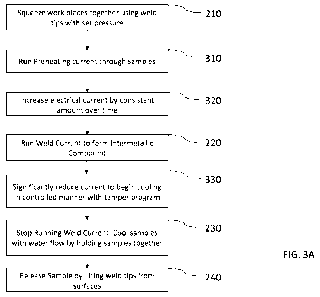
[0012] FIG. 2A is a flow chart of a typical welding process for similar
material
(e.g. steel-to-steel) resistance spot welding. This process features
electrodes
squeezing the work pieces together, and a welding process occurs when a
predetermined current, that can be either constant or varying, runs through
the electrodes and materials for a predetermined period of time. This process
is continuous from beginning to end.
CA 03173141 2022- 9- 23
WO 2022/055676
PCT/US2021/046474
[0013] FIG. 2B is a weld chart of the flow chart identified in
FIG. 2A.
[0014] FIG. 2C. is a Scanning Electron Microscopy (SEM) image of
an IMC
that was formed in a similar manner to the weld and flow charts identified in
FIG. 2A and FIG. 2B. The IMC that forms is inconsistent and filled with cracks
and voids.
[0015] FIG. 2D. is a side view of the of weld electrodes of the
same size
utilized between two materials to demonstrate how welding is traditionally
done between two materials.
[0016] FIG. 3A is a flow chart of a multi-tiered welding process in accordance
with some or all of the principles of the present disclosure. This process
features electrodes squeezing the work pieces together, and a welding process
featuring preheat, slope, weld, and tempering current stages of welding. This
process is continuous from beginning to end.
[0017] FIG. 3B is a weld chart of the flow chart identified in
FIG. 3A.
[0018]
FIG. 3C. is a side view of the different sizes of weld electrodes
utilized between the dissimilar materials to counteract the differences in
thermal conductivity between the work pieces.
[0019] FIG. 4A is a technical drawing of a cross section of welds
produced
by a schedule represented by FIG. 3A to FIG. 3C.
[0020]
FIG. 4B is a microscopic cross section of a weld produced by a
schedule represented by FIG. 3A to FIG. 3C.
6
CA 03173141 2022- 9- 23
WO 2022/055676
PCT/US2021/046474
[0021] FIG. 4C is an SEM image of an IMC that was formed in a
similar
manner to the weld and flow charts identified in FIG. 4A and FIG. 4C. The IMC
that is formed shows significantly fewer cracks and voids compared to FIG.
2C.
[0022] FIG. 5A is a flow chart representing an alternate method for forming
an IMC where the welding process has a plurality of preheating steps to better
control the heating of the work pieces.
[0023] FIG. 5B is a weld chart of the flow chart identified in
FIG. 5A. The
difference in current is shown to be performed in two uninterrupted flows of
current.
[0024] FIG. 5C is a weld chart of the flow chart identified in
FIG. 5A. The
difference in current is shown to be performed in an alternating manner,
similar to a pulse function or alternating current.
[0025] FIG. 6A is a flow chart representing an alternate method for forming
an IMC where the welding process has a plurality of continuous welding steps
to better control the heat balance between the materials.
[0026] FIG. 6B is a weld chart of the flow chart identified in
FIG. 6A. The
difference in current is shown to be performed in two uninterrupted flows of
current.
[0027] FIG. 6C is a weld chart of the flow chart identified in
FIG. 6A. The
difference in current is shown to be performed in an alternating manner,
similar to a pulse function or alternating current.
7
CA 03173141 2022- 9- 23
WO 2022/055676
PCT/US2021/046474
[0028] FIG. 7A is a flow chart representing an alternate method for forming
an IMC that skips the tempering step and goes instantly to cooling by holding
the work pieces with cooled weld tips
[0029] FIG. 7B is a weld chart of the flow chart identified in
FIG. 7A.
[0030] FIG. 8A is a flow chart representing an alternate method for forming
an IMC where the welding process has a plurality of temper steps to better
control the cooling of the work pieces.
[0031]
FIG. 8B is a weld chart of the flow chart identified in FIG. 8A. The
difference in current is shown to be performed in two uninterrupted flows of
current.
[0032]
FIG. 8C is a weld chart of the flow chart identified in FIG. 8A. The
difference in current is shown to be performed in an alternating manner,
similar to a pulse function or alternating current.
[0033]
FIG. 9A is a weld chart that combines the multiple currents and
pulsing functions seen in FIGS. 5C, 6C, and BC into one weld schedule in a
manner that is consistent with a Direct Current weld program.
[0034]
FIG. 9B is a weld chart that takes FIG. 9A and applies a similar
schedule in a manner that is consistent with an Alternating Current Weld
Program.
[0035] FIG. 10A is a flow chart representing an alternate method for forming
an IMC that skips the sloping step between preheating and weld tiers and goes
instantly to the welding tier from the preheat tier.
8
CA 03173141 2022- 9- 23
WO 2022/055676
PCT/US2021/046474
[0036] FIG. 10B is a weld chart of the flow chart identified in
FIG. 7A.
DETAILED DESCRIPTION
[0037]
It will be apparent to those skilled in the art, that is, to those who
have knowledge or experience in this area of technology, that many uses and
design variations are possible for the improved systems and methods
disclosed herein. The following detailed discussion of various alternative and
preferred embodiments will illustrate the general principles of the invention.
Other embodiments suitable for other applications will be apparent to those
skilled in the art given the benefit of this disclosure.
[0038]
Embodiments discussed herein describe a novel process using
current resistance spot welding tooling to join dissimilar materials together.
Some of the embodiments describe differing electrodes that are used to join
the two materials together. These electrodes are selected to counteract the
thermal properties of the different materials by balancing the flow of heat as
current travels between the materials. The electrode for the more conductive
material is significantly larger in diameter than the electrode for the more
resistive material due to the difference in properties such as thermal
conductivity and melting point. These embodiments result in sufficiently
heating the resistive side while avoiding molten expulsion from the conductive
side. In some cases, the heat flow balance may also be achieved by using
electrode contact surfaces or tips of different materials and/or different
contact face geometries, as well as exertion of force or current on either
side
in a single sided manner.
[0039]
Other embodiments disclosed herein describe a welding process
using existing technology in a novel way to consistently form an IMC to
9
CA 03173141 2022- 9- 23
WO 2022/055676
PCT/US2021/046474
thermally join dissimilar materials. Such embodiments include the use of a
complex, multi-tiered weld program containing multiple spot welding
programs combined into one continuous program to distribute heat across the
weld interface to produce a uniform IMC. This multi-tiered weld program helps
to distribute the heat across the interface to form a consistent and integral
IMC. This method not only improves mechanical strength compared to
traditional resistance spot welding, but also has the potential to do so in a
method that is comparably faster than other methods.
[0040] The presently disclosed embodiments provide distributed
heat
between dissimilar materials in a controlled manner. These embodiments
assist in counterbalancing the different thermal properties between the
dissimilar materials, to deliver a satisfactory amount of heat to join them
together. Methods disclosed herein occur while avoiding unfavorable welding
conditions such as expulsion, or an inconsistent IMC, from forming. This
resulting IMC is of optimal thickness, and spreads across the entire weld
surface in a consistent manner. The IMC also contains a significantly reduced
amount of cracking so that it is suitable for use in industrial production.
[0041] In contrast to existing processes in the prior art, these methods will
effectively join two different conductive materials together using existing
weld
tooling, while not requiring a fastener to initially join the pieces together.
These methods also do not require any additional attachments to the weld
tooling to redirect heat, or a cladding material to place in between the
materials. These methods also are continuous, without any stops needed to
reform the molten materials before continuing. The multi-tiered weld
programs described herein occur in one continuous stream of current using
traditional welding machines to effectively join dissimilar materials by
CA 03173141 2022- 9- 23
WO 2022/055676
PCT/US2021/046474
effectively distributing the heat in manner that is congruent with the
different
thermal properties of the materials being joined.
[0042]
Typically, the multi-tiered weld programs will maintain an
uninterrupted flow of current for each tier of the welding process. However,
current is able to change in a manner that is deemed suitable for any stack-
up of dissimilar materials that are being joined. This includes, but is not
limited
to, increasing current in a sloping manner, an alternating pulse function, and
the like for either direct or alternating current welders. This is allowable
as
long as current continues to run in an unbroken manner from start to finish.
These methods are repeatable across multiple stack-ups, and is more effective
than traditional welding, while potentially being faster and more efficient
than
other solutions available.
[0043]
FIG. 1 illustrates an example of a resistance welding machine or
system 100 according to the present subject matter. The welding machine
100 may utilize a variety of robotic or non-robotic welding apparatuses, and
may generally include any type of welder capable to provide the necessary
welding program to the interface of the materials being joined. In some
examples, the welding machine 100 is a servo-driven welder, whereas in other
examples the welding machine 100 is a pneumatic-driven welder; however,
any other type of welding apparatus that are capable of performing similar
techniques may be utilized without deviating from the present disclosure. The
current running through the welder could be Direct Current (DC), Alternating
Current (AC), or any other combination and/or method of applying electric
current to the work pieces.
[0044] As illustrated, the welding machine 100 includes an upper electrode
110 and an opposed lower electrode 120. The upper electrode 110 comes
11
CA 03173141 2022- 9- 23
WO 2022/055676
PCT/US2021/046474
into contact with an upper metal surface 132 of an upper metal work piece as
the lower electrode 120 comes into contact with a lower metal surface 142 of
a lower metal work piece. The illustrated metal work pieces are metal sheets
but can alternatively be of any other suitable type. This process, which
currently being depicted with two sheets, also has the potential to add more
than two sheets to the joining process. Both the upper and lower electrodes
110, 120, are depicted as having a cylindrical shape, with both with differing
uniform radii and shaped faces. FIG. 1 illustrates the electrodes 110, 120
with
flat weld surfaces. However, in other situations or embodiments, the weld
surfaces of the electrodes 110, 120 may have any combination of flat, inward,
or outward features.
[0045] Either the upper electrode 110, and/or the lower electrode 120, may
include any variety of geometries. For example, any combination of the upper
and/or lower electrodes 110, 120 may each be of a certain shape, such that
either the top electrode contact surface 112, or the bottom electrode contact
surface 122, are rounded weld surfaces on ends of the frusto-conical shaped
body and defined by a truncated end radius of the ends of the cylindrical
body.
In most embodiments of dissimilar welding, geometry of the upper electrode
110 is different than the geometry of the lower electrode 120. The upper
electrode 110 and lower electrode 120, may include any variety of shape and
geometries. Regardless of the electrode geometry and weld surface shape,
the electrode contact surfaces 112, 122 may be provided as flat weld surfaces
or with inward or outward protruding curvatures. The electrode surfaces 112,
122 can be smooth or they can have a textured surface comprising of plurality
of male or female oriented features that are selected from a group consisting
of raised or depressed features (teeth, knurls, protrusions, depressions,
ridges, asperities, cross-hatches, parallel or non-parallel lines, star
shapes,
triangles, hexagons, etc. and combinations of the same). This texture helps
12
CA 03173141 2022- 9- 23
WO 2022/055676
PCT/US2021/046474
to break the oxide layer on the surface wherever applicable. For further
information on the textured weld surface, refer to Patent Publication Number
WO/2020/068575, International Application Nurnber PCT/US2019/052094,
which is expressly incorporated herein in its entirety by reference.
[0046] During a typical resistance spot welding operation, the
upper
electrode contact surface 112 of the upper electrode 110 is pressed against
an upper metal part or work piece 130 with a set force to deliver an optimal
pressure, while the lower electrode surface 122 of the lower electrode 120 is
pressed simultaneously with the upper electrode 110 against a lower metal
surface 142 of lower metal part 140 with a set or predetermined force to
deliver the optimal pressure. The electrodes 110, 120 press the work pieces
130, 140 together with the set force at a simultaneous occurrence. As
illustrated, the upper electrode contact surface 112 of the upper electrode
110
is pressed against the upper metal surface 132 of the upper metal part 130
simultaneously with the lower electrode 120 pressing against the lower metal
surface 142 of lower metal part 140. The welding machine 100 then passes
adequate electrical current between the upper and lower electrodes 110, 120
and across the interface of upper and lower metal parts 130, 140 to create an
IMC 151 as an end product to the welding process..
[0047] Weld schedules are integral to forming an INC due to the role they
play in the quality of the joint that is formed. A properly balanced weld
schedule forms a consistent, robust IMC of optimal thickness. Consistent IMCs
of optimal thickness reduce the number of cracks in the alloy that forms
between the dissimilar materials, which reduces the number of points where
internal failure can occur. This results in higher levels of strength being
achievable for welding of dissimilar materials, as well as increased
performance in fatigue, and other forms of cyclical testing. The illustrated
13
CA 03173141 2022- 9- 23
WO 2022/055676
PCT/US2021/046474
weld machine includes a suitable system processor and memory which utilizes
software or programming code to carry out the weld schedules or programs
and other steps disclosed herein below.
[0048] FIG. 2A and FIG. 2B illustrate an example of a typical
prior art
welding program used in traditional steel to steel welding. This process
features electrodes squeezing the work pieces together, and a welding process
occurs when a set amount of current runs through the tips of the electrodes
and the work pieces for a given period of time. This process is continuous
from beginning to end. FIG. 2A is a flowchart of the example showing process
steps 210, 220, 230, and 240, and FIG. 2B is a weld graph of the example.
FIG. 2B presents the weld graph by charting the progression of electrical
current flowing through the work pieces over time from process step 210 to
process step 240. When the traditional welding program is used to join
dissimilar materials, the IMC that forms is inconsistent and erratic in terms
of
size and shape. In certain cases, IMCs may not form and something else
forms in lieu of it. These irregularities lead to excessive defects such as
voids
and cracks and reduce the potential strength of the alloy that holds the
dissimilar materials together. FIG. 2C shows an exemplary SEM image of a
weld that resulted from this traditional welding program, and shows the
shortcomings of using traditional resistance spot welding methods to join
dissimilar materials. This IMC contains many defects, such as voids and
cracks, and may lead to insufficient weld strength. FIG. 2D shows a side view
of similarly sized weld electrodes that are used in traditional welding
between
the steel work pieces.
[0049] FIG. 3A and FIG. 3B illustrate an example of a continuous
weld
program of a preferred embodiment of this disclosure. Various preferred
embodiments disclosed herein will follow the same general flow to properly
14
CA 03173141 2022- 9- 23
WO 2022/055676
PCT/US2021/046474
distribute heat for the proper formation of IMC. Heat is distributed across
several stages of the welding process to form an IMC that is robust and
structurally functional. FIG. 3A is a flowchart of the example having process
steps 210, 310, 320, 220, 330, 230, and 240. FIG. 3B is a weld graph of the
example showing the progression of the electrical current flowing through the
work pieces over time from process step 210 to process step 240. FIG. 3C
shows a side view of the different size weld electrodes that are needed to
counteract the differences in thermal conductivity between the dissimilar work
pieces.
[0050] The upper and lower weld electrodes, 110, 120 squeeze the metal
parts or work pieces 130,140 at contact surfaces 112, 122, together at a set
or predetermined pressure for a predetermined period of time 210. This
pressing of the weld electrode contact surfaces 112, 122 enables the upper
and lower electrodes 110, 120 to break the outer oxide layers of their
respective material surfaces 132, 142, should they exist. The upper electrode
110 creates openings in the oxide of the upper metal part 130 to facilitate a
more effective flow of current, while sustaining tip life by preventing the
electrode surface 112 from sticking to the upper metal part 130 being joined.
The lower electrode 120 creates openings in the oxide (should an oxide layer
exist) of the lower metal part 140 to facilitate a more effective flow of
current.
This approach has the potential to be extended to join more than two sheets
of dissimilar materials.
[0051] With the examples of aluminum and steel as the dissimilar materials,
the weld program utilizes a preheating program 310 to uniformly heat the
area between the upper metal parts 130 and lower metal parts 140. The
electrical current is then sloped up gradually, 320, to melt the coating on
the
steel and to facilitate a phase change from a Body Centered Cubic phase to a
CA 03173141 2022- 9- 23
WO 2022/055676
PCT/US2021/046474
Face Centered Cubic phase. It is noted that while the exemplary slope is
constant to provide a straight angled line, any other suitable rise can
alternatively be used such as, but not limited to, a concave curve, a convex
curve, steps, and the like. This sloping step can be manipulated to different
periods of current and time to better correlate with the resistivity,
weldability,
and thickness of the materials being joined. It is also noted that the sloping
phase between the preheating and welding tiers can also be eliminated if
desired. After this phase change, iron ions will diffuse into the aluminum to
facilitate the creation of the IMC. In the case of welding aluminum and steel,
the aluminum could be 5xxx, 6x)oc, 7xxx, 8xxx or any other alloy of aluminum
in different tempers and thicknesses and may be uncoated or have different
types of surface coatings. Similarly, the steel may be coated or uncoated in
different thicknesses and could have different material strengths (such as but
not limited to low carbon steel, medium strength steels, high strength steels,
hot stamped boron steel, stainless steel, etc.). Other dissimilar material
combinations (besides aluminum and steel) could also be joined by this
approach. Different materials can be joined if they interact in a similar
method
to aluminum and steel when placed under electrical current and pressure. The
changes in phases and crystal structure will depend on the dissimilar
materials
being joined. A variety of suitable times and electrical currents can be used,
and the current progression is not tied to the current values used in the
preheating or welding phases.
[0052] During the creation of the IMC, the electrical current of
the sloping
phase 320, will turn to a continuous predetermined current 220, and weld the
dissimilar materials together to form a thin, consistent INC. A variety of
suitable electrical currents and weld times can be used herein.
16
CA 03173141 2022- 9- 23
WO 2022/055676
PCT/US2021/046474
[0053] After the IMC has been formed, cool down of the metal parts 130,
140 begins. A tempering phase 330 is performed across the weld interface
with the weld electrodes 110, 120. The tempering of the metal parts 130,
140 is performed at a comparably lower electrical current than the welding
phase or stage, and allows for the temperature to gradually drop. This gradual
drop allows for a controlled material transition throughout the material that
melts initially due to the lower melting point to solidify into a region
cooling in
a controlled manner to limit the thermal stress on the IMC. This limitation on
thermal stress reduces cracking in the IMC, resulting in a reduction of
propagation points for failure.
[0054] At the end of the tempering phase or stage when the weld program
has finished running electrical current across the metal parts 130, 140, the
electrodes 110, 120 keep the metal parts 130, 140 held together for a defined
or predetermined period of time 230. Water or any other cooling agent will
continue to flow through the electrodes 110, 120 during this hold time to cool
both the metal parts 130, 140 and the electrodes 110, 120. Once the metal
parts 130, 140 are held for a set or predetermined period of time, the upper
and lower weld electrode surfaces 112, 122 release the sample with the fully
formed IMC, 151, at time 240, signaling the end of the welding process.
[0055] FIGS. 4A to 4C illustrate the cross-sectional view of a
joint after a
successful weld process is performed as described above with regard to FIGS.
3A and 3B. An IMC has formed between the dissimilar materials, successfully
welding them together. The more conductive material melted and reformed
in the region where current travelled on the top side of the IMC. FIG. 4A
gives
a technical drawing of the cross section produced herein. With the example
of the upper metal part 130 being aluminum and the lower metal part 140
being steel, this is obtained after melting and re-solidifying the aluminum at
17
CA 03173141 2022- 9- 23
WO 2022/055676
PCT/US2021/046474
region 150 as a solidified deposit that sits on top of IMC 151. The steel that
is used as lower metal part 130 transitions from a Body Centered Cubic (BCC)
phase to a Face Centered Cubic (FCC) phase, and then back to a BCC phase
upon cooling. The changes in the crystal structure will depend on the
materials being joined. The upper and lower electrode surfaces 112, 122 may
have a specified hardness and contour that are designed for a particular
welding application. FIG. 46 gives microscopic view of the cross section
produced herein. FIG. 4C gives an SEM image of a weld resulting from the
above disclosed method, and shows how utilizing a complex, multi-tiered
welding program can fix the problems created with traditional welding to give
a robust, functional IMC. This results in high amounts of strength for
dissimilar
welding as well as increased performance in fatigue and other forms of
cyclical
testing.
[0056] The weld electrodes 110, 120 preferably each have a contact surface
112, 122 that is oriented so that current flow in the work pieces 130, 140
facilitates Peltier Effect. The Peltier Effect is a thermoelectric effect that
takes
place when an electric current is put through two contacting conductive, but
dissimilar, materials. Due to this effect, one material will give heat to the
other material to balance the gap in chemical potential. As such, current flow
can be aligned in a certain direction in order to facilitate the Peltier
Effect.
While the process can also work in an orientation that is not aligned
according
to the Peltier Effect, it is important to note that utilizing the Peltier
Effect will
allow for a significantly increased level of consistency compared to not doing
so.
[0057] The contact surface 112, 122 of the weld electrode 110, 120 that is
contacting a more conductive one of the dissimilar materials of the work
pieces
130, 140 preferably has an equivalent ratio of diameter to the contact surface
18
CA 03173141 2022- 9- 23
WO 2022/055676
PCT/US2021/046474
112, 122 of the weld electrode 110, 120 contacting a less conductive one of
the dissimilar materials of the work pieces 130, 140 to counteract a gap in
thermal conductivity and thermal expansion between the dissimilar materials.
The contact surface 112, 122 that is chosen to be used on the more conductive
side must be at least the equivalent ratio of the diameter to the contact
surface
112, 122 applied to the less conductive material so that the gap in thermal
conductivity and thermal expansion between dissimilar materials can be
properly counteracted. In some cases, the heat flow balance may also be
achieved by using weld electrodes 110, 120 of different materials and/or
different contact face geometries.
[0058] Certain complexities inherent in the materials discussed herein, and
the IC that joins them together, will occasionally require a higher level of
program variance to facilitate proper bonding. Some factors that will impact
the complexity of the welding procedure are (but not limited to) surface
condition of the material (oxide scale, debris, contaminants, etc.), grades
and
thickness of materials being joined, geometry of materials being joined,
presence of intermediate layer between the materials (adhesive, sealer, etc.),
and number of sheets being joined. There could be several other factors that
will have an impact on the weld schedule. The program variance manifests
itself by introducing additional variations of electrical current to the multi-
tiered welding schedule. These variations, which may add or subtract welding
tiers, are disclosed in FIGS. 5-10. The process disclosed herein is not
limited
to the following figures. FIGS. 5-10 are further examples of the process being
disclosed. Weld programs may contain a variety of current levels that change
in different amounts over time. Actual programs may vary between the
figures discussed herein.
19
CA 03173141 2022- 9- 23
WO 2022/055676
PCT/US2021/046474
[0059] FIGS. 5A to 5C represent a weld process modified from the
weld
process of FIGS. 3A and 3B, wherein the welding process goes through
multiple levels of preheating phases or steps 310, 510, before sloping to the
weld phase or step 220. Multiple preheating tiers can be used for a higher
level of control over the dissimilar materials in situations where the
materials
can be sensitive to changes in thermal loads. Levels of preheating can either
increase or decrease to meet the demands of the material being joined, as
long as there is no stoppage of current, and the final preheating step
progresses by sloping current into the weld step. While the example shown
has two preheating steps 310, 510, it is noted that any other suitable
plurality
of preheating steps can alternatively be utilized if desired. FIG. 5A is a
flowchart of the example, while FIG. 5B is a weld graph of the example having
process steps 210, 310, 510, 320, 220, 330, 230, and 240. FIG. 5B presents
the weld graph by charting the progression of the electrical current flowing
through the weld materials over time from process step 210 to process step
240. The number of levels of preheating may depend on the type of phase
changes that take place and the associated diffusion rates required to form
the INC (in cases where it is formed). The varying tiers of preheating
currents
can be in any number of patterns, such as two uninterrupted preheat currents
as seen in FIG. 5B, or in alternating/pulsing manner, as seen in FIG. 5C.
There
could be some additional benefits of preheating that are dependent on the
metal parts 130, 140 being welded.
[0060] FIGS. 6A to 6C represent a weld process modified from the weld
process of FIGS. 3A and 36 wherein the weld process goes through multiple
levels of welding, 220, 610, before cooling down. Multiple levels of welding
can be utilized to maintain a higher level of control over the types and
concentrations of phases that are being created to make up the IMC. Levels
of welding can either increase or decrease to meet the demands of the
CA 03173141 2022- 9- 23
WO 2022/055676
PCT/US2021/046474
material being joined, as long as there is no stoppage of current, and the
final
welding step progresses into the cooling phase. While the present example
shown has two welding steps 220, 610, it is noted that any other suitable
plurality of welding steps can alternatively be utilized if desired. FIG. 6A
is a
flowchart of the example having process steps 210, 310, 320, 220, 610, 330,
230, and 240. FIG. 6B is a weld graph of the example. FIG. 6B presents the
weld graph by charting the progression of the electrical current flowing
through the metal parts 130, 140 over time from process step 210 to process
step 240. The varying tiers of welding currents can be in any number of
patterns, such as two uninterrupted weld currents as seen in FIG. 6B, or in
alternating/pulsing manner, as seen in FIG. 6C.
[0061] FIGS. 7A and 7B represent a weld process modified from the
weld
process of FIGS. 3A and 3B wherein the weld process bypasses any tempering
phase to go straight to the weld surfaces holding the welded materials without
current running through them to cool down the joined materials. Certain
material combinations may not need the tempering phase to facilitate proper
formation of the IMC. This can result in significant cost savings by way of a
reduced process time. FIG. 7A is a flowchart of the example having process
steps 210, 310, 320, 220, 230, and 240. FIG. 7B is a weld graph of the
example having process steps 210, 310, 320, 220, 230, and 240. FIG. 7B
presents the weld graph by charting the progression of the current flowing
through the metal parts 130, 140 over time from process step 210 to process
step 240.
[0062] FIGS. 8A to 8C represent a weld process modified from the
weld
process of FIGS. 3A and 3B wherein the weld process goes through multiple
levels of tempering, 810, before stopping the flow of current. Multiple levels
of tempering can either increase or decrease in either time or electrical
current
21
CA 03173141 2022- 9- 23
WO 2022/055676
PCT/US2021/046474
to further control the rate of cooling of materials to meet the demands of the
material being joined, as long as there is no stoppage of electrical current.
The process will still conclude by utilizing the pressure from the electrode
surfaces 112, 122 to hold the metal parts 130, 140 together for a specified
amount of time. While the present example shown has two tempering steps
330, 810, it is noted that any other suitable plurality of tempering steps can
alternatively be utilized if desired. FIG. 8A is a flowchart of the example
having
process steps 210, 310, 320, 220, 330, 810, 230, and 240. FIG. 8B is a weld
graph of the example. FIG. 8B presents the weld graph by charting the
progression of the electrical current flowing through the metal parts 130, 140
over time from process step 210 to process step 240. The varying tiers of
tempering currents can be in any number of patterns, such as two consistent
tempering currents as seen in FIG. 86, or in alternating/pulsing manner, as
seen in FIG. 8C.
[0063] FIGS. 9A and 96 take the pulsing currents seen in FIGS. 5C, 6C, and
8C and combined them into one pulsating weld program. FIG. 9A shows this
method in a weld schedule consistent with Direct Current (DC). FIG. 9B shows
this method in a weld schedule consistent with Alternating Current (AC).
[0064] FIGS. 10A and 10B represent a weld process modified from the weld
process of FIGS. 3A and 3B wherein the weld process bypasses any sloping
phase between the preheating and welding tiers to go straight to the welding
tier for the formation of the IMC. Certain material combinations may not need
the sloping phase to facilitate proper formation of the IMC. This can result
in
significant cost savings by way of a reduced process time. FIG. 10A is a
flowchart of the example having process steps 210, 310, 1020, 330, 230, and
240. FIG. 10B is a weld graph of the example having process steps 210, 310,
1020, 330, 230, and 240. FIG. 106 presents the weld graph by charting the
22
CA 03173141 2022- 9- 23
WO 2022/055676
PCT/US2021/046474
progression of the current flowing through the metal parts 130, 140 over time
from process step 210 to process step 240.
[0065]
While the figures are examples of successful programs for welding
dissimilar materials, the invention disclosed herein is not limited to only
the
figures given above. Any quantity and combination of steps can be used, as
long as the weld program is a continuous, multi-tiered process. The electrical
current provided to the work pieces 130, 140 does not need to be contained
to a constant current level and can fluctuate in either a pulsing or sloping
method as long as electric current continually runs through the work pieces
130, 140.
[0066] Any of the features or attributes of the above described embodiments
and variations can be used in combination with any of the other features and
attributes of the above described embodiments and variations as desired.
[0067]
The presently disclosed embodiments provide considerable
efficiencies to welding operations, such as cost and time savings.
For
example, the ability to successfully join dissimilar materials without the use
of
a fastener saves money in most of the applications it is used. The simple, but
novel task of removing a fastener from every single joint will give the entity
that applies this process an advantage by removing the cost and weight of
every single fastener that would traditionally join dissimilar materials
together. The lack of a fastener, as well as the ability to use traditional
weld
tooling, and line layouts, gives significant savings over time. This solution
also
saves a significant amount of time compared to other welding solutions by
keeping a constant flow of energy running through the interface. This allows
for a higher amount of energy to be delivered in a shorter time span as we do
not have the intermittent stops in delivering current.
23
CA 03173141 2022- 9- 23
WO 2022/055676
PCT/US2021/046474
[0068] Therefore, the disclosed systems and methods are well adapted to
attain the ends and advantages mentioned as well as those that are inherent
therein. The particular embodiments disclosed above are illustrative only, as
the teachings of the present disclosure may be modified and practiced in
different but equivalent manners apparent to those skilled in the art having
the benefit of the teachings herein. Furthermore, no limitations are intended
to the details of construction or design herein shown, other than as described
in the claims below. It is therefore evident that the particular illustrative
embodiments disclosed above may be altered, combined, or modified and all
such variations are considered within the scope of the present disclosure. The
systems and methods illustratively disclosed herein may suitably be practiced
in the absence of any element that is not specifically disclosed herein and/or
any optional element disclosed herein. While compositions and methods are
described in terms of "comprising," "containing," or "including" various
components or steps, the compositions and methods can also "consist
essentially of" or "consist of" the various components and steps. All numbers
and ranges disclosed above may vary by some amount. Whenever a
numerical range with a lower limit and an upper limit is disclosed, any number
and any included range falling within the range is specifically disclosed. In
particular, every range of values (of the form, "from about a to about b," or,
equivalently, 'from approximately a to b," or, equivalently, "from
approximately a-b") disclosed herein is to be understood to set forth every
number and range encompassed within the broader range of values. Also, the
terms in the claims have their plain, ordinary meaning unless otherwise
explicitly and clearly defined by the patentee. Moreover, the indefinite
articles
"a" or "an," as used in the claims, are defined herein to mean one or more
than one of the elements that it introduces. If there is any conflict in the
usages of a word or term in this specification and one or more patent or other
24
CA 03173141 2022- 9- 23
WO 2022/055676
PCT/US2021/046474
documents that may be incorporated herein by reference, the definitions that
are consistent with this specification should be adopted.
[0069] As used herein, the phrase "at least one of" preceding a
series of
items, with the terms "and" or "or" to separate any of the items, modifies the
list as a whole, rather than each member of the list (i.e., each item). The
phrase "at least one of" allows a meaning that includes at least one of any
one
of the items, and/or at least one of any combination of the items, and/or at
least one of each of the items. By way of example, the phrases "at least one
of A, B, and C" or "at least one of A, B, or C" each refer to only A, only B,
or
only C; any combination of A, B, and C; and/or at least one of each of A, B,
and C.
CA 03173141 2022- 9- 23