Note : Les descriptions sont présentées dans la langue officielle dans laquelle elles ont été soumises.
WO 2022/049373
PCT/GB2021/052256
- 1 -
A System Comprising a Non-Combustible Aerosol Provision Device
Technical Field
The present invention relates to a system comprising a non-combustible aerosol
provision device; a non-combustible aerosol provision device; a package; and a
control
method of a non-combustible aerosol provision device.
Background
Product packages can be provided with an electromagnetically interrogatable
data
storage, such as an RFID tag, which can contain information relating to the
product
package. An RFID reader can be used to interrogate the RFID tag by
transmitting a
radio frequency signal which is received at the antenna or inductive coil
within the tag.
The RFID tag then returns a signal to the RFID reader containing the
information
relating to the product package.
Summary
In accordance with some embodiments described herein, in a first aspect there
is
provided a system comprising a non-combustible aerosol provision device for
use with
a consumable, the system comprising: one or more controllers; and an
identifier reader
configured to read an identifier associated with one or more consumables,
wherein the
one or more controllers arc configured to record the number of readings of the
identifier and perform an action in response to the recorded number of
readings
reaching a predetermined value.
In accordance with some embodiments described herein, in a second aspect there
is
provided a package for consumables for use with a non-combustible aerosol
provision
device, the package comprising an electromagnetically interrogatable data
storage
storing an identifier, wherein the identifier identifies the package and
includes data
regarding the number of consumables contained within the package.
In accordance with some embodiments described herein, in a third aspect there
is
provided a control method of a non-combustible aerosol provision device for
use with a
consumable, the method comprising: performing readings of an identifier
associated
with one or more consumables; recording the number of readings; and performing
an
action in response to the number of readings reaching a predetermined value.
CA 03174370 2022- 9- 30
WO 2022/049373
PCT/GB2021/052256
- 2 -
Brief Description of Drawings
Embodiments of the invention will now be described, by way of example only,
with
reference to accompanying drawings, in which:
Figure 1 is a perspective illustration of a system comprising a non-
combustible aerosol
provision device, together with a package of consumables;
Figure 2 is a block diagram showing the configurations of the non-combustible
aerosol
provision device and the package shown in Figure 1;
Figure 3 is a block diagram showing a detailed configuration of the non-
combustible
aerosol provision device shown in Figure 2;
/0 Figure 4 is a block diagram showing a detailed configuration of a user
terminal for use
in the system shown in Figure 1;
Figure 5 is a perspective illustration of a non-combustible aerosol provision
device;
Figure 6 illustrates the device of Figure 5 with the outer cover removed;
Figure 7 is a side view of the device of Figure 5 in partial cross-section;
Figure 8 is an exploded view of the device of Figure 5, with [he ouLer cover
omiaed;
Figure 9A is a cross sectional view of a portion of the device of Figure 5;
Figure 9B is a close-up illustration of a region of the device of Figure 9A;
and
Figure 10 is a flow chart showing a control method of a non-combustible
aerosol
provision device for use with a consumable.
Detailed Description
According to the present disclosure, a "non-combustible" aerosol provision
system is
one where a constituent aerosol-generating material of the aerosol provision
system (or
component thereof) is not combusted or burned in order to facilitate delivery
of at least
one substance to a user.
In some embodiments, the delivery system is a non-combustible aerosol
provision
system, such as a powered non-combustible aerosol provision system.
so In some embodiments, the non-combustible aerosol provision system is an
electronic
cigarette, also known as a vaping device or electronic nicotine delivery
system (END),
although it is noted that the presence of nicotine in the aerosol-generating
material is
not a requirement.
CA 03174370 2022- 9- 30
WO 2022/049373
PCT/GB2021/052256
- 3 -
In some embodiments, the non-combustible aerosol provision system is an
aerosol-
generating material heating system, also known as a heat-not-burn system. An
example of such a system is a tobacco heating system.
In some embodiments, the non-combustible aerosol provision system is a hybrid
system to generate aerosol using a combination of aerosol-generating
materials, one or
a plurality of which may be heated. Each of the aerosol-generating materials
may be,
for example, in the form of a solid, liquid or gel and may or may not contain
nicotine.
In some embodiments, the hybrid system comprises a liquid or gel aerosol-
generating
io material and a solid aerosol-generating material. The solid aerosol-
generating material
may comprise, for example, tobacco or a non-tobacco product.
Typically, the non-combustible aerosol provision system may comprise a non-
combustible aerosol provision device and a consumable for use with the non-
combustible aerosol provision device.
In some embodiments, the disclosure relates to consumables comprising aerosol-
generating material and configured to be used with non-combustible aerosol
provision
devices. These consumables are sometimes referred to as articles throughout
the
disclosure. Consumables may be provided in a package.
In some embodiments, the non-combustible aerosol provision system, such as a
non-
combustible aerosol provision device thereof, may comprise a power source and
a
controller. The power source may, for example, be an electric power source or
an
exothermic power source. In some embodiments, the exothermic power source
comprises a carbon substrate which may be energised so as to distribute power
in the
form of heat to an aerosol-generating material or to a heat transfer material
in
proximity to the exothermic power source.
so In some embodiments, the non-combustible aerosol provision system may
comprise an
area for receiving the consumable, an aerosol generator, an aerosol generation
area, a
housing, a mouthpiece, a filter and/or an aerosol-modifying agent.
In some embodiments, the consumable for use with the non-combustible aerosol
provision device may comprise aerosol-generating material, an aerosol-
generating
material storage area, an aerosol-generating material transfer component, an
aerosol
CA 03174370 2022- 9- 30
WO 2022/049373
PCT/GB2021/052256
- 4 -
generator, an aerosol generation area, a housing, a wrapper, a filter, a
mouthpiece,
and/or an aerosol-modifying agent.
In some embodiments, the substance to be delivered may be an aerosol-
generating
material or a material that is not intended to be aerosolised. As appropriate,
either
material may comprise one or more active constituents, one or more flavours,
one or
more aerosol-former materials, and/or one or more other functional materials.
An aerosol generator is an apparatus configured to cause aerosol to be
generated from
io the aerosol-generating material. In some embodiments, the aerosol
generator is a
heater configured to subject the aerosol-generating material to heat energy,
so as to
release one or more volatiles from the aerosol-generating material to form an
aerosol.
In some embodiments, the aerosol generator is configured to cause an aerosol
to be
generated from the aerosol-generating material without heating. For example,
the
aerosol generaLor may be configured lo subject Lhe aerosol-generating material
lo one
or more of vibration, increased pressure, or electrostatic energy.
Aerosol-generating material is a material that is capable of generating
aerosol, for
example when heated, irradiated or energized in any other way. Aerosol-
generating
material may, for example, be in the form of a solid, liquid or gel which may
or may not
contain an active substance and/or flavourants. In some embodiments, the
aerosol-
generating material may comprise an "amorphous solid", which may alternatively
be
referred to as a "monolithic solid" (i.e. non-fibrous). In some embodiments,
the
amorphous solid may be a dried gel. The amorphous solid is a solid material
that may
retain some fluid, such as liquid, within it. In some embodiments, the aerosol-
generating material may for example comprise from about 50wt%, 6owt% or 70wt%
of
amorphous solid, to about 90wt%, 95wt% or mowt% of amorphous solid.
The aerosol-generating material may comprise one or more active substances
and/or
so flavours, one or more aerosol-former materials, and optionally one or
more other
functional material.
The aerosol-former material may comprise one or more constituents capable of
forming
an aerosol. In some embodiments, the aerosol-former material may comprise one
or
more of glycerine, glycerol, propylene glycol, diethylene glycol, triethylene
glycol,
tetraethylene glycol, 1,3-butylene glycol, erythritol, meso-Erythritol, ethyl
vanillate,
CA 03174370 2022- 9- 30
WO 2022/049373
PCT/GB2021/052256
- 5 -
ethyl laurate, a diethyl suberate, triethyl citrate, triacetin, a diacetin
mixture, benzyl
benzoate, benzyl phenyl acetate, tributyrin, lauryl acetate, lauric acid,
myristic acid, and
propylene carbonate.
The one or more other functional materials may comprise one or more of pH
regulators, colouring agents, preservatives, binders, fillers, stabilizers,
and/or
antioxidants.
The material may be present on or in a support, to form a substrate. The
support may,
for example, be or comprise paper, card, paperboard, cardboard, reconstituted
material, a plastics material, a ceramic material, a composite material,
glass, a metal, or
a metal alloy. In some embodiments, the support comprises a susceptor. In some
embodiments, the susceptor is embedded within the material. In some
alternative
embodiments, the susceptor is on one or either side of the material.
An aerosol-modifying agent is a substance, typically located downstream of the
aerosol
generation area, that is configured to modify the aerosol generated, for
example by
changing the taste, flavour, acidity or another characteristic of the aerosol.
The aerosol-
modifying agent may be provided in an aerosol-modifying agent release
component,
that is operable to selectively release the aerosol-modifying agent.
The aerosol-modifying agent may, for example, be an additive or a sorbent. The
aerosol-modifying agent may, for example, comprise one or more of a
flavourant, a
colourant, water, and a carbon adsorbent. The aerosol-modifying agent may, for
example, be a solid, a liquid, or a gel. The aerosol-modifying agent may be in
powder,
thread or granule form. The aerosol-modifying agent may be free from
filtration
material.
A susceptor is a material that is heatable by penetration with a varying
magnetic field,
so such as an alternating magnetic field. The susceptor may be an
electrically-conductive
material, so that penetration thereof with a varying magnetic field causes
induction
heating of the heating material. The heating material may be magnetic
material, so that
penetration thereof with a varying magnetic field causes magnetic hysteresis
heating of
the heating material. The susceptor may be both electrically-conductive and
magnetic,
so that the susceptor is heatable by both heating mechanisms. The device that
is
CA 03174370 2022- 9- 30
WO 2022/049373
PCT/GB2021/052256
- 6 -
configured to generate the varying magnetic field is referred to as a magnetic
field
generator, herein.
Induction heating is a process in which an electrically-conductive object is
heated by
penetrating the object with a varying magnetic field. The process is described
by
Faraday's law of induction and Ohm's law. An induction heater may comprise an
electromagnet and a device for passing a varying electrical current, such as
an
alternating current, through the electromagnet. When the electromagnet and the
object to be heated are suitably relatively positioned so that the resultant
varying
io magnetic field produced by the electromagnet penetrates the object, one
or more eddy
currents are generated inside the object. The object has a resistance to the
flow of
electrical currents. Therefore, when such eddy currents are generated in the
object,
their flow against the electrical resistance of the object causes the object
to be heated.
This process is called Joule, ohmic, or resistive heating. An object that is
capable of
being inductively heated is known as a susceptor.
In one embodiment, the susceptor is in the form of a closed circuit. It has
been found
that, when the susceptor is in the form of a closed circuit, magnetic coupling
between
the susceptor and the electromagnet in use is enhanced, which results in
greater or
improved Joule heating.
Magnetic hysteresis heating is a process in which an object made of a magnetic
material
is heated by penetrating the object with a varying magnetic field. A magnetic
material
can be considered to comprise many atomic-scale magnets, or magnetic dipoles.
When
a magnetic field penetrates such material, the magnetic dipoles align with the
magnetic
field. Therefore, when a varying magnetic field, such as an alternating
magnetic field,
for example as produced by an electromagnet, penetrates the magnetic material,
the
orientation of the magnetic dipoles changes with the varying applied magnetic
field.
Such magnetic dipole reorientation causes heat to be generated in the magnetic
so material.
When an object is both electrically-conductive and magnetic, penetrating the
object
with a varying magnetic field can cause both Joule heating and magnetic
hysteresis
heating in the object. Moreover, the use of magnetic material can strengthen
the
magnetic field, which can intensify the Joule heating.
CA 03174370 2022- 9- 30
WO 2022/049373
PCT/GB2021/052256
- 7 -
In each of the above processes, as heat is generated inside the object itself,
rather than
by an external heat source by heat conduction, a rapid temperature rise in the
object
and more uniform heat distribution can be achieved, particularly through
selection of
suitable object material and geometry, and suitable varying magnetic field
magnitude
and orientation relative to the object. Moreover, as induction heating and
magnetic
hysteresis heating do not require a physical connection to be provided between
the
source of the varying magnetic field and the object, design freedom and
control over the
heating profile may be greater, and cost may be lower.
Articles, for instance those in the shape of rods, are often named according
to the
product length: "regular" (typically in the range 68 ¨ 75 mm, e.g. from about
68 mm to
about 72 mm), "short" or "mini" (68 mm or less), "king size" (typically in the
range 75 ¨
91 mm, e.g. from about 79 mm to about 88 mm), "long" or "super-king"
(typically in the
range 91 ¨ 105 mm, e.g. from about 94 mm to about 101 mm) and "ultra-long"
(typically in the range from about 110 mm to aboUL 121 mm).
They are also named according to the product circumference: "regular" (about
23 ¨ 25
mm), "wide" (greater than 25 mm), "slim" (about 22 - 23 mm), "demi-slim"
(about 19
- 22 mm), "super-slim" (about 16 ¨ 19 mm), and "micro-slim" (less than about
16 mm).
Accordingly, an article in a king-size, super-slim format will, for example,
have a length
of about 83 mm and a circumference of about 17 mm.
Each format may be produced with mouthpieces of different lengths. The
mouthpiece
length will be from about 30 mm to 50 mm. A tipping paper connects the
mouthpiece
to the aerosol generating material and will usually have a greater length than
the
mouthpiece, for example from 3 to 10 mm longer, such that the tipping paper
covers
the mouthpiece and overlaps the aerosol generating material, for instance in
the form
of a rod of substrate material, to connect the mouthpiece to the rod.
Articles and their aerosol generating materials and mouthpieces described
herein can
be made in, but are not limited to, any of the above formats.
The terms 'upstream' and 'downstream' used herein are relative terms defined
in
relation to the direction of mainstream aerosol drawn though an article or
device in
use.
CA 03174370 2022- 9- 30
WO 2022/049373
PCT/GB2021/052256
- 8 -
The filamentary tow material described herein can comprise cellulose acetate
fibre tow.
The filamentary tow can also be formed using other materials used to form
fibres, such
as polyvinyl alcohol (PVOH), polylactic acid (PLA), polycaprolactone (PCL),
poly(1-4
butanediol succinate) (PBS), poly(butylene adipate-co-terephthalate)(PBAT),
starch
based materials, cotton, aliphatic polyester materials and polysaccharide
polymers or a
combination thereof. The filamentary tow may be plasticised with a suitable
plasticiser
for the tow, such as triacetin where the material is cellulose acetate tow, or
the tow may
be non-plasticised. The tow can have any suitable specification, such as
fibres having a
io cross section which is 'Y' shaped, 'X' shaped or '0' shaped. The fibres
of the tow may
have filamentary denier values between 2.5 and 15 denier per filament, for
example
between 8.0 and 11.0 denier per filament and total denier values of 5,000 to
50,000,
for example between 10,000 and 40,4300. The cross section of the fibres may
have an
isoperimetric ratio L2/A of 25 or less, preferably 20 or less, and more
preferably 15 or
less, where L is the length of the perimeter of the cross section and A is the
area of the
cross section. Such fibres have a relatively low surface area for a given
value of denier
per filament, which improves delivery of aerosol to the consumer.
As used herein, the term "tobacco material" refers to any material comprising
tobacco
or derivatives or substitutes thereof. The term "tobacco material" may include
one or
more of tobacco, tobacco derivatives, expanded tobacco, reconstituted tobacco
or
tobacco substitutes. The tobacco material may comprise one or more of ground
tobacco, tobacco fibre, cut tobacco, extruded tobacco, tobacco stem, tobacco
lamina,
reconstituted tobacco and/or tobacco extract.
In some embodiments, the substance to be delivered comprises an active
substance.
The active substance as used herein may be a physiologically active material,
which is a
material intended to achieve or enhance a physiological response. The active
substance
so may for example be selected from nutraceuticals, nootropics,
psychoactives. The active
substance may be naturally occurring or synthetically obtained. The active
substance
may comprise for example nicotine, caffeine, taurine, theine, vitamins such as
B6 or
B12 or C, melatonin, cannabinoids, or constituents, derivatives, or
combinations
thereof. The active substance may comprise one or more constituents,
derivatives or
extracts of tobacco or another botanical.
CA 03174370 2022- 9- 30
WO 2022/049373
PCT/GB2021/052256
- 9 -
In some embodiments, the active substance comprises nicotine. In some
embodiments,
the active substance comprises caffeine, melatonin or vitamin B12.
As noted herein, the active substance may comprise or be derived from one or
more
botanicals or constituents, derivatives or extracts thereof. As used herein,
the term
"botanical" includes any material derived from plants including, but not
limited to,
extracts, leaves, bark, fibres, stems, roots, seeds, flowers, fruits, pollen,
husk, shells or
the like. Alternatively, the material may comprise an active compound
naturally
existing in a botanical, obtained synthetically. The material may be in the
form of
liquid, gas, solid, powder, dust, crushed particles, granules, pellets,
shreds, strips,
sheets, or the like. Example botanicals are tobacco, eucalyptus, star anise,
hemp, cocoa,
cannabis, fennel, lemongrass, peppermint, spearmint, rooibos, chamomile, flax,
ginger,
ginkgo biloba, hazel, hibiscus, laurel, licorice (liquorice), matcha, mate,
orange skin,
papaya, rose, sage, tea such as green tea or black tea, thyme, clove,
cinnamon, coffee,
aniseed (anise), basil, bay leaves, cardamom, coriander, cumin, nuLmeg,
oregano,
paprika, rosemary, saffron, lavender, lemon peel, mint, juniper, elderflower,
vanilla,
wintergreen, beefsteak plant, curcuma, turmeric, sandalwood, cilantro,
bergamot,
orange blossom, myrtle, cassis, valerian, pimento, mace, damien, marjoram,
olive,
lemon balm, lemon basil, chive, carvi, verbena, tarragon, geranium, mulberry,
ginseng,
theanine, theacrine, maca, ashwagandha, damiana, guarana, chlorophyll, baobab
or
any combination thereof. The mint may be chosen from the following mint
varieties:
Mentha Arventis, Mentha c.v.,Mentha niliaca, Mentha piperita, Mentha piperita
citrata
c.v.,Mentha piperita c.v, Mentha spicata crispa, Mentha cardifolia, Memtha
longifolia,
Mentha suaveolens variegata, Mentha pulegium, Mentha spicata c.v. and Mentha
suaveolens.
In some embodiments, the active substance comprises or is derived from one or
more
botanicals or constituents, derivatives or extracts thereof and the botanical
is tobacco.
so In some embodiments, the active substance comprises or derived from one
or more
botanicals or constituents, derivatives or extracts thereof and the botanical
is selected
from eucalyptus, star anise, cocoa and hemp.
In some embodiments, the active substance comprises or derived from one or
more
botanicals or constituents, derivatives or extracts thereof and the botanical
is selected
from rooibos and fennel.
CA 03174370 2022- 9- 30
WO 2022/049373
PCT/GB2021/052256
- 10 -
In some embodiments, the substance to be delivered comprises a flavour.
As used herein, the terms "flavour" and "flavourant" refer to materials which,
where
local regulations permit, may be used to create a desired taste, aroma or
other
somatosensorial sensation in a product for adult consumers. They may include
naturally occurring flavour materials, botanicals, extracts of botanicals,
synthetically
obtained materials, or combinations thereof (e.g., tobacco, cannabis, licorice
(liquorice), hydrangea, eugenolõTapanese white bark magnolia leaf, chamomile,
fenugreek, clove, maple, matcha, menthol, Japanese mint, aniseed (anise),
cinnamon,
turmeric, Indian spices, Asian spices, herb, wintergreen, cherry, berry, red
berry,
cranberry, peach, apple, orange, mango, clementine, lemon, lime, tropical
fruit, papaya,
rhubarb, grape, durian, dragon fruit, cucumber, blueberry, mulberry, citrus
fruits,
Drambuie, bourbon, scotch, whiskey, gin, tequila, rum, spearmint, peppermint,
lavender, aloe vera, cardamom, celery, cascarilla, nuttneg, sandalwood,
bergamot,
geranium, khat, naswar, betel, shisha, pine, honey essence, rose oil, vanilla,
lemon oil,
orange oil, orange blossom, cherry blossom, cassia, caraway, cognac, jasmine,
ylang-
ylang, sage, fennel, wasabi, piment, ginger, coriander, coffee, hemp, a mint
oil from any
species of the genus Mentha, eucalyptus, star anise, cocoa, lemongrass,
rooibos, flax,
ginkgo biloba, hazel, hibiscus, laurel, mate, orange skin, rose, tea such as
green tea or
black tea, thyme, juniper, elderflower, basil, bay leaves, cumin, oregano,
paprika,
rosemary, saffron, lemon peel, mint, beefsteak plant, curcuma, cilantro,
myrtle, cassis,
valerian, pimento, mace, damien, marjoram, olive, lemon balm, lemon basil,
chive,
carvi, verbena, tarragon, limonene, thymol, camphene), flavour enhancers,
bitterness
receptor site blockers, sensorial receptor site activators or stimulators,
sugars and/or
sugar substitutes (e.g., sucralose, acesulfame potassium, aspartame,
saccharine,
cyclamates, lactose, sucrose, glucose, fructose, sorbitol, or mannitol), and
other
additives such as charcoal, chlorophyll, minerals, botanicals, or breath
freshening
agents. They may be imitation, synthetic or natural ingredients or blends
thereof. They
so may be in any suitable form, for example, liquid such as an oil, solid
such as a powder,
or gas.
In some embodiments, the flavour comprises menthol, spearmint and/or
peppermint.
In some embodiments, the flavour comprises flavour components of cucumber,
blueberry, citrus fruits and/or redberry. In some embodiments, the flavour
comprises
eugenol. In some embodiments, the flavour comprises flavour components
extracted
CA 03174370 2022- 9- 30
WO 2022/049373
PCT/GB2021/052256
- 11 -
from tobacco. In some embodiments, the flavour comprises flavour components
extracted from cannabis.
In some embodiments, the flavour may comprise a sensate, which is intended to
achieve a somatosensorial sensation which are usually chemically induced and
perceived by the stimulation of the fifth cranial nerve (trigeminal nerve), in
addition to
or in place of aroma or taste nerves, and these may include agents providing
heating,
cooling, tingling, numbing effect. A suitable heat effect agent may be, but is
not limited
to, vanillyl ethyl ether and a suitable cooling agent may be, but not limited
to
/o eucolyptol, WS-3.
In the figures described herein, like reference numerals are used to
illustrate equivalent
features, articles or components.
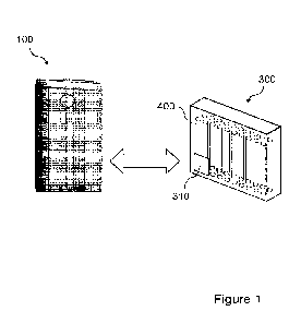
Figure 1 shows a system comprising a non-combustible aerosol provision device,
together with a package of consumables provided for use with the system. In
broad
outline, the non-combustible aerosol provision device loo may be used to heat
a
replaceable article comprising an aerosol generating medium, for instance one
of the
consumables 400 described herein, to generate an aerosol or other inhalable
medium
which is inhaled by a user of the device 100. The device loo and consumable
400
together form a non-combustible aerosol provision system.
As shown in Figure 1, the package 300 includes an electromagnetically
interrogatable
data storage 310. The electromagnetically interrogatable data storage 310
stores data
relating to the consumables 400 and/or the package 300. Such data is referred
to
herein as an identifier. In the present example, the electromagnetically
interrogatable
data storage 310 stores data identifying the package. The identifier stored in
the
electromagnetically interrogatable data storage 310 can be read by an
identifier reader,
such as an identifier reader of the device 100. This operation will be
described in more
3o detail below. In some examples, the identifier also includes data
regarding the number
of consumables contained within the package as manufactured.
The electromagnetically interrogatable data storage 310 may be located on the
outside
of the package 300 or in between layers of the packaging, such as between an
outer
packaging layer and an inner packaging layer. Alternatively, the
electromagnetically
interrogatable data storage 310 may be located inside the internal space
defined by an
CA 03174370 2022- 9- 30
WO 2022/049373
PCT/GB2021/052256
- 12 -
innermost packaging layer. When inserted into the internal space, the
electromagnetically interrogatable data storage 310 may be located upon an
item such
as a card or film. Such a further item may be designed to fit within the
package 300, for
example via an interference fit within the packaging walls.
In the present example, the electromagnetically interrogatable data storage
310 is an
RFID tag. RFID tags generally have an integrated circuit (IC) chip connected
to an
antenna or inductive coil. The IC chip includes non-volatile memory which
stores a
code. An RFID reader (e.g. the RFID reader described herein) may be used to
_/c) interrogate the tag by transmitting a radio frequency signal
which is received at the
antenna or inductive coil. The RFID tag then returns a signal to the RFID
reader
containing the stored code. The RFID tag can be arranged to operate in
accordance
with the Near Field Communication (NFC) standards. The NFC communication may
conform to any suitable standard (such as ECMA-340 and ISO/IEC 18092).
The RFID tag 310 can be arranged to be readable only within a maximum distance
from
the RFID tag 310. In the present example, the maximum distance is about 20 cm.
In
some examples, the maximum distance can be about 10 cm, about 5 cm, about 4 cm
or
about 3 cm.
In other examples, the electromagnetically interrogatable data storage 310 may
be a bar
code, for example a 2D bar code or a 3D bar code.
Figure 2 is a block diagram showing the configurations of the non-combustible
aerosol
provision device and the package of consumables shown in Figure 1.
The device 100 comprises a controller no and an identifier reader 120. The
controller
no is configured to control the operation of the device loo to provide the
functionality
described herein. In particular, the controller no is configured to control
the identifier
so reader 120 to read the identifier stored within the
electromagnetically interrogatable
data storage 310 on the package 300. The identifier reader 120 may be
configured to
read the identifier using wireless communication (e.g. radio frequency
communication). The identifier reader 120 may be omitted in some examples.
In the present example, the identifier reader 120 is an RFID tag reader, and
the
electromagnetically interrogatable data storage 310 of the package 300 is an
RFID tag.
CA 03174370 2022- 9- 30
WO 2022/049373
PCT/GB2021/052256
- 13 -
The identifier reader 120 is configured to read the RFID tag according to
conventional
techniques when a user brings the device loo into proximity with the package
300.
In other examples, the identifier reader may be a device such as a camera or a
bar code
reader which is configured to scan a code such as a bar code or a QR code on
the
package 300.
The controller no is configured to record the number of readings of the
identifier and
perform an action based on the recorded number of readings. The controller can
io record the number of readings in a memory within the device, for example
the memory
described below in relation to Figure 3. This allows the device to associate
the number
of readings of the identifier with the number of consumables used from a given
package, without the need for RFID tags to be placed on each consumable. This
reduces manufacturing costs.
The controller no is configured to perform an action in response to the
recorded
number of readings of the identifier reaching a predetermined value. The
predetermined value may be a value which is stored in a memory within the
device 100.
In the present example, the controller no is configured to determine the
initial number
of consumables 400 contained within the package 300 (i.e. the number of
consumables
contained within the package upon purchase) based on data received from an
initial
reading of the identifier stored within the electromagnetically interrogatable
data
storage 310. The controller no sets the initial number of consumables 400
contained
within the package 300 as the predetermined value. For example, the controller
no
may determine that the initial number of consumables contained within the
package is
20, and sets the number '20' as the predetermined value.
The controller no records the number of readings of the identifier (including
the initial
so reading). When the controller no determines that the number of readings
of the
identifier has reached the predetermined value, the controller no may
determine that
all of the consumables 400 initially present in the package 300 have now been
used. In
other words, the controller 110 may determine that the number of consumables
remaining in the packaging 300 is zero.
CA 03174370 2022- 9- 30
WO 2022/049373
PCT/GB2021/052256
- 14 -
In some examples, the predetermined value may be a value stored in a memory of
the
device ioo when the device is manufactured. For example, the device ioo may be
configured to be used with consumables that come in a standard number, e.g.
20,
within a package. This number of consumables may be set as the predetermined
value
during manufacture of the device loo.
In some examples, the identifier reader 120 is configured to read a plurality
of
identifiers, each of the identifiers associated with a corresponding type of
consumable.
For example, one identifier may be associated with a package of "standard"
io consumables, while another identifier may be associated with a package
of flavoured
consumables. In such examples, the controller no is configured to record the
number
of readings of each of the identifiers and to perform the action in response
to any of the
recorded numbers of readings reaching the predetermined value. In some
examples,
each identifier may have its own corresponding predetermined value.
In some examples, the controller no is configured to discount some of the
readings of
the identifier. That is, the controller no may be configured to ignore some of
the
readings of the identifier. The controller no may be configured to discount
any reading
that is performed in a predetermined time interval after the previous reading.
For
example, the controller may ignore a reading that is performed two minutes
after a
previous reading. The predetermined time interval may be set as any suitable
time
value, for example 1 minute, 2 minutes, 3 minutes, 4 minutes, 5 minutes, io
minutes or
minutes.
25 This arrangement allows the controller no to ignore readings of the
identifier which
may not correspond to a usage of a new consumable; for example, when a user
brings
the device 100 into proximity with the package 300 to select a new consumable
400
and then brings the device ioo into proximity with the package 300 without
selecting a
new consumable 400. Ignoring such readings allows the controller no to better
so determine the number of consumables used from a given package.
Figure 3 is a block diagram showing a detailed configuration of the non-
combustible
aerosol provision device shown in Figure 2.
As shown in Figure 3, the device ioo may comprise a memory ill, a control
element
112, a sensor 115, a power source 118, a heating assembly 130 and a feedback
element
CA 03174370 2022- 9- 30
WO 2022/049373
PCT/GB2021/052256
- 15 -
140, in addition to the controller no and the identifier reader 120 shown in
Figure 2.
Some of these features may be omitted in some examples.
The memory 111 is connected to the controller no, and can be accessed by the
controller no. The memory 111 may be a non-volatile memory. In the present
example, the memory 111 is a flash memory device. The memory 111 stores
operation
information of the device 100, such as instructions which can be executed by
the
processor no to control the device loo. In particular, the memory 111 may
store a
predetermined value associated with the number of readings of an identifier.
In some examples, the device loo comprises a control element 112. The control
element 112 is operable by a user to send a command signal to the controller
no. The
control element may be, for example, a button or a switch. The controller no
can
record a reading of the identifier in response to receiving the command signal
from the
control element 112. This allows Lhe user Lo confirm that a new consumable
from [he
package 300 has been inserted into the device loo.
In some examples, the device 100 comprises a sensor 115. The sensor 115 is
configured
to detect the engagement of a consumable with the device loo. In some
examples, the
consumable is engaged with the device by being inserted into the device.
In the present example, the sensor 115 is an optical sensor which detects the
consumable as the consumable is engaged with the device loo. In other
examples, the
sensor 115 may be a switch which is triggered as the consumable is engaged
with the
device.
The sensor 115 can generate a command signal in response to detecting the
engagement
of a consumable with the device loo, and the controller no can record a
reading of the
identifier in response to receiving the command signal from the sensor 115.
This allows
so the device to automatically determine that a new consumable from the
package 300 has
been engaged with the device loo.
The power source 118 may be, for example, a battery, such as a rechargeable
battery or
a non-rechargeable battery. Examples of suitable batteries include, for
example, a
lithium battery (such as a lithium-ion battery), a nickel battery (such as a
nickel-
CA 03174370 2022- 9- 30
WO 2022/049373
PCT/GB2021/052256
- 16 -
cadmium battery), and an alkaline battery. In the present example, the power
source
118 is a rechargeable battery.
The power source 118 is electrically connected to the heating assembly 130 to
supply
electrical power when required and under control of the controller no, in
order to heat
aerosol generating material of a consumable engaged with the device loo.
In some examples, the controller no controls the power source 118 to prevent
the
power source 118 from supplying power to the heating assembly 130 until a
reading of
_/c) the identifier is recorded. In other words, if the controller no does
not record a reading
of the identifier, the heating assembly 130 is not activated. This reduces the
chance of
the user activating the heating assembly unintentionally.
In some examples, when the controller no determines that the number of
readings of
[lie identifier has reached [he predeLermined value slored in [he memory in,
the
controller no controls the power source 118 to prevent the power source 118
from
supplying power to the heating assembly 130.
The feedback element 140 is electrically coupled to the power source 118, and
is
controlled by the controller no. The controller no is configured to control
the
feedback element 140 to provide feedback to a user in response to recording a
reading
of the identifier. The feedback element 140 may be omitted in some examples.
In some examples, the feedback element 140 is a light source (e.g. a light-
emitting
diode (LED) device) which is capable of producing visible light. In the
present
example, feedback element 140 is an LED device capable of emitting multiple
colours of
visible light (e.g. green light and red light). In other examples, the
feedback element
140 may be another form of feedback element such as an audio output device
(e.g. a
speaker), or a haptic feedback device.
The controller no may be configured to control the feedback element 140 to
operate in
a first mode when the recorded of number of readings is less than the
predetermined
value, and to operate in a second mode when the recorded number of readings is
equal
to or greater than the predetermined value. The feedback element can provide
different
forms of feedback in the first mode and the second mode, thereby providing the
user
CA 03174370 2022- 9- 30
WO 2022/049373
PCT/GB2021/052256
- 17 -
with an indication that all of the consumables 400 which were initially
contained
within the packaging 300 have now been used.
In the present example, the controller no is configured to control the light-
emitting
diode device 140 to operate in a first mode in which the light-emitting diode
device 140
emits light of a first colour (e.g. green) in response to recording an initial
reading of the
identifier, and in response to recording subsequent readings. When the
controller no
determines that the number of readings of the identifier has reached the
predetermined
value stored in the memory in, the controller no may control the light-
emitting diode
device 140 to operate in a second mode in which the light-emitting diode
device emits
light of a second colour (e.g. red) different from the first colour in
response to recording
a reading of the identifier. This provides the user with a visual indication
that all of the
consumables 400 which were initially contained within the packaging 300 have
now
been used.
Figure 4 shows a detailed configuration of a user terminal for use in the
system shown
in Figure 1. In the present example, the user terminal is a mobile phone.
The user terminal 200 comprises a controller 210, a memory 211, a control
element 212,
a power source 218 and a feedback element 240. In the present example, the
user
terminal 200 also comprises an identifier reader 220. In examples in which the
user
terminal 200 comprises an identifier reader, the identifier reader 120 may be
omitted
from the non-combustible aerosol provision device ioo. In examples in which
the non-
combustible aerosol provision device ioo comprises an identifier reader, the
identifier
reader 220 may be omitted from the user terminal 200.
The controller 210 is configured to control the operation of the user terminal
200. The
controller 210 is configured to perform similar functions to the controller no
of the
device 100. In particular, the controller 210 is configured to control the
identifier
so reader 220 to read the identifier stored within the electromagnetically
interrogatable
data storage 310 on the package 300. The identifier reader 220 may be
configured to
read the identifier using wireless communication (e.g. radio frequency
communication).
CA 03174370 2022- 9- 30
WO 2022/049373
PCT/GB2021/052256
- 18 -
In the present example, the identifier reader 220 is an RFID tag reader, and
is
configured to read the RFID tag 310 according to conventional techniques when
a user
brings the terminal 200 into proximity with the package 300.
In other examples, the identifier reader of the terminal 200 may be a device
such as a
camera or a bar code reader which is configured to scan a code such as a bar
code or a
QR code on the package 300.
The controller 210 is configured to record the number of readings of the
identifier in a
io similar manner to the controller no of the device loo described above.
The controller
210 can record the number of readings in the memory 211.
In the present example, if the controller 210 determines that the recorded
number of
readings of the identifier has reached a predetermined value, the controller
210 can
transmil this information to ihe device 100. This may be achieved using
wireless
communication (e.g. Bluetooth communication). Upon receiving this information,
the
controller no of the device 100 can then perform a predetermined action, such
as any
of the predetermined actions described above.
In other examples, the controller 210 may record the number of readings of the
identifier and transmit this information to the device 100. The controller no
of the
device can then determine whether the recorded number of readings of the
identifier
has reached a predetermined value and perform an action accordingly.
The control element 212 is operable by a user to send a command signal to the
controller 210. The control element 212 may be, for example, a button or a
touch
screen. The controller 210 can record a reading of the identifier in response
to
receiving the command signal from the control element 112.
so The power source 218 may be any rechargeable battery commonly used in
the art for
mobile phones.
The feedback element 240 is electrically coupled to the power source 218, and
is
controlled by the controller 210. The controller 210 is configured to control
the
feedback element 240 to provide feedback to a user in response to recording a
reading
of the identifier. The feedback element 240 may be omitted in some examples.
CA 03174370 2022- 9- 30
WO 2022/049373
PCT/GB2021/052256
- 19 -
In the present example, the feedback element 240 is a touch screen. In other
examples,
the feedback element 240 may be a light source (e.g. an LED device such as the
LED
device described above in relation to the device loo), an audio output device
(e.g. a
speaker), or a haptic feedback device.
The display screen may provide a visual indication of a reading of the
identifier being
recorded. For example, the display screen may display a notification when a
reading of
the identifier is recorded. When the controller 210 determines that the number
of
_/0 readings of the identifier has reached the predetermined value stored
in the memory
211, the controller 210 may control the display screen to display a
notification
informing the user that all of the consumables 400 which were initially
contained
within the packaging 300 have now been used.
Figure 5 shows a perspective drawing of the non-combustible aerosol provision
device
100 described above.
The device 100 comprises a housing 102 (in the form of an outer cover) which
surrounds and houses various components of the device 100. The device 100 has
an
opening 104 in one end, through which an article 400 may be inserted for
heating by a
heating assembly. In use, the article 400 may be fully or partially inserted
into the
heating assembly where it may be heated by one or more components of the
heater
assembly. When the article 400 is inserted into the device 100, the minimum
distance
between the one or more components of the heater assembly and a tubular
element of
the article 400 may be in the range 3 mm to io mm, for example 3 mm, 4 mm, 5
mm, 6
mm, 7 mm, 8 mm, 9 mm Or 10 mm.
The device 100 of this example comprises a first end member 106 which
comprises a lid
108 which is moveable relative to the first end member 106 to close the
opening 104
so when no article 400 is in place. In Figure 5, the lid 108 is shown in an
open
configuration, however the lid 108 may move into a closed configuration. For
example,
a user may cause the lid io8 to slide in the direction of arrow "B".
In the present example, the device lo0 includes a user-operable control
element 112 in
the form of a button. The button 112 causes the device 100 to operate when
pressed.
For example, a user may turn on the device 100 by pressing the button 112.
CA 03174370 2022- 9- 30
WO 2022/049373
PCT/GB2021/052256
-20 -
Different operations of the control element 112 may be required to turn on the
device
and record a reading of the identifier respectively. For example, a single
press of the
button 112 may turn on the device 100, and a double press may cause the device
loo to
record a reading of the identifier.
The device 100 may also comprise an electrical component, such as a
socket/port 114,
which can receive a cable to charge a battery of the device 100. For example,
the socket
114 may be a charging port, such as a USB charging port.
Figure 6 depicts the device 100 of Figure 5 with the outer cover 102 removed
and
without an article 400 present. The device 100 defines a longitudinal axis
101.
As shown in Figure 6, the first end member io6 is arranged at one end of the
device 100
and a second end member 116 is arranged at an opposite end of the device 100.
The
first and second end members io6, 116 together at least partially define end
surfaces of
the device 100. For example, the bottom surface of the second end member 116
at least
partially defines a bottom surface of the device 100. Edges of the outer cover
102 may
also define a portion of the end surfaces. In this example, the lid 108 also
defines a
portion of a top surface of the device 100.
The end of the device closest to the opening 104 may be known as the proximal
end (or
mouth end) of the device 100 because, in use, it is closest to the mouth of
the user. In
use, a user inserts an article 400 into the opening 104, operates the user-
operable
control element 112 to begin heating the aerosol generating material of the
article 400,
and draws on the aerosol generated in the device 100. This causes the aerosol
to flow
through the device 100 along a flow path towards the proximal end of the
device 100.
The other end of the device 100 furthest away from the opening 104 may be
known as
the distal end of the device 100 because, in use, it is the end furthest away
from the
so mouth of the user. As a user draws on the aerosol generated in the
device 100, the
aerosol flows away from the distal end of the device 100.
The device loco further comprises the battery 118 described above. In this
example, the
battery is connected to a central support 119 which holds the battery 118 in
place.
CA 03174370 2022- 9- 30
WO 2022/049373
PCT/GB2021/052256
- 21 -
The device 100 further comprises at least one electronics module 109. The
electronics
module 109 may comprise, for example, a printed circuit board (PCB). The PCB
109
may support the controller no and/or the memory 111 described above. The PCB
109
may also comprise one or more electrical tracks to electrically connect
together various
electronic components of the device 100. For example, the battery terminals
may be
electrically connected to the PCB 109 so that power can be distributed
throughout the
device 100. The socket 114 may also be electrically coupled to the battery via
the
electrical tracks.
io In the example device loo, the heating assembly 130 is an inductive
heating assembly
and comprises various components to heat the aerosol generating material of
the article
400 via an inductive heating process. Induction heating is a process of
heating an
electrically conducting object (such as a susceptor) by electromagnetic
induction. An
induction heating assembly may comprise an inductive element, for example, one
or
more inductor coils, and a device for passing a varying electric current, such
as an
alternating electric current, through the inductive element. The varying
electric current
in the inductive element produces a varying magnetic field. The varying
magnetic field
penetrates a susceptor suitably positioned with respect to the inductive
element, and
generates eddy currents inside the susceptor. The susceptor has electrical
resistance to
the eddy currents, and hence the flow of the eddy currents against this
resistance
causes the susceptor to be heated by Joule heating. In cases where the
susceptor
comprises ferromagnetic material such as iron, nickel or cobalt, heat may also
be
generated by magnetic hysteresis losses in the susceptor, i.e. by the varying
orientation
of magnetic dipoles in the magnetic material as a result of their alignment
with the
varying magnetic field. In inductive heating, as compared to heating by
conduction for
example, heat is generated inside the susceptor, allowing for rapid heating.
Further,
there need not be any physical contact between the inductive heater and the
susceptor,
allowing for enhanced freedom in construction and application.
so The induction heating assembly 130 of the example device loo comprises a
susceptor
arrangement 132 (herein referred to as "a susceptor"), a first inductor coil
134 and a
second inductor coil 134. The first and second inductor coils 134, 136 are
made from an
electrically conducting material. in this example, the first and second
inductor coils
134, 136 are made from Litz wire/cable which is wound in a helical fashion to
provide
helical inductor coils 134, 136. Litz wire comprises a plurality of individual
wires which
are individually insulated and are twisted together to form a single wire.
Litz wires are
CA 03174370 2022- 9- 30
WO 2022/049373
PCT/GB2021/052256
- 22 -
designed to reduce the skin effect losses in a conductor. In the example
device loo, the
first and second inductor coils 134, 136 are made from copper Litz wire which
has a
rectangular cross section. In other examples the Litz wire can have other
shape cross
sections, such as circular.
The first inductor coil 134 is configured to generate a first varying magnetic
field for
heating a first section of the susceptor 132 and the second inductor coil 136
is
configured to generate a second varying magnetic field for heating a second
section of
the susceptor 132. In this example, the first inductor coil 134 is adjacent to
the second
io inductor coil 136 in a direction along the longitudinal axis 101
of the device 100 (that is,
the first and second inductor coils 134, 136 do not overlap). The susceptor
arrangement
132 may comprise a single susceptor, or two or more separate susceptors.
Adjacent
ends 134a, 136a of the first and second inductor coils 134, 136 can be
connected to the
PCB 109.
It will be appreciated that the first and second inductor coils 134, 136, in
some
examples, may have at least one characteristic different from each other. For
example,
the first inductor coil 134 may have at least one characteristic different
from the second
inductor coil 136. More specifically, in one example, the first inductor coil
134 may
have a different value of inductance than the second inductor coil 136. In
Figure 6, the
first and second inductor coils 134, 136 are of different lengths such that
the first
inductor coil 134 is wound over a smaller section of the susceptor 132 than
the second
inductor coil 136. Thus, the first inductor coil 134 may comprise a different
number of
turns than the second inductor coil 136 (assuming that the spacing between
individual
turns is substantially the same). In yet another example, the first inductor
coil 134 may
be made from a different material to the second inductor coil 136. In some
examples,
the first and second inductor coils 134, 136 may be substantially identical.
In this example, the first inductor coil 134 and the second inductor coil 136
are wound
so in opposite directions. This can be useful when the inductor
coils are active at different
times. For example, initially, the first inductor coil 134 may be operating to
heat a first
section/portion of the article 400, and at a later time, the second inductor
coil 136 may
be operating to heat a second section/portion of the article 400. Winding the
coils in
opposite directions helps reduce the current induced in the inactive coil when
used in
3,5 conjunction with a particular type of control circuit. In Figure
6, the first inductor coil
134 is a right-hand helix and the second inductor coil 136 is a left-hand
helix. However,
CA 03174370 2022- 9- 30
WO 2022/049373
PCT/GB2021/052256
-23 -
in another embodiment, the inductor coils 134, 136 may be wound in the same
direction, or the first inductor coil 134 may be a left-hand helix and the
second inductor
coil 136 may be a right-hand helix.
The susceptor 132 of this example is hollow and therefore defines a receptacle
within
which aerosol generating material is received. For example, the article 400
can be
inserted into the susceptor 132. In this example the susceptor 132 is tubular,
with a
circular cross section.
io The susceptor 132 may be made from one or more materials. Preferably the
susceptor
132 comprises carbon steel having a coating of nickel or cobalt.
In some examples, the susceptor 132 may comprise at least two materials
capable of
being heated at two different frequencies for selective aerosolization of the
at least two
materials. For example, a first section of the susceptor 132 (which is heated
by the first
inductor coil 134) may comprise a first material, and a second section of the
susceptor
132 which is heated by the second inductor coil 136 may comprise a second,
different
material. In another example, the first section may comprise first and second
materials,
where the first and second materials can be heated differently based upon
operation of
the first inductor coil 134. The first and second materials may be adjacent
along an axis
defined by the susceptor 132, or may form different layers within the
susceptor 132.
Similarly, the second section may comprise third and fourth materials, where
the third
and fourth materials can be heated differently based upon operation of the
second
inductor coil 136. The third and fourth materials may be adjacent along an
axis defined
by the susceptor 132, or may form different layers within the susceptor 132.
Third
material may the same as the first material, and the fourth material may be
the same as
the second material, for example. Alternatively, each of the materials may be
different.
The susceptor may comprise carbon steel or aluminium for example.
so The device mo of Figure 6 further comprises an insulating member 138
which may be
generally tubular and at least partially surround the susceptor 132. The
insulating
member 138 may be constructed from any insulating material, such as plastic
for
example. In this particular example, the insulating member is constructed from
polyether ether ketone (PEEK). The insulating member 138 may help insulate the
various components of the device loo from the heat generated in the susceptor
132.
CA 03174370 2022- 9- 30
WO 2022/049373
PCT/GB2021/052256
- 24 -
The insulating member 138 can also fully or partially support the first and
second
inductor coils 134, 136. For example, as shown in Figure 6, the first and
second
inductor coils 134, 136 are positioned around the insulating member 138 and
are in
contact with a radially outward surface of the insulating member 138. In some
examples the insulating member 138 does not abut the first and second inductor
coils
134, 136. For example, a small gap may be present between the outer surface of
the
insulating member 138 and the inner surface of the first and second inductor
coils 134,
136.
io In a specific example, the susceptor 132, the insulating member 138, and
the first and
second inductor coils 134, 136 are coaxial around a central longitudinal axis
of the
susceptor 132.
Figure 7 shows a side view of device 100 in partial cross-section. The outer
cover 102 is
present in this example. The rectangular cross-sectional shape of the first
and second
inductor coils 134, 136 is more clearly visible.
The device 100 further comprises a support 166 which engages one end of the
susceptor
132 to hold the susceptor 132 in place. The support 166 is connected to the
second end
member 116.
The device may also comprise a second printed circuit board 113 associated
within the
control element 112.
The device loo further comprises a second lid/cap 150 and a spring 152,
arranged
towards the distal end of the device 100. The spring 152 allows the second lid
150 to be
opened, to provide access to the susceptor 132. A user may open the second lid
150 to
clean the susceptor 132 and/or the support 166.
so The device 100 further comprises an expansion chamber 164 which extends
away from
a proximal end of the susceptor 132 towards the opening 104 of the device.
Located at
least partially within the expansion chamber 164 is a retention clip 176 to
abut and hold
the article 400 when received within the device 100. The expansion chamber 164
is
connected to the end member 106.
CA 03174370 2022- 9- 30
WO 2022/049373
PCT/GB2021/052256
-25 -
Figure 8 is an exploded view of the device wo of Figure 7, with the outer
cover 102
omitted.
Figure 9A depicts a cross section of a portion of the device 100 of Figure 7.
Figure 9B
depicts a close-up of a region of Figure 9A. Figures 9A and 9B show the
article 400
received within the susceptor 132 of the device 100.
The article 400 is dimensioned so that the outer surface of the article 400
abuts the
inner surface of the susceptor 132. This ensures that the heating is most
efficient. The
article 400 of this example comprises aerosol generating material 400a. The
aerosol
generating material 400a is positioned within the susceptor 132. The article
400 may
also comprise other components such as a filter, wrapping materials and/or a
cooling
structure.
Figure 9B shows that the outer surface of the susceptor 132 is spaced apart
from the
inner surface of the inductor coils 134, 136 by a distance Di, measured in a
direction
perpendicular to a longitudinal axis 133 of the susceptor 132. In one
particular example,
the distance Di is about 3 mm to 4mm, about 3 to 3.mm, or about 3.25 mm.
Figure 9B further shows that the outer surface of the insulating member 138 is
spaced
apart from the inner surface of the inductor coils 134, 136 by a distance D2,
measured
in a direction perpendicular to a longitudinal axis 133 of the susceptor 132.
In one
particular example, the distance D2 is about 0.05 mm. In another example, the
distance
D2 is substantially zero, such that the inductor coils 134, 136 abut and touch
the
insulating member 138.
In one example, the susceptor 132 has a wall thickness D3 of about 0.025 mm to
1 mm,
or about 0.05 mm.
so In one example, the susceptor 132 has a length of about 40 mm to 6o mm,
about 40
mm to 45 mm, or about 44.5 mm.
In one example, the insulating member 138 has a wall thickness D4 of about
0.25 mm
to 2 min, 0.25 ITM1 to 1 mm, or about 0.5 mm.
CA 03174370 2022- 9- 30
WO 2022/049373
PCT/GB2021/052256
- 26 -
In use, an article 400 described herein can be inserted into a non-combustible
aerosol
provision device such as the device 400 described with reference to Figures 1
to 9. At
least a portion of a mouthpiece of the article 400 protrudes from the non-
combustible
aerosol provision device 100 and can be placed into a user's mouth. An aerosol
is
produced by heating the aerosol generating material of the article 400 using
the device
loo. The aerosol produced by the aerosol generating material passes through
the
mouthpiece of the article 403 to the user's mouth.
Figure 10 is a flow chart showing a control method of a non-combustible
aerosol
io provision device.
The method comprises the following steps: performing readings of an identifier
associated with one or more consumables (Sioi); recording the number of
readings of
the identifier (S1o2); and performing an action in response to the recorded
number of
readings reaching a predetermined value (S1o3).
In some examples, all of the steps of the control method may be performed by a
non-
combustible aerosol provision device. In some examples, some of the steps of
the
control method may be performed by a user terminal, such as a mobile phone,
and
some steps may be performed by a non-combustible aerosol provision device.
In some examples, the identifier is associated with a package of consumables.
The various embodiments described herein are presented only to assist in
understanding and teaching the claimed features. These embodiments are
provided as
a representative sample of embodiments only, and are not exhaustive and/or
exclusive.
It is to be understood that advantages, embodiments, examples, functions,
features,
structures, and/or other aspects described herein are not to be considered
limitations
on the scope of the invention as defined by the claims or limitations on
equivalents to
so the claims, and that other embodiments may be utilised and modifications
may be
made without departing from the scope of the claimed invention. Various
embodiments
of the invention may suitably comprise, consist of, or consist essentially of,
appropriate
combinations of the disclosed elements, components, features, parts, steps,
means, etc,
other than those specifically described herein. In addition, this disclosure
may include
other inventions not presently claimed, but which may be claimed in future.
CA 03174370 2022- 9- 30