Note : Les descriptions sont présentées dans la langue officielle dans laquelle elles ont été soumises.
MULTI-PANEL DOOR SYSTEM, AND DUAL-SYNCHRONIZATION DRIVE ASSEMBLY FOR A
MULTI-PANEL DOOR SYSTEM
[0001] TECHNICAL FIELD
[0002] One or more embodiments set forth herein relate to a multi-panel
door
system and a dual-synchronization drive assembly for such a multi-panel door
system
that is operable to cause synchronized actuation of a multi-panel door in a
manner such
that a drive force to initiate an opening/closing sequence to one door panel
is
synchronously transmitted to the other door panel.
BACKGROUND
[0003] There are known drive assemblies for multi-panel door systems
having a
plurality of linearly moveable panels. Such drive assemblies, however, have
limitations
and inconveniences.
SUMMARY
[0004] One or more embodiments includes a multi-panel door system, and a
dual-
synchronization drive assembly having a structural configuration that
facilitates both the
simultaneous displacement of at least two door panels in a synchronized manner
and at
different speeds.
[0005] The components of the multi-panel door system are integrated in a
pulley
with easy installation and mounting. This technical solution eliminates the
requirement for
a separate drive system and separate motion synchronization device.
[0006] The multi-panel door system in accordance with one or more
embodiments
comprises a dual-synchronization drive assembly that provides custom motion
ratio or
door panel speed/velocity for door panels of different or unequal door widths.
[0007] In accordance with one or more embodiments, an example door system
comprises one or more of the following: a door having a plurality of door
panels linearly
movable between an open position and a closed position; and a drive assembly
operable
Page 1
Date Regue/Date Received 2022-09-27
to drive the door panels between the open position and the closed position,
the drive
assembly including: a dual gear unit operatively connected to the door panels
to cause a
synchronized linear movement of the door panels at different speeds which
fully advances
the door panels to the open position or the closed position simultaneously;
and a
transmission assembly including a first transmission belt operatively
connected to the
dual gear unit to transmit a drive power to a first door panel of the
plurality of door panels
which advances the first door panel between the open position and the closed
position,
and a second transmission belt operatively connected to the dual gear unit to
transmit the
drive power to a second door panel of the plurality of door panels which
advances the
second door panel between the open position and the closed position.
[0008] In accordance with one or more embodiments, another example door
system comprises one or more of the following: a door having a plurality of
door panels
linearly movable between an open position and a closed position; and a drive
assembly
operable to generate a drive power to drive the door panels between the open
position
and the closed position at different speeds in a manner that synchronizes the
linear
movement of the door panels to fully advance the door panels to the open
position or the
closed position simultaneously.
[0009] In accordance with each example door system, the plurality of door
panels
comprises: a first door panel having a first width, and a second door panel
having a
second width that is different than the first length.
[0010] In accordance with each example door system, a carrier assembly is
provided to operatively connect the door panels to the transmission assembly.
[0011] In accordance with each example door system, the carrier assembly
comprises a first carrier member operable to connect the first door panel to
the first
transmission belt.
[0012] In accordance with each example door system, the carrier assembly
comprises a second carrier member operable to connect the second door panel to
the
second transmission belt.
Page 2
Date Regue/Date Received 2022-09-27
[0013] In accordance with each example door system, the dual gear unit
comprises: a first gear operatively connected to the first transmission belt,
and a second
gear operatively connected to the second transmission belt.
[0014] In accordance with each example door system, an electro-mechanical
actuation device is provided to generate drive power which simultaneously
drives the first
gear and the second gear.
[0015] In accordance with each example door system, a control device is
provided
to control the electro-mechanical actuation device.
[0016] In accordance with one or more embodiments, an example drive
assembly
is provided for a door system that includes a door having a plurality of door
panels, the
example drive assembly comprising one or more of the following: a dual gear
unit
operatively connected to the door panels to cause a synchronized linear
movement of the
door panels at different speeds which fully advances the door panels to the
open position
or the closed position simultaneously, the dual gear unit including a
rotatable first gear
operatively connected to the first transmission belt, and a rotatable second
gear
operatively connected to the second transmission belt; a first transmission
belt operatively
connected to the first gear to transmit a drive power to a first door panel of
the plurality of
door panels which advances the first door panel between an open position and a
closed
position; and a second transmission belt operatively connected to the second
gear to
transmit the drive power to a second door panel of the plurality of door
panels which
advances the second door panel between the open position and the closed
position.
[0017] In accordance with the example drive assembly, an electro-
mechanical
actuation device is provided to generate drive power which simultaneously
drives the first
gear and the second gear.
[0018] In accordance with the example drive assembly, a control device is
provided
to control the electro-mechanical actuation device.
Page 3
Date Regue/Date Received 2022-09-27
DRAWINGS
[0019] The various advantages of the exemplary embodiments will become
apparent to one skilled in the art by reading the following specification and
appended
claims, and by referencing the following drawings, in which:
[0020] FIG. 1 illustrates a front view of a multi-panel door system, in
accordance
with one or more embodiments set forth, described, and/or illustrated herein.
[0021] FIG. 2 illustrates the multi-panel door system of FIG. 1.
[0022] FIG. 3 illustrates a block diagram of the multi-panel door system
of FIG. 1.
[0023] FIG. 4 illustrates a perspective view of the dual synchronization
drive
assembly of the multi-panel door system of FIG. 1.
[0024] FIG. 5 illustrates a top view of a dual-synchronization drive
assembly of the
multi-panel door system of FIG. 1.
[0025] FIG. 6 illustrates a dual gear unit of the dual-synchronization
drive
assembly.
[0026] FIG. 7 illustrates a sectional view of the dual-synchronization
drive
assembly of the multi-panel door system of FIG. 1.
[0027] FIG. 8 illustrates a perspective view of the multi-panel door
system of FIG.
1.
DESCRIPTION
[0028] One or more embodiments set forth, illustrated, and described
herein relate
to a door system that includes a multi-panel door, and a dual-synchronization
drive
assembly for the door system. The dual-synchronization drive assembly has a
structural
configuration and functionality that combines a drive mechanism with a
synchronization
mechanism. The dual-synchronization drive assembly transmits a drive force in
a manner
that causes linear movement of door panels of the multi-panel door system
between an
open position and a closed position. The dual-synchronization drive assembly
causes a
synchronized movement of the door panels at different linear speeds/velocities
to fully
advance the door panels to the open position or the closed position
simultaneously. The
dual-synchronization drive assembly includes a dual gear unit that is
configurable to allow
Page 4
Date Regue/Date Received 2022-09-27
for any motion/speed ratio necessary in order to obtain a specific performance
objective
of the door system.
[0029] The dual-synchronization drive assembly comprises a dual gear unit
that
simultaneously drives two transmission belts. The dual-synchronization drive
assembly
facilitates use of door panels of different widths by allowing one door panel
to linearly
move at a velocity that is greater than another door panel in order that all
door panels fully
reach the open position or the closed position simultaneously.
[0030] The synchronization of movement and speed/velocity of the door
panels
maximizes the clear door opening (CDO) when the door panels are advanced to a
complete or fully open position. The dual-synchronization drive assembly is
operable to
convert rotational motion from an output shaft of an electric drive motor to
linear motion
of the door panels in order that the door panels reach the open position or
the closed
position simultaneously without restriction while maintaining a proper door
panel overlap.
By combining the drive system and synchronization mechanism, the dual-
synchronization
drive assembly has a much smaller footprint with fewer moving mechanical
parts.
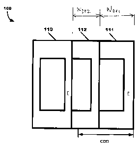
[0031] As illustrated in FIG. 1, an example multi-panel door system 100
comprises
a door having a plurality of door panels, including but not limited to a
stationary door panel
110, a first linearly moveable door panel 111, and a second linearly moveable
door panel
112 that are movable along a horizontal axis between an open position and a
closed
position. In the illustrated embodiment of FIG. 1, the door comprises two
linearly moveable
door panels. Embodiments, however, are not limited thereto, and thus, this
disclosure
contemplates the door comprising any suitable number of linearly moveable door
panels
that falls within the spirit and scope of the principles of this disclosure.
[0032] In accordance with one or more embodiments, the door may include
door
panels of varying, i.e., different widths. For example, the first linearly
moveable door panel
111 may have a first width wippi, and the second linearly moveable door panel
112 may
have a second width WDP2 that is different than the first width wippi. The
first width wippi
may be greater than second width WDP2.
[0033] As illustrated in FIGS. 2 and 3, the example multi-panel door
system 100
further comprises a dual-synchronization drive assembly 200 operable to drive
the door,
Page 5
Date Regue/Date Received 2022-09-27
i.e., the first linearly moveable door panel 111 and the second linearly
moveable door
panel 112, between an open position and a closed position. The dual-
synchronization
drive assembly 200 comprises an electro-mechanical actuation device 210, a
double or
dual gear unit 220, and a transmission assembly 230. The direction the first
linearly
moveable door panel 111 and the second linearly moveable door panel 112
respectively
advance between the open position and the closed position is indicated by
arrows in FIG.
2. In spite of the difference in widths, the dual-synchronization drive
assembly 200 causes
a synchronized movement of the first linearly moveable door panel 111 and the
second
linearly moveable door panel 112 at different linear speeds/velocities to
fully advance the
first linearly moveable door panel 111 and the second linearly moveable door
panel 112
to the open position or the closed position simultaneously.
ELECTRO-MECHANICAL ACTUATION DEVICE
[0034] The electro-mechanical actuation device 210 is operable to generate
an
actuation force. As further disclosed in detail herein, in accordance with one
or more
embodiments, the electro-mechanical actuation device 210 may be controlled by
a control
device 260 (FIG. 4) in a manner which optimizes the performance of the electro-
mechanical actuation device 210, and particularly, the multi-panel door system
100.
[0035] The electro-mechanical actuation device 210 may comprise an
electric drive
motor 211 that is operably connected to a gear box 212 (FIG. 7). The electric
drive motor
211 is operable to generate drive power to apply an amount of torque to an
output drive
shaft 213 that is rotatable in clockwise and counterclockwise directions to
drive dual gear
unit 220. Alternatively, this disclosure contemplates driving the dual gear
unit 220
manually by a person sliding the door panels 111, 112 via manually-applied
force. The
electric drive motor 210 may be implemented as a brushless motor, a variable
electric
motor, a servomotor, a stepper motor, and the like. Embodiments, however, are
not
limited thereto, and thus, this disclosure contemplates the electro-mechanical
actuation
device 210 comprising any suitable actuation device that falls within the
spirit and scope
of the principles of this disclosure.
[0036] As illustrated in FIGS. 4 and 5, a control device 260 is provided
to control
the electro-mechanical actuation device 210. The control device 260 comprises
one or
Page 6
Date Regue/Date Received 2022-09-27
more processors and a non-transitory memory operatively coupled to the one or
more
processors comprising a set of instructions executable by the one or more
processors to
cause the one or more processors to execute one or more one or more
instructions to
control the electro-mechanical actuation device 210. Examples of suitable non-
transitory
machine- or computer-readable storage medium include, but are not limited to:
RAM
(Random Access Memory), flash memory, ROM (Read Only Memory), PROM
(Programmable Read-Only Memory), EPROM (Erasable Programmable Read-Only
Memory), EEPROM (Electrically Erasable Programmable Read-Only Memory), field
programmable gate arrays (FPGAs), complex programmable logic devices (CPLDs),
fixed-functionality logic hardware using circuit technology such as, for
example,
application specific integrated circuit (ASIC), complementary metal oxide
semiconductors
(CMOS) or transistor-transistor logic (TTL) technology, registers, magnetic
disks, optical
disks, hard drives, or any other suitable storage medium, or any combination
thereof. As
an example, software executed on one or more computer devices or computer
systems
may provide functionality described or illustrated herein.
[0037]
In accordance with one or more embodiments set forth, described, and/or
illustrated herein, "processor" means any component or group of components
that are
configured to execute any of the processes described herein or any form of
instructions
to carry out such processes or cause such processes to be performed. The one
or more
processors may be implemented with one or more general-purpose and/or one or
more
special-purpose processors. Examples of suitable processors include graphics
processors, microprocessors, microcontrollers, DSP processors, and other
circuitry that
may execute software. Further examples of suitable processors include, but are
not
limited to, a central processing unit (CPU), an array processor, a vector
processor, a
digital signal processor (DSP), a field-programmable gate array (FPGA), a
programmable
logic array (PLA), an application specific integrated circuit (ASIC),
programmable logic
circuitry, and a controller. The one or more processors may comprise at least
one
hardware circuit (e.g., an integrated circuit) configured to carry out one or
more
instructions contained in program code. In embodiments in which there is a
plurality of
Page 7
Date Regue/Date Received 2022-09-27
processors, such processors may work independently from each other, or one or
more
processors in the plurality may work in combination with each other.
DUAL GEAR UNIT
[0038] As illustrated in FIGS. 4-8, the dual gear unit 220, supported by
the output
drive shaft 213, has a structural configuration that is operable to cause
synchronized
movement of the first linearly moveable door panel 111 and the second linearly
moveable
door panel 112 at different linear speeds/velocities in order that the first
linearly moveable
door panel 111 and the second linearly moveable door panel 112 fully reach the
open
position or the closed position simultaneously. The dual gear unit 220
comprises a
rotatable first gear 221 and a rotatable second gear 222 that, in an automated
embodiment, are respectively driven by the output drive shaft 213.
[0039] The first gear 221, having a first diameter dGi, includes a
plurality of external
gear teeth tGi. The second gear 222, having a second diameter dG2, has a
plurality of
external gear teeth tG2. In accordance with one or more embodiments, the first
gear 221
has an overall diameter that is greater than the overall diameter of the
second gear 222
(i.e., dGi > dG2). Meaning, the diameter ratio of the first gear 221 to the
second gear 222
is x:y, where x> y. Moreover, the first gear 221 has a greater number of
external gear
teeth than the second gear 222 (i.e., tGi > tG2). The ratio of external gear
teeth on the first
gear 221 and the second gear 222 determine the motion ratio and linear
speed/velocity
of the first linearly moveable door panel 111 and the second linearly moveable
door panel
112. The diameter ratio and the ratio of external gear teeth are adjustable to
accommodate performance objections.
[0040] Although the illustrated embodiment shows a dual gear unit 220 for
implementation in the example multi-panel door system 100, embodiments are not
limited
thereto. This disclosure contemplates the dual-synchronization drive assembly
200 may
include other suitable gear architectures. For example, the dual-
synchronization drive
assembly 200 may include gear architecture in which a plurality of gears is
not coupled
together, and thus, may operate independently of each other.
Page 8
Date Regue/Date Received 2022-09-27
TRANSMISSION ASSEMBLY
[0041] As illustrated in FIGS. 2, 4, 7, and 8, the transmission assembly
230
comprises a first transmission belt/pulley 231 and a second transmission
belt/pulley 232.
[0042] The first transmission belt/pulley 231 is operatively connected to
the first
gear 221 and a stationary main gear 225 to transmit the drive power of the
electro-
mechanical actuation device 210 to the first linearly moveable door panel 111.
The first
transmission belt/pulley 230, having a first belt length IBi , has a plurality
external teeth
that, in operation, mesh with or otherwise operatively engages the external
gear teeth of
the first gear 221 to bidirectionally advance the first linearly moveable door
panel 111
between the open position and the closed position. The second transmission
belt/pulley
232 is operatively connected to the second gear 222 and a stationary secondary
gear 226
to transmit the drive power of the electro-mechanical actuation device 210 to
the second
linearly moveable door panel 112. The second transmission belt/pulley 232,
having a
second belt length IB2, has a plurality external teeth that, in operation,
mesh with or
otherwise operatively engages the external gear teeth of the second gear 222
to
bidirectionally advance the second linearly moveable door panel 112
(simultaneously with
the bidirectional advancement of the first linearly moveable door panel 111)
between the
open position and the closed position. In accordance with one or more
embodiments, the
first transmission belt/pulley 231 is greater in size than the second
transmission belt/pulley
232. Meaning, the first transmission belt/pulley 231 has a belt length that is
greater than
the belt length of the second transmission belt/pulley 232 (i.e., IBi > IB2).
CARRIER ASSEMBLY
[0043] As illustrated in FIG. 4, the door system 100 further includes a
carrier or
carriage assembly 240 to operatively connect the first linearly moveable door
panel 111
and the second linearly moveable door panel 112 to the transmission assembly
230. The
carrier assembly 240 comprises a first carrier member 241 and a second carrier
member
242. As illustrated in FIGS. 5 and 8, a third carrier member 243 is operable
to connect to
a third door panel, which could be a stationary door panel or a linearly
moveable door
panel. One or more of the carrier members 241, 242, 243 may include one or
more wheel
Page 9
Date Regue/Date Received 2022-09-27
members 244 operable to roll along a portion or part of at least another
adjacent carrier
member along a horizontal axis.
[0044] The first carrier member 241 is operable to connect the first
linearly
moveable door panel 111 to the first transmission belt/pulley 231. The first
carrier member
241 may be implemented as a bracket or header that is connected at an upper
region
thereof to the first transmission belt/pulley 231 and at an opposite lower
region thereof to
the first linearly moveable door panel 111. The lower region of the bracket
may include
spaced-apart flanges that define a space or opening which is sized to receive
an upper
region or header of the first linearly moveable door panel 111. Embodiments,
however,
are not limited thereto, and thus, this disclosure contemplates the first
carrier member 241
being connected to the first linearly moveable door panel 111 via any suitable
connection
architecture.
[0045] The second carrier member 242 is operable to connect the second
linearly
moveable door panel 112 to the second transmission belt/pulley 232. The second
carrier
member 242 may be implemented as a bracket or header that is connected at an
upper
region thereof to the second transmission belt/pulley 232 and at an opposite
lower region
thereof to the second linearly moveable door panel 112. The lower region of
the bracket
may include spaced-apart flanges that define a space or opening which is sized
to receive
an upper region or header of the second linearly moveable door panel 112.
Embodiments,
however, are not limited thereto, and thus, this disclosure contemplates the
second carrier
member 242 being connected to the second linearly moveable door panel 112 via
any
suitable connection architecture.
[0046] The example and alternative embodiments described above may be
combined in a variety of ways with each other. It should be noted that the
present
disclosure may, however, be embodied in many different forms and should not be
construed as limited to the embodiments set forth herein; rather, the
embodiments set
forth herein are provided so that the disclosure will be thorough and
complete, and will
fully convey the scope of the invention to those skilled in the art.
Furthermore, the steps
and number of the various steps illustrated in the figures may be adjusted
from that
Page 10
Date Regue/Date Received 2022-09-27
shown. The accompanying figures and attachments illustrate exemplary
embodiments of
the invention.
[0047] For definitional purposes and as used herein, "connected" or
"attached"
includes physical or electrical, whether direct or indirect, affixed or
adjustably mounted.
Thus, unless specified, "connected" or "attached" is intended to embrace any
operationally functional connection.
[0048] As used herein, "substantially," "generally," "slightly" and other
words of
degree are relative modifiers intended to indicate permissible variation from
the
characteristic so modified. It is not intended to be limited to the absolute
value or
characteristic which it modifies but rather possessing more of the physical or
functional
characteristic than its opposite, and approaching or approximating such a
physical or
functional characteristic.
[0049] The terms "coupled," "attached," or "connected" may be used herein
to refer
to any type of relationship, direct or indirect, between the components in
question, and
may apply to electrical, mechanical, fluid, optical, electromagnetic, electro-
mechanical or
other connections. Additionally, the terms "first," "second," etc. are used
herein only to
facilitate discussion, and carry no particular temporal or chronological
significance unless
otherwise indicated. The terms "cause" or "causing" means to make, force,
compel, direct,
command, instruct, and/or enable an event or action to occur or at least be in
a state
where such event or action may occur, either in a direct or indirect manner.
[0050] Those skilled in the art will appreciate from the foregoing
description that
the broad techniques of the exemplary embodiments may be implemented in a
variety of
forms. Therefore, while the embodiments have been described in connection with
particular examples thereof, the true scope of the embodiments should not be
so limited
since other modifications will become apparent to the skilled practitioner
upon a study of
the drawings, specification, and following claims.
Page 11
Date Regue/Date Received 2022-09-27