Note : Les descriptions sont présentées dans la langue officielle dans laquelle elles ont été soumises.
WO 2021/225812
PCT/11S2021/029080
REAL-TIME PLANT DIAGNOSTIC SYSTEM AND METHOD FOR
PLANT PROCESS CONTROL AND ANALYSIS
STA ______________________________ IEMENT OF PRIORITY
[0001] This application claims the benefit of United States Provisional Patent
Application
Ser. No. 63/022,029, filed May 8, 2020, the entirety of which is incorporated
herein by
reference.
FIELD
100021 This disclosure is related to a method and system for controlling the
operation of a
plant, such as a chemical plant or a refinery, and more particularly, real-
time diagnostic
systems for managing plant process control and analysis using compositional
sensors.
BACKGROUND
[0003] A diagnostic system for monitoring a refinery unit is a feature of
controlling the
operation of the plant for early detection of fault conditions or a
compositional measurement
that is outside of a predetermined range. Facilitating a troubleshooting or
corrective action
for correcting the faulty condition or a compositional measurement that is
outside of a
predetermined range is a difficult task for a plant operator. A timely and
prompt corrective
action is needed to save operational expenses and time for an enhanced outcome
of the
plant. In certain cases, reviewing data related to the faulty condition or a
compositional
measurement that is outside of a predetermined range on a periodic basis is a
time-
consuming, complicated, and difficult process for the plant operator.
[0004] Conventional diagnostic systems lack the ability to provide analysis
reports rapidly,
in real-time, and mechanisms for direct and specific analysis notifications to
the plant
operator.
[0005] Conventional methods, mechanisms, sensors, and apparatuses do not
provide direct
and specific diagnostic analysis of a chemical process, which are necessary to
promptly
identify a root cause of a faulty condition or a compositional measurement
that is outside of
a predetermined range. Promptly identifying the root cause of the faulty
condition,
undesired measurements, or operational gaps may significantly reduce the
operational
-1 -
CA 03178050 2022- 11- 7
WO 2021/225812
PC T/US2021 /029080
expenses and time.
[0006] There remains a need for a diagnostic system and sensors that provide
direct and
specific diagnostic analysis of a chemical process in real-time.
SUMMARY
[0007] A general objective of the disclosure is to improve diagnostic
operation efficiency of
plants and refineries. A more specific objective of this disclosure is to
overcome one or
more of the problems described above. A general objective of this disclosure
may be
attained, at least in part, through a method for improving operation of a
plant. The method
may comprise obtaining direct and specific plant operation information from
the plant in
real-time.
[0008] In one embodiment of the present disclosure a method for improving
operation of a
plant may comprise obtaining plant operation information in real-time from the
plant and
generating a plant process model using direct and specific plant operation
information. The
model may be an outcome based business model that can improve process unit
control. The
method may comprise receiving plant operation information over the internet
and
automatically generating a plant process model using the direct and specific
plant operation
information.
[0009] In another embodiment of the present disclosure, compositional analysis
may be
used to monitor and/or optimize performance of individual process units,
operating blocks
and/or complete processing systems. Routine and frequent analysis of actual
performance
allows early identification of operational discrepancies which may be acted
upon to
optimize impact.
10010] In another embodiment of the present disclosure, the method of
obtaining plant
operation information may comprise using a web-based computer system or
platform. The
benefits of executing work processes within a web-based computer system or
platform
comprise improved plant performance due to an increased ability by operations
to identify
and capture opportunities in real-time, a sustained ability to bridge
performance gaps in
real-time, and improved enterprise management.
[0011] In another embodiment of the present disclosure, a data collection
system at a plant
may capture direct and specific data that may be automatically sent to a
remote location,
where it may be processed to, for example, eliminate errors and biases, and
may be used to
- 2 -
CA 03178050 2022- 11- 7
WO 2021/225812
PC T/US2021 /029080
calculate and report performance results. The performance of the plant and/or
individual
process units of the plant may be compared to other process models created by
the plant to
identify any operating differences or gaps.
[0012] In another embodiment of the present disclosure, a diagnostic report,
such as a daily
report, showing actual performance may be generated and delivered to one or
more devices,
via, for example, the internet or other wireless communication means. Any
identified
performance gaps or differences may be associated with the cause of the gaps
during the
processing of the data collected by the data collection system. Any identified
performance
gaps may be used to resolve the performance gaps. The method may comprise
using other
plant process models and operation information to run optimization routines
that converge
on an optimal plant operation for the given values of, for example, feed,
products, and
prices.
[0013] In another embodiment of the present disclosure, the method may
comprise
automatically generating recommendations to adjust process conditions allowing
the plant
to run continuously at or closer to optimal conditions. The method may provide
one or
more alternatives for improving or modifying the operations of the plant The
method may
regularly maintain and/or tune the process models to correctly represent the
true potential
performance of the plant based on one or more signals and parameters related
to the
operations of the plant. In one or more embodiments, the method may include
optimization
routines configured according to specific criteria, which may be used to
identify optimum
operating points, evaluate alternative operations, and/cm petfoint feed
evaluations.
[0014] In another embodiment of the present disclosure, a repeatable method
that will help
refiners bridge the gap between actual and achievable performance may be used.
The
method may use process development history, modeling and stream
characterization, and
plant automation experience to protect data security, and efficiently
aggregate, manage, and
move large amounts of data. Web-based optimization may be an enabler to
achieving and
sustaining maximum process performance by connecting, on a virtual basis,
technical
expertise and the plant process operations staff in real-time.
[0015] In another embodiment of the present disclosure, an enhanced workflow
may be
implemented and comprise using configured process models to monitor, diagnose,
predict,
and/or optimize performance of individual process units, operating blocks, or
complete
processing systems in real-time.
[0016] As used herein, references to a "routine" arc to be understood to refer
to a computer
program or sequence of computer programs or instructions for performing a
particular task.
- 3 -
CA 03178050 2022- 11- 7
WO 2021/225812
PCT/US2021/029080
References herein to a "plant" are to be understood to refer to any of various
types of
chemical manufacturing or refining facilities. References to "chemical"
includes
"petrochemical". References herein to a plant "operators" are to be understood
to refer to
and/or include, without limitation, plant planners, managers, engineers,
technicians, and
others interested in, overseeing, and/or running the daily operations at a
plant.
100171 The foregoing and other aspects and features of the present disclosure
will become
apparent to those of reasonable skill in the art from the following detailed
description, as
considered in conjunction with the accompanying drawings.
BRIEF DESCRIPTION OF THE DRAWINGS
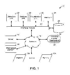
[0018] FIG. 1 depicts an illustrative functional block diagram of a diagnostic
system in
accordance with one or more embodiments of the present disclosure;
[0019] FIG. 2 depicts an illustrative flow diagram of processes in accordance
with one
or more embodiments of the present disclosure;
[0020] FIG. 3 depicts an illustrative process flow diagram for an example
chemical
plant showing example sensor locations in accordance with one or more
embodiments
of the present disclosure;
[0021] FIG. 4 depicts a top view of micro gas chromatographs in accordance
with one
or more embodiments of the present disclosure.
DETAILED DESCRIPTION
[0022] The following detailed embodiments presented herein are for
illustrative purposes.
That is, these detailed embodiments are intended to be exemplary of the
present invention
for the purposes of providing and aiding a person skilled in the pertinent art
to readily
understand how to make and use the present invention.
[0023] Accordingly, the detailed discussion herein of one or more embodiments
is not
intended, nor is it to be construed, to limit the boundaries of the
descriptions but rather as
defined by the claims and equivalents thereof. Therefore, embodiments not
specifically
addressed herein, such as adaptations, variations, modifications, and
equivalent
arrangements, should be and are considered to be implicitly disclosed by the
illustrative
- 4-
CA 03178050 2022- 11- 7
WO 2021/225812
PCT/US2021/029080
embodiments and claims set forth herein and therefore fall within the scope of
the present
invention.
[0024] Further, it should be understood that, although steps of various
claimed methods
may be shown and described as being in a sequence or temporal order, the steps
of any such
method are not limited to being carried out in any particular sequence or
order, absent an
indication otherwise. That is, the claimed method steps are considered capable
of being
carried out in any sequential combination or permutation order while still
falling within the
scope of the present invention.
[0025] Additionally, it is important to note that each term used herein refers
to that which a
person skilled in the relevant art would understand such term to mean, based
on the
contextual use of such term herein. To the extent that the meaning of a term
used herein, as
understood by the person skilled in the relevant art based on the contextual
use of such term,
differs in any way from any particular dictionary definition of such term, it
is intended that
the meaning of the term as understood by the person skilled in the relevant
art should
prevail.
[0026] Furthermore, a person skilled in the art of reading claimed inventions
should
understand that "a" and "an" each generally denotes "at least one," but does
not exclude a
plurality unless the contextual use dictates otherwise. Also, the term "or"
denotes "at least
one of the items," but does not exclude a plurality of items of the list.
[0027] In the description which follows, like parts are marked throughout the
specification
and drawings with the same reference numerals, respectively. The (hawing
figures may not
necessarily be to scale and certain features may be shown in somewhat
schematic form in
the interest of clarity and conciseness.
[0028] Referring now to FIG. 1, an illustrative diagnostic system, generally
designated
10, using one or more embodiments of the present disclosure is provided for
improving
operation of one or more plants (e.g., Plant A ... Plant N) 12a-12n, such as a
chemical
plant or refinery, or a portion thereof. The diagnostic system 10 may use
plant
operation information obtained from at least one plant of the one or more
plants 12a-
12n, which may be the current plant (e.g., Plant A) 12a, other third party or
customer
plants (e.g., Plant N) 12n, and/or proprietary services, subsidiaries, and the
like.
[0029] As used herein, the terms "system," "unit," or "module" may refer to,
be part of, or
include an Application Specific Integrated Circuit (ASIC), an electronic
circuit, a memory
(shared, dedicated, or group) and/or computer processor (shared, dedicated, or
group) that
- 5-
CA 03178050 2022- 11- 7
WO 2021/225812
PCT/US2021/029080
executes one or more software or firmware programs, a combinational logic
circuit, and/or
other suitable components that provide the described functionality.
[0030] Thus, while this disclosure comprises particular examples and
arrangements of the
units, the scope of the present system is not so limited, since other
modifications will
become apparent to the skilled practitioner. The software programs may be
written in
HTML5, CSS3, Java, JavaScript, PHP, HTML, C, C++, C#, AJAX, Python, Ruby,
Perl,
Objective-C, .NET, SQL, Ruby on Rails, Swift, Rust, Elixir, Go, Typescript, or
one or more
other suitable computer programming language.
[0031] The diagnostic system 10 may reside in or be coupled to a server or
computing
device 14 (including, e.g., database servers, video servers), and may be
programmed to
perform tasks and/or cause display of relevant data for one or more different
functional
units. Some or all relevant information may be stored in one or more databases
for retrieval
by the diagnostic system 10 or the computing device 14 (e.g., a data storage
device and/or a
machine-readable data-storage medium carrying computer programs).
[0032] The numerous elements of the diagnostic system 10 may be
communicatively
coupled through one or more networks (e.g., network 16). For example, the
numerous
platforms, devices, sensors, and/or components of the computing system
environment
illustrated in FIG. 1 may be communicatively coupled through a private
network. The
sensors may be positioned on various components in the plant and may
communicate
wirelessly or wired with one or more platforms. The sensors may be positioned
or located
in all key unit operations, such as chemical conversion units, separation
units, and process
devices. Chemical conversion units can be reactors, including hydroprocessing
units,
cracking units, and reforming units, furnaces, catalyst regenerators, and
absorbance units.
Separation units can be fractionation columns, and distillation columns,
filtration,
sedimentation, decantation, and crystallization units. Process devices can be
any equipment
employed in a chemical plant that is not a separation unit or a chemical
conversion unit,
such as pumps, compressors, heat exchangers, control valves, lines in fluid
communication
with said at least one chemical conversion unit or at least one separation
unit and/or
other process equipment commonly found in the refining and chemical industry.
[0033] The private network may comprise, in some examples, a network firewall
device to
prevent unauthorized access to the data and devices on the private network.
Alternatively,
the private network may be isolated from external access through physical
means, such as a
hard-wired network with no external, direct-access point. The data
communicated on
- 6-
CA 03178050 2022- 11- 7
WO 2021/225812
PC T/US2021/029080
the private network may be optionally encrypted for further security.
Depending on the
frequency of collection and transmission of sensor measurements and other
data, the
private network may experience large bandwidth usage and be technologically
designed
and arranged to accommodate for such technological issues. Moreover, the
computing
system environment may also include a public network that may be accessible to
remote devices. In some examples, a remote device (e.g., a remote device
associated
with a plant operator) may be located not in the proximity (e.g., more than
one mile
away) of the various sensor, measurement, and data capture systems (e.g.,
which may
be located at or near the one or more plants 12a-12n). In other examples, the
remote
device may be physically located inside a plant (e.g., a plant of the one or
more plants
12a-12n), but restricted from access to the private network; in other words,
the adjective
"remote," need not necessarily require the device to be located at a great
distance from
the sensor systems and other components. One or more other suitable networks
may be
used, such as the internet, a wireless network (e.g., Wi-Fi), a corporate
Intranet, a local
area network (LAN), a wide area network (WAN), and/or the like.
[0034] The diagnostic system 10 may be partially or fully automated. In one or
more
embodiments, the diagnostic system 10 may be performed by a computer system,
such
as a third-party computer system, remote from a plant of the one or more
plants 12a-12n
and/or the plant planning center. The diagnostic system 10 may include a web-
based
platform 18 that may send and/or receive information over a communication
network
(e.g., the intemet). Specifically, the diagnostic system 10 may receive
signals and/or
parameters via the network 16, and may cause display (e.g., in real time, in
substantially
real time, after a slight delay, after a long delay) of related performance
information on
an interactive display device (e.g., interactive display device 20).
10035] Using a web-based system may provide one or more benefits, such as
improved
plant performance due to an increased ability to identify and capture
opportunities, a
sustained ability to bridge plant performance gaps, and/or an increased
ability to leverage
personnel expertise and improve training and development. The method may allow
for
automated daily evaluation of process performance, thereby increasing the
frequency of
plant performance review with less time and effort from plant operations staff
Offline
collection of data from the sensors cannot be collected in real-time, and
increases the risk of
the data containing significant errors due to, at least, sample integrity
degradation or
ambient exposure of the samples to surrounding environmental impacts. Offline
collection
of data from the sensors can also be plagued by time stamp and synchronization
issues,
- 7 -
CA 03178050 2022- 11- 7
WO 2021/225812
PCT/US2021/029080
which reduce process reliability and optimization.
[0036] The web-based platform 18 may allow one or more users to work with the
standardized information, thereby creating a collaborative environment (e.g.,
for sharing
best practices or for troubleshooting). The method may provide more accurate
prediction
and optimization results due to fully configured models, which may include,
for example,
catalytic yield representations, constraints, degrees of freedom, and/or the
like. The models
may be outcome based business models that can improve process unit control.
Routine
automated evaluation of plant planning and operation models may allow timely
plant model
tuning to reduce or eliminate gaps between prepared plant models and direct
and specific
plant performance. Implementing the method using the web-based platform 18 may
allow
for monitoring and/or updating multiple sites, thereby better enabling
facility planners to
propose realistic optimal targets. The web-based platform 18 can allow
collection of data
gathered from the sensors via the internet, and allow for real-time plant
process control.
[0037] The diagnostic system 10 may comprise one or more computing platforms,
which
may comprise one or more communication interfaces configured to interface with
one or
more other computing platforms (e.g., via an interface module, a network); one
or more
databases; one or more processors; and/or memory storing computer-readable
instructions
that, when executed by the one or more processors, cause the one or more
computing
platforms to perform one or more actions or steps. In one or more embodiments,
the
diagnostic system 10 may be implemented as a computer program or suite of
computer
programs including instructions arranged such that when executed by one or
more
computers, the instructions cause the one or more computers to perform one or
more
functions described herein. One or more embodiments may comprise at least one
computer-
readable medium storing a computer program or at least one of the suite of
computer
programs. One or more embodiments may comprise an apparatus comprising at
least one
processor and memory storing instructions that, when executed by the at least
one processor,
cause the apparatus to perform one or more functions described herein. In one
or more
embodiments, the diagnostic system 10 may comprise a detection unit 22, an
analysis unit
28, a visualization unit 30, an alert unit 34, an interface module 24, a
server or computing
device 14, a web-based platform 18, and/or one or more additional devices,
platforms, or
systems.
[0038] The diagnostic system 10 may comprise a detection unit 22 configured to
detect a
faulty condition or at least one a compositional measurement that is outside
of a
- 8-
CA 03178050 2022- 11- 7
WO 2021/225812
PC T/US2021 /029080
predetermined range of the refining or chemical process of at least one plant
of the one or
more plants 12a-12n. In some refineries or chemical plants, various parameters
or
measurements might differ between different levels, pieces of equipment,
processes, or
other aspects of a plant (e.g., a plant of the one or more plants 12a-12n).
Consequently,
diagnosing different process models being executed may depend on different
parameters or
measurements. In some embodiments, the detection unit 22 may automatically
detect one or
more faulty conditions or a compositional measurement that is outside of a
predetermined
range based on readings of the parameters or measurements in real-time. The
detection unit
22 may generate one or more alerts associated with the detected one or more
faulty
conditions or a compositional measurement that is outside of a predetermined
range.
[0039] The diagnostic system 10 may use process measurements to monitor the
performance of chemical conversion units, separations units, and/or process
devices.
[0040] The diagnostic system 10 may use process measurements from various
sensor and
monitoring devices to monitor conditions in, around, and on process equipment.
Such
sensors may include, but are not limited to, pressure sensors, differential
pressure sensors,
various flow sensors (including but not limited to orifice plate type, disc,
venturi),
temperature sensors including thermal cameras and skin thermocouples,
capacitance sensors,
weight sensors, gas chromatographs, moisture sensors, ultrasonic sensors,
position sensors,
timing sensors, vibration sensors, level sensors, liquid level (hydraulic
fluid) sensors, and
other sensors commonly found in the refining and chemical industry. Further,
process
laboratory measurements may be taken using sensors such as gas chromatographs,
liquid
chromatographs, distillation measurements, octane number measurements, and
other
laboratory measurements (see FIGS. 3 and 4). System operational measurements
also can
be taken to correlate the system operation to the rotating equipment
measurements.
[0041] Gas chromatographs ("GC") are instruments used to perform gas
chromatography
analysis of samples. A GC can be a compositional sensor and used for
determining feed and
product compositions, degree of conversion to desired products or of specific
feed
constituents in plant operations. GC in the present disclosure can also refer
to liquid
chromatographs for performing liquid chromatography analysis of samples.
[0042] Compositional sensors directly and specifically analyze compositional
data related to
plant and are not model-dependent. Model-dependent sensing refers to
analytical methods
that are not based on a direct signal from the substance or process being
analyzed. Model-
dependent sensing comprises using physical properties, such as, but not
limited to, viscosity,
- 9 -
CA 03178050 2022- 11- 7
WO 2021/225812
PC T/US2021 /029080
refractive index, specific gravity, or spectroscopic measurements to
indirectly deduced
chemical composition through data correlations. Compositional sensors provide
composition and data beyond temperature, pressure, level, and flow. The data
collected
from compositional sensors can be used to improve reliability, efficiency, and
profitability
of a plant.
100431 GC analysis can be performed using a compositional analysis to provide
directly
measured compositional data to be used for process control. The directly
measured
compositional data can be measured automatically, or in an automated way. The
data
collected from the compositional sensors has a reduced potential for ambient
exposure or
degraded sample integrity because the data can be transmitted in real time,
according to one
or more embodiments of the present disclosure.
[0044] In addition, sensors may comprise transmitters and deviation alarms.
These sensors
may be programmed to set off an alarm, which may be audible and/or visual.
[0045] Other sensors may transmit signals to a processor or a hub that
collects the data and
sends the data to a processor.
[0046] Sensor data, process measurements, and/or calculations made using the
sensor
data or process measurements may be used to monitor and/or improve the
performance
of the equipment and parts making up the equipment. For example, sensor data
may be
used to detect that a desirable or an undesirable chemical reaction is taking
place within
a particular piece of equipment, and one or more actions may be taken to
encourage or
inhibit the chemical reaction. Chemical sensors may be used to detect the
presence of
one or more chemicals or components in the process streams, such as corrosive
species,
oxygen, hydrogen, and/or water (moisture). Chemical sensors may utilize gas
chromatographs, liquid chromatographs, distillation measurements, and/or
octane
number measurements. In another example, equipment information, such as wear,
efficiency, production, state, or other condition information, may be gathered
and
determined based on sensor data. The collection of the sensor data and process
measurements may be performed using an automated sampling of a process stream.
[0047] Sensor data may be automatically collected continuously,
intermittently, or at
periodic intervals (e.g., every second, every five seconds, every ten seconds,
every minute,
every five minutes, every ten minutes, every hour, every two hours, every five
hours, every
twelve hours, every day, every other day, every week, every other week, every
month, every
other month, every six months, every year, or another interval). Data may be
collected at
- 10-
CA 03178050 2022- 11- 7
WO 2021/225812
PC T/US2021 /029080
different locations at different intervals. For example, data at a known
problem area may be
collected at a first interval, and data at a spot that is not a known problem
area may be
collected at a second interval. The data collection platform may be automated
to
continuously or periodically (e.g., every second, every minute, every hour,
every day, once
a week, once a month) transmit collected sensor data to interface module 24
via network 16,
which may be nearby or remote from the one or more plants 12a-12n.
Transmitting the
collected sensor data to interface module 24 can be performed in real-time,
which is less
than 10 minutes from sampling the process stream, less than 5 minutes from
sampling the
process stream, less than 3 minutes from sampling the process stream, or less
than 1 minute
from sampling the process stream.
[0048] The detection unit 22 may identify a causal relationship that leads to
finding a root
cause of chemical process disruptions and/or poor process operations. For
example, the
detection unit 22 may identify one or more operational issues or faulty
conditions or a
compositional measurement that is outside of a predetermined range and prepare
a
systematic drill-down navigation to a set of potential root causes of the
process disruptions
and poor process operations.
[0049] The diagnostic system 10 may include an interface module 24 for
providing an
interface between the diagnostic system 10, the detection unit 22, the
analysis unit 28,
visualization unit 30, alert unit 34, one or more internal or external
databases 26, and the
network 16. The interface module 24 may receive data from, for example, plant
sensors,
parameters, and compositional measurements via the network 16, and other
related system
devices, services, and applications. The other devices, services, and
applications may
include, but are not limited to, one or more software or hardware components
related to the
one or more plants 12a-12n. The interface module 24 may also receive the
signals and/or
parameters (e.g., provided from one or more sensors) from a plant of the one
or more plants
12a-12n, which may be communicated to one or more respective units, modules,
devices,
and/or platforms.
[0050] The diagnostic system 10 may comprise an analysis unit 28 configured to
determine
an operating status of the refinery or chemical plant to ensure robust
operation of the one or
more plants 12a-12n. The analysis unit 28 may determine the operating status
based on the
readings of parameters or measurements gathered by one or more sensors at a
plant of the
one or more plants 12a-12n. The parameters or measurements may relate to at
least one of a
process model, a kinetic model, a parametric model, an analytical tool, a
related knowledge
- 11 -
CA 03178050 2022- 11- 7
WO 2021/225812
PC T/US2021 /029080
standard, and/or a best practice standard.
[0051] In one or more embodiments, the analysis unit 28 may generate a
comprehensive
process decision tree based on at least one of an expert knowledge or a causal
relationship
between the faulty condition or a compositional measurement that is outside of
a
predetermined range and the corresponding sensor signals, parameters, or
measurements.
Once the causal relationship is generated based on the decision tree, a human-
machine
interface ("HMI-) may be used to graphically link the faulty condition or a
compositional
measurement that is outside of a predetermined range with the signals,
parameters, or
measurements. In one embodiment, high level process key performance indicators
may be
shown on the alert dashboard 32 and/or the display device 20.
[0052] In one embodiment, the analysis unit 28 may receive historical or
current
performance data from at least one plant of the one or more plants 12a-12n.
The analysis
unit 28 may use the historical or current performance data to proactively
predict future
events or actions. To predict various limits of a particular process and stay
within the
acceptable range of limits, the analysis unit 28 may determine target
operational parameters
of a final product based on one or more actual current operational parameters
and/or one or
more historical operational parameters (e.g., from a process stream, a heater,
a temperature
set point, a pressure signal, and/or the like).
[0053] In using the kinetic model or other detailed calculations, the analysis
unit 28 may
establish one or more boundaries or thresholds of operating parameters based
on existing
limits and/or operating conditions. Illustrative existing limits may include
mechanical
pressures, temperature limits, hydraulic pressure limits, and/or operating
lives of various
components. Other suitable limits and conditions may suit different
applications.
[0054] In using the knowledge and best practice standard, such as specific
know-hows, the
analysis unit 28 may establish relationships between operational parameters
related to a
specific process. For example, the boundaries on a naphtha reforming reactor
inlet
temperature may be dependent on a regenerator capacity and hydrogen-to-
hydrocarbon
ratio. Furthermore, the hydrogen-to-hydrocarbon ratio may be dependent on a
recycle
compressor capacity.
[0055] The diagnostic system 10 may comprise a visualization unit 30
configured to display
plant performance variables using the display device 20. The visualization
unit 30 may
display a current state of the plant of the one or more plants 12a-12n using
an alert
dashboard 32 on the display device 20, grouping related data based on a source
of the data
- 12-
CA 03178050 2022- 11- 7
WO 2021/225812
PCT/US2021/029080
for meaningfully illustrating relationships of the displayed data. In this
configuration, the
user can quickly identify the information, and effectively gains insightful
interpretation
presented by the displayed data.
[0056] In one or more embodiments, the diagnostic system 10 may interface with
the
network 16, and perform the performance analysis of a given plant of the one
or more plants
12a-12n. The diagnostic system 10 manages interactions between the operators
and the
present system by way of the HMI, such as a keyboard, a touch sensitive pad, a
touchscreen,
a mouse, a trackball, a voice recognition system, and/or the like. Other
suitable interactive
interfaces may suit different applications.
[0057] The display device 20 (e.g., textual and graphical) may be configured
to receive an
input signal from the diagnostic system 10. In one or more embodiments, the
diagnostic
system 10 may receive graphical and/or textual input or interactions from an
input device,
such as the HMI, using the alert dashboard 32. The signals and/or parameters
may be
received in the diagnostic system 10 and then transferred to the alert
dashboard 32 of the
display device 20 via a dedicated and/or wireless communication system. The
display
device 20 can be a mobile device.
[0058] The diagnostic system 10 may comprise an alert unit 34 configured to
automatically
generate a warning message based on the received signals, parameters, or
measurements.
Illustrative warning messages may include, but are not limited to, an email, a
phone call, a
text message, a voice message, an iMessage, an alert associated with a mobile
application,
or the like, such that selected technical service personnel and customers are
informed of one
or more faulty conditions or a compositional measurement that is outside of a
predetermined
range of the specific chemical refining or chemical process.
[0059] Turning now to FIG. 2, an illustrative flow diagram of one or more
processes in
accordance with one or more embodiments of the present disclosure is shown.
One of skill
in the art will recognize that the flow diagrams depicted throughout this
disclosure may
include one or more additional steps, repeat steps, may be performed without
one or more
steps, and/or may be performed in a different order than depicted.
[0060] FIG. 2 depicts a flow diagram for an illustrative operation 36 of the
diagnostic
system 10. In step 38, the method may begin.
[0061] In step 40, the method may initiate a detecting unit. In one
embodiment, the
detection unit 22 may be initiated by a computer system that is inside or
remote from the
plant 12a-12n. The method may be automatically performed by the computer
system;
however, the present disclosure is not intended to be so limited. One or more
steps may
- 13-
CA 03178050 2022- 11- 7
WO 2021/225812
PCT/US2021/029080
include manual operations or data inputs from the sensors and other related
systems, as
desired.
[0062] In step 42, the method may obtain plant operation information. In an
example
operation, the detection unit 22 may receive at least one set of actual
measured data from the
plant 12a-12n on a recurring basis at a specified time interval, such as, for
example, every
100 milliseconds, every second, every ten seconds, every minute, every two
minutes, etc.
The received data may be analyzed for completeness and corrected for gross
errors. Then,
the data may be corrected for measurement issues (e.g., an accuracy problem
for
establishing a simulation steady state) and/or overall mass balance closure to
generate a
duplicate set of reconciled plant data.
[0063] In step 44, a plant process model may be generated using the plant
operation
information. The plant process model may estimate or predict plant performance
that may
be expected based upon the actual, specific, and directly collected plant
operation
information. The plant process model results can be used to monitor the health
of the plant
12a-12n and/or to determine whether any upset or poor measurement occurred.
The plant
process model may be generated by an iterative process that models various
plant
constraints to determine the desired plant process model.
[0064] The generated plant process model can further be divided into sub-
sections, though
this is not required in all methods. In an example method for creating sub-
sections, a
simulation may be used to model the operation of the plant 12a-12n. Because
the
simulation for the entire unit may be quite large and complex to solve in a
reasonable
amount of time, each plant 12a-12n may be divided into smaller virtual sub-
sections,
which may consist of related unit operations. An exemplary process simulation
unit,
such as a UNISIM Design Suite, is disclosed in U.S. Patent No. 9,053,260,
which is
incorporated by reference in its entirety.
[0065] For example, in one or more embodiments, a fractionation column and its
related
equipment such as its condenser, receiver, reboiler, feed exchangers, and
pumps may
make up a sub-section. Some or all available plant data from the unit,
including
temperatures, pressures, flows, and/or laboratory data may be included in the
simulation
as Distributed Control System (DCS) variables. Multiple sets of the plant data
may be
compared against the process model, and model fitting parameter and
measurement
offsets may be calculated that generate the smallest errors.
[0066] In step 46, offsets may be calculated based on measurements and/or
model
values. Fit parameters or offsets that change by more than a predetermined
threshold,
- 14-
CA 03178050 2022- 11- 7
WO 2021/225812
PCT/US2021/029080
and measurements that have more than a predetermined range of error, may
trigger
further action. For example, large changes in offsets or fit parameters may
indicate the
model tuning may be inadequate. Overall data quality for the set of data may
then be
flagged as questionable.
[0067] A measured value and corresponding stored value (which may be simulated
or
actual value collected from prior plant process data) may be evaluated for
detecting an
error or excess deviation based on a corresponding offset. In one or more
embodiments, an offset may be detected when the measured information is not in
sync
with, the same as or in the range of the stored information used as the
process model.
The system may use evidence from a number of measurements and a process model
to
create the stored information.
[0068] In step 48, the operational status of the measurements may be
diagnosed, e.g., based
on at least one environmental factor, and a fault (or faults) may be detected
by the detection
unit 22. As discussed elsewhere herein, the example diagnostic system 10 may
use one or
more different models to determine the status of the plant and the presence of
operating
conditions that may be considered faults. A model used for detecting the
faults can be a
heuristic model, an analytical model, a statistical model, etc. In one or more
example
methods, the calculated offset between the feed and product information may be
evaluated
based on at least one environmental factor for detecting the fault of a
specific measurement.
[0069] In step 50, the analysis unit 28 may determine fault relationships and
consequences.
Relationships between the faults can be determined from, for instance, expert
knowledge,
statistical analysis, or machine learning. In one or more embodiments, the
analysis unit 28
may generate a comprehensive process decision tree based on at least one of an
expert
knowledge or a causal relationship between the faulty condition or a
compositional
measurement that is outside of a predetermined range and the corresponding
sensor signals,
parameters, or measurements.
[0070] In one or more embodiments, the analysis unit 28 can receive historical
or current
performance data from at least one of the plants 12a-12n to proactively
predict future
actions to be performed. To predict various limits of a particular process and
stay within the
acceptable range of limits, the analysis unit 28 may determine target
operational parameters
of a final product based on actual current and/or historical operational
parameters, e.g., from
a process stream, a heater, a temperature set point, a pressure signal, or the
like.
[0071] In using the kinetic model or other detailed calculations, the analysis
unit 28 may
establish boundaries or thresholds of operating parameters based on existing
limits and/or
- 15-
CA 03178050 2022- 11- 7
WO 2021/225812
PCT/US2021/029080
operating conditions. Illustrative existing limits may include mechanical
pressures,
temperatures, hydraulic pressures, compositions and/or operating lives of
various
components. Other suitable limits and conditions are contemplated to suit
different
applications.
[0072] In using the knowledge and best practice standard, such as specific
know-hows, the
analysis unit 28 may establish relationships between operational parameters
related to the
specific process. For example, the boundaries on a naphtha reforming reactor
inlet
temperature may be dependent on a catalytic regenerator capacity and/or a
hydrogen-to-
hydrocarbon ratio, which itself may be dependent on a recycle gas compressor
capacity.
[0073] Next, in step 52, the visualization unit 30 may cause one or more
displays, such as
the display device 20, to be updated. The display device 20 may be configured
for
graphically linking the faulty condition or a compositional measurement that
is outside of a
predetermined range detected by the detection unit 22 with the plurality of
readings of
parameters or measurements. The visualization unit 30 may display a current
state of the
plant 12a-12n, e.g., the operating status of the plant with the readings of
parameters or
measurements, using an alert dashboard 32 on the display device 20, grouping
related data
based on a source of the data for meaningfully illustrating relationships of
the displayed
data.
[0074] The visualization unit 30 may update one or more screens of the display
device 20
with context information that is provided by diagnosing measurements and
detecting faults
and by determining fault relationships and consequences. For example, once the
causal
relationship is generated based on the decision tree, a human machine
interface (HMI) may
be used to graphically link the faulty condition or a compositional
measurement that is
outside of a predetermined range with the signals, parameters, or
measurements. The
vizualization unit 30 may generate an alert. In some example methods, high
level process
key performance indicators (KPI) may be shown on the display device 20. If the
diagnostic
system 10 determines that conditions exist that might cause a key performance
indicator to
eventually be put at risk, the updated display devices 20 may indicate this
information,
provide context for what variables or factors are presenting this risk, and/or
provide advice
as to how to address the risk. In this configuration, a user may quickly
identify the
information, in real-time, and effectively gain insightful interpretation
presented by the
displayed data.
[0075] In one or more embodiments, the diagnostic system 10 may interface with
the
network 16, and perform the performance analysis of the given plant 12a-12n.
The
- 16-
CA 03178050 2022- 11- 7
WO 2021/225812
PCT/US2021/029080
diagnostic system 10 may manage interactions between the operators and the
present system
by way of the HMI, such as a keyboard, a touch sensitive pad or screen, a
mouse, a
trackball, a voice recognition system, and the like. Other suitable
interactive interfaces are
contemplated to suit different applications.
[0076] In some embodiments, the display device 20 (e.g., textual and
graphical) may be
configured for receiving an input signal from an input device and/or the
diagnostic system
10. In one embodiment, display may receive input from an input device, such as
the HMI,
the input indicating a graphical or textual interaction with the diagnostic
system 10, via the
alert dashboard 32. The signals and/or parameters may be generally received in
the
diagnostic system 10 and then transferred to the alert dashboard 32 of the
display device 20
via a dedicated communication system. The display device 20 may be a mobile
device.
[0077] The diagnostic system 10 may determine at step 54 whether to send one
or more
notifications. In one or more example embodiments, the diagnostic system 10
can be
configured to set up notifications to individual users. Alternatively or
additionally, users
can subscribe to notifications.
[0078] If a measurement is determined to be within a fault status or undesired
status, a
notification (e.g., an alert) may be sent to a user device (e.g., of an
operator) at step 58. The
diagnostic system 10 may include an alert unit 34 configured for automatically
generating
alerts such as a warning message for the operators and/or other related
systems coupled to
the present system based on the received signals, parameters, or measurements.
Exemplary
warning messages may include, but are not limited to, an email, a text
message, a voice
message, an iMessage, a smartphone alert, a notification from a mobile
application, or the
like. The alert may provide information related to one or more faulty
conditions or a
compositional measurement that is outside of a predetermined range of the
specific
chemical refining or chemical process.
[0079] After the notification is sent (step 58), or if no notification is
required (step 54), the
method ends at step 56. The method may be repeated as needed
[0080] Turning now to FIG. 3, an illustrative process flow diagram 60 for an
example
plant showing example sensor 62 locations in accordance with one or more
embodiments of the present disclosure. At least one sensor 62, including gas
chromatograph or liquid chromatograph, or gas-liquid chromatograph sensor, can
be located
anywhere in the plant process. The at least one sensor 62 can be associated
with key unit
operations 64, such as a reactor, including hydroprocessing reactors, cracking
reactors,
reformers, furnaces and catalyst regenerators, a separations unit, including
fractionation
- 17-
CA 03178050 2022- 11- 7
WO 2021/225812
PCT/US2021/029080
columns and distillation columns, furnaces, cooling towers, and/or boilers.
The at least one
sensor 62 can be located within or positioned near key unit operations 64. The
at least one
sensor 62 can also be associated with, for example located within or
positioned near, a
process device 66, such as a valve, a duct, pipe or line, a compressor, a
pump, a turbine, a
separator, a drum, vessel or tank, and/or heat exchanger. The at least one
sensor 62 can also
be located or positioned upstream, midstream, or downstream of the plant
process.
100811 FIG. 3 is presented as an example only, and this disclosure is not
intended to be
limited to an oil refining process. The embodiments in this disclosure can
also be applied to
a plant, such as a chemical plant that uses natural gas as a feedstock.
Typically, key unit
operations 64 are in fluid communication with each other, and at least one
processes device
66 can be placed between each of the key unit operations 64. At least one
sensor 62 can be
located in between any key unit operation 64 that are in fluid communication
with each
other, a key unit operation 64 and a process device 66 that are in fluid
communication with
each other, or in between any process devices 66 that are in fluid
communication with each
other. At least one sensor 62 and be placed upstream or downstream of any key
unit
operation 64. At least one sensor 62 can also be integrated in or connected to
at least one
process device 66, at least one instrument, or key unit operation 64, or
integrated within
process equipment in the plant.
[0082] Turning now to FIG. 4, a top view of micro gas chromatographs 84 in
accordance
with one or more embodiments of the present disclosure is shown. A micro gas
chromatograph ("micro GC") 84 comprises the same components as a GC, but the
components are miniaturized, particularly the separation column(s), to
increase portability,
decrease power consumption, and increase the speed of analysis. Micro GC 84 in
the
present disclosure can also refer to micro liquid chromatographs for
performing liquid
chromatography analysis of samples. A micro GC 84 can provide rapid delivery
of
analytical data because a micro GC 84 separates analyte compounds at a higher
speed
compared to conventional GCs, particularly capillary GCs. The higher speed
allows for
faster analysis of data that can be up to 25 times faster than conventional GC
analysis.
[0083] In one embodiment of the present disclosure, a micro GC 84 or a micro
GCxGC 76
analysis can be used to directly measure compositions of process streams
comprising certain
substances to be analyzed. GCxGC is a multidimensional gas chromatography
technique
that can utilize at least two different columns with two different stationary
phases. In
GCxGC, effluent from the first dimension column is diverted to the second
dimension
column via a modulator. The modulator quickly traps, then "injects" the
effluent from the
- 18-
CA 03178050 2022- 11- 7
WO 2021/225812
PCT/US2021/029080
first dimension column onto the second dimension. This process creates a
retention plane of
the 1st dimension separation x 2nd dimension separation. A micro GCxGC
comprises the
same components as a GCxGC, but the components are miniaturized, to increase
portability,
decrease power consumption, and increase the speed of analysis. A single micro
GC 84 or
micro GCxGC 76 can be adapted to a range of analysis needs for various process
streams.
A standard GC apparatus can be substituted for a micro GC apparatus, or a
standard
GCxGC apparatus can be substituted for a micro GCxGC apparatus.
[0084] As shown in FIG. 4, in one embodiment of the present disclosure, a
plurality of
micro GCs 84, a plurality of micro GCxGCs 76, or a combination thereof, may be
employed, either in parallel, linear series, non-linear series, or combined in
a single sensing
instrument. A plurality of micro GC 84 or micro GCxGC 76 can comprise at least
two
micro GCs 84, micro GCxGCs 76, or a combination thereof, arranged to allow
fluid
communication between or among the micro GCs 84, micro GCxGCs 76, or
combination
thereof. The plurality of micro GCs 84, micro GCxGCs 76, or combination
thereof, can
allow for improved quality control of measurement processes. The overlapping
analytical
data received from the plurality of micro GCs 84, micro GCxGCs 76, or
combination
thereof, can be compared and provide a means for detecting measurement errors
in a
specific micro GC 84 or micro GCxGC 76 apparatus housed within the series or
single
sensing instrument employed in the plant.
[0085] In one embodiment of the present disclosure, the plurality of micro GCs
84, micro
GCxGCs 76, or combination thereof, can be confined to a single circuit board
or a silicon
chip based apparatus, and can be etched into a chip. A sample stream inlet 70
(which can be
a sample gas or liquid supply) can be integrated into the silicon chip-based
apparatus. A He
purge gas inlet 72 can also be integrated into the silicon chip-based
apparatus. The sample
gas inlet 70 allows a portion of a stream flowing through or from a plant or
refinery to enter
a micro GC characterization system 68. The sample gas inlet 70 and He purge
gas inlet 72
(if desired) can be in fluid communication with a switching valve 78, such as
a six-port
switching valve. The gas entering the switch valve 78 can be directed into a
column 74,
such as a trapping column. The sample stream can exit the column 74 and enter
the
switching valve 78, which can direct the gas to a micro GC 84 or micro GCxGC
76 though
a line 82. Line 82 can be a capillary tube. The switching valve 78 and column
74 can be
located inside an oven 80 to control the temperature of the gas and column 74.
[0086] A micro GC vacuum pump 86 can be built in to the micro GCxGC 76 to
assist with
pulling the gas into the micro GC 84 or micro GCxGC 76. The micro GC vacuum
pump
- 19-
CA 03178050 2022- 11- 7
WO 2021/225812
PCT/US2021/029080
can comprise a pump vent 88.
[0087] The switching valve 78 can be in fluid communication with a flow
selection valve
90. The flow selection valve 90 can be in fluid communication with a needle
valve 94 (if
desired) that is located between a vacuumeter 96 and flow selection valve 90.
The flow
selection valve 90 can control switching between enrichment and sample
transfer to the
micro GC 84 or micro GCxGC 76. The needle valve 94 can be used to adjust the
pressure
drop of the column 74 to the desired value.
[0088] In one embodiment of the present disclosure, a micro GC
characterization system
can be implemented downstream in the plant process, such as downstream of a
feed tank
containing a material that has been refined and is not in its natural state.
Analysis methods,
such as the UOP method 690(TM) standard and UOP method 744(TM) standard can be
miniaturized and used in combination with each other or a third method to
identify aromatic
isomer distribution for A6-A10, non-aromatic isomer distribution for C5-C8,
carbon
number, and carbon type information across the entire sample boiling range.
All three
methods do not need to be used at once. Micro UOP method 690 can be used to
identify
non-aromatic isomer distribution data for C5-C8. Micro UOP method 744 can be
used to
identify aromatic isomer distribution for A6-Al 0. The third method can be
used to identify
carbon number and carbon type information across the entire sample boiling
range by
utilizing GCxGC or micro GCxGC ("GCxGC method"). Each of these methods can be
used with GCxGC or micro GCxGC Combining the data collected from all three
methods
provides a full characterization report for a substance, such as for naphtha
range material.
One method, however, may provide all the data needed, and there may not be a
need to
combine any methods. Combining at least two of these methods can provide an
overlap of
data, fill in data gaps that one of the methods does not provide, and allow
for improved
quality control. Data quality can be checked by looking at common components
between
each method. Table 1 below provides an example of what substances can be
analyzed using
different combinations of micro UOP method 690, micro UOP method 744, and
GCxGC
method. These methods can be found on the ASTM International web site and the
path to
find these methods is currently Products and Services/Standards &
Publications/Standards
Products.
- 20-
CA 03178050 2022- 11- 7
WO 2021/225812
PC T/US2021/029080
Table 1
Substance to Be Detected Method or Method Combination
Benzene Micro UOP method 690, Micro UOP 744,
and
GCxGC
Toluene Micro UOP method 690, Micro UOP 744,
and
GCxGC
Xylenes Micro UOP 744 and GCxGC
Cyclohexane Micro UOP method 690 and GCxGC
Hexane Micro UOP method 690 and GCxGC
Heptane Micro UOP method 690 and GCxGC
Total A9 Micro UOP method 744 and GCxGC
Total A10 Micro UOP method 744 and GCxGC
Xylene Isomers Micro UOP method 744
[0089] Analysis methods quantify the chemical composition of a substance. The
UOP
method 690 is used to determine C8 and lower boiling paraffins and naphthenes
in
hydrocarbons containing less than 2 mass-% olefins (see Note 1) having a
maximum final
boiling point of 260 C. Benzene and toluene are also determined. Certain non-
aromatic
components of interest are reported as composites and C8 aromatics are not
determined.
[0090] The UOP method 744 is used to determine individual C6 through C10
aromatic
compounds in petroleum distillates or aromatic concentrates having a final
boiling point of
210 C or lower. C11 and heavier aromatics are reported as a group. C10 and
heavier non-
aromatics may interfere with the determination of benzene and toluene. When
this occurs,
benzene and toluene can be determined by ASTM Methods D 5443, D 5580, D 6729,
or D
6839, or UOP Method 690. Other applications for this method include the assay
of any C10
or lower boiling aromatics, such as benzene, toluene, mixed xylenes, etc. This
method may
also be used to provide a distribution of C8 aromatics and/or C9 and heavier
aromatics to a
value determined by a different method.
[0091] It is important to recognize that this disclosure has been written as a
thorough
teaching rather than as a narrow dictate or disclaimer. Reference throughout
this
specification to "one embodiment", "an embodiment", or "a specific embodiment"
means
- 21 -
CA 03178050 2022- 11- 7
WO 2021/225812
PCT/US2021/029080
that a particular feature, structure, or characteristic described in
connection with the
embodiment is included in at least one embodiment and not necessarily in all
embodiments.
Thus, respective appearances of the phrases "in one embodiment", "in an
embodiment", or
"in a specific embodiment" in various places throughout this specification are
not
necessarily referring to the same embodiment. Furthermore, the particular
features,
structures, or characteristics of any specific embodiment may be combined in
any suitable
manner with one or more other embodiments. It is to be understood that other
variations and
modifications of the embodiments described and illustrated herein are possible
in light of
the teachings herein and are to be considered as part of the spirit and scope
of the present
subject matter.
[0092] It will also be appreciated that one or more of the elements depicted
in the
drawings/figures can also be implemented in a more separated or integrated
manner, or even
removed or rendered as inoperable in certain cases, as is useful in accordance
with a
particular application. Additionally, any signal arrows in the
drawings/Figures should be
considered only as exemplary, and not limiting, unless otherwise specifically
noted.
Furthermore, the term "or" as used herein is generally intended to mean
"and/or" unless
otherwise indicated. Combinations of components or steps will also be
considered as being
noted, where terminology is foreseen as rendering the ability to separate or
combine is
unclear.
[0093] The foregoing description of illustrated embodiments, including what is
described in
the Abstract and the Summary, and all disclosure and the implicated industrial
applicability,
are not intended to be exhaustive or to limit the subject matter to the
precise forms disclosed
herein. While specific embodiments of, and examples for, the subject matter
are described
herein for teaching-by-illustration purposes only, various equivalent
modifications are
possible within the spirit and scope of the present subject matter, as those
skilled in the
relevant art will recognize and appreciate. As indicated, these modifications
may be made in
light of the foregoing description of illustrated embodiments and are to be
included, again,
within the true spirit and scope of the subject matter disclosed herein.
[0094] Thus, although the foregoing disclosure has been described in some
detail by way of
illustration and example for purposes of clarity and understanding, it will be
obvious that
certain changes and modifications may be practiced within the scope of the
disclosure, as
limited only by the scope of claims.
- 22-
CA 03178050 2022- 11- 7