Note : Les descriptions sont présentées dans la langue officielle dans laquelle elles ont été soumises.
WO 2021/233814
PCT/EP2021/062962
1
MANUFACTURING PROCEDURE FOR LABORATORY
INTEGRATED ON A CHIP
DESCRIPTION
Technical field
The present invention belongs to the area of laboratories integrated on a chip
(or
lab-on-chips)
The invention is applied in areas such as health, veterinary, industrial,
chemical,
environmental, agri-food and pharmaceutical areas, by way of example. It can
be
used for PCR (polymerase chain reaction) devices, DNA analysis, parameter
analysis systems, portable or not, such as creatinine or tumor markers, for
measuring pH in fluids, for performing gas or pollutant sensors, for the
manufacture of reactive or digester devices, the detection of compounds in
foods,
such as volatile compounds in olive oil or for the production and testing of
drugs.
Background of the invention
Lab-on-chips are booming due to their potential application in different
sectors
such as pharmaceutical or agri-food. One of the most interesting applications
of
these technologies is the manufacture of traditional analysis systems but on a
miniaturized scale. This application has some improvements compared to
traditional systems, such as the reduction in the amount of reagents required
and
of a significant part of the cost of the current analyzes; the automation of
the
processes using an attached electronics that affects the process in question
choosing when each step of the process occurs and reading the result once it
has been completed; faster analytics due to the reduction in the amount of
fluids
involved in the process; the possibility of making the entire system portable,
so
that analytics are allowed in places where an electrical connection is not
available and, due to all the previous improvements, a reduction in the cost
of the
entire process.
In the future, these technologies will make it possible to replace traditional
CA 03179606 2022- 11- 21
WO 2021/233814
PCT/EP2021/062962
2
analytical systems, such as clinical laboratories or food analysis
laboratories,
reducing the cost of analytics that we know today by several orders of
magnitude.
This will also allow the elimination of second medical visits for the reading
of
results by a medical team to a patient.
The problems still pending in the manufacture of this type of device are due
to
the high cost of the materials used and of the manufacturing processes, which
are also slow and difficult to industrialize and do not allow serial
manufacturing
processes.
Summary of the invention
The invention consists of a fast, more economical and easily reproducible
manufacturing process where the lab-on-chip is made up of successive layers of
biocompatible material that integrate printed electronic circuits in
biocompatible
conductive material between layers, which connect actuators and sensors
designed in the electronic circuit itself or embedded in contact with it,
which are
combined with a three-dimensional microchannel system that runs through the
various layers or their intersections with all kinds of structures designed
for the
desired analysis functionalities, such as measuring chambers, filters,
decanters,
etc. The microchannels are connected to chambers for introducing fluids, such
as
chemical reagents or samples, which are driven by electronically controlled
bidirectional pistons. Printed electronic circuits have external connections
to other
external electronic components or systems that can be used to supply, control
or
interpret the signals coming from the chip.
To solve the technological challenges necessary for the manufacture of such a
chip, a layered manufacturing process has been designed where all the layers
are made of a biocompatible material, such as, for example, without
limitation,
PMMA (polymethylmethacrylate), COC, polycarbonate, silicon, etc.
The manufacturing process includes metallizing those surfaces of biocompatible
material in which it is desired to integrate bicompatible printed electronic
circuits.
Metallization is based on the adhesion of a prefabricated metal layer to the
CA 03179606 2022- 11- 21
WO 2021/233814
PCT/EP2021/062962
3
biocompatible substrate through the use of a resin. The resin is removed once
the pattern of the tracks in the metal is generated by photolithography, so
that the
surface that will be in contact with the liquids or samples will be made of
biocompatible polymer or metal. In this way, a metallized biocompatible
substrate
is achieved in which it is possible to generate printed circuits by
traditional
methods and add active electronic components within the biocompatible
structure
without having to resort to high-cost metals or highly specialized
manufacturing
methods.
In the different layers of biocompatible material, microchannels or holes are
engraved, cut, drilled or stamped (by laser, for example), which, once the
different layers or substrates of, for example, polymer, are joined, they make
up
the microchannels, house the electronic components, make up the drive system
or define the physical separations of each area of the chip.
Like printed electronic circuits, the laboratory also includes electronic
sensors
and actuators built into the layers of the device. The sensors measure
physical
parameters such as temperature, pH, luminosity, etc. and they are linked to a
mechanical drive system and an electronic board. The data recorded by the
sensors is processed and interpreted in a processor. In this way, it is
possible to
carry out a control of the test conditions within the chip, measuring and
operating
on parameters such as temperature, or operating within the analytical process
by
means of, for example, light emitters or receivers. This is possible due to
the fact
that the contact of fluids with the metallic layer always takes place at
points
expressly designed for this purpose, the non-biocompatible electronic
components being isolated inside watertight cavities and connected through the
conductive layer.
Brief description of drawings
To complement the description that is being made and in order to help a better
understanding of the features of the invention, a set of figures is included
as an
integral part of said description where, by way of illustration and not
limitation, the
following has been represented:
CA 03179606 2022- 11- 21
WO 2021/233814
PCT/EP2021/062962
4
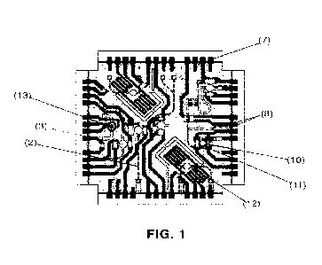
Figure 1.- Plan view of a laboratory on chip according to the invention.
Figure 2.- 3D view of the laboratory according to the invention
Figure 3.- Plan [A] and section [B] view of a laboratory on chip of the
invention.
Figure 4.- Sectional view of the manufacturing process of the upper layer of
the
microfluidic chip of Figure 3.
Figure 5.- Sectional view of the manufacturing process of the intermediate
layer
of the microfluidic chip of Figure 3.
Figure 6.- Sectional view of the manufacturing process of the lower layer of
the
microfluidic chip of Figure 3.
Figure 7.- Sectional view of the process for bonding the upper [A],
intermediate
[B] and lower [C] layers to give rise to the complete microfluidic chip [D]
Description of the invention
The invention consists of a laboratory integrated on a chip and its
manufacturing
process. The laboratory has the following features:
a) One or several three-dimensional structures of biocompatible
microchannels and susceptible to thermal processes limited by the melting
temperature of the substrate material, which allow i) to perform on a
simultaneous basis processes with different performance requirements on the
same sample or different types of samples, ii) incorporate microfluidic
processes
that use physical effects that occur in three-dimensional structures such as
decanting of particles in suspension in a fluid without incorporating filters
or iii)
physically section different areas of the chip to isolate them as required
(chemical, thermal or optical insulation).
b) One or more biocompatible printed electronic circuits, which allow i)
measuring and internally operating on microfluidic processes locally (only on
one
area of the chip), ii) heating only one area of the chip and making exact
measurements on it without affecting the rest of the processes carried out
therein, being able to transmit electrical signals in the desired areas of the
chip,
both to carry out electronic readings and to operate actuators (heaters,
lights,
sensors, etc.) integrated on the chip, iii) generating active structures such
as
heaters, electrodes or antennas using the electrical track design itself, iv)
CA 03179606 2022- 11- 21
WO 2021/233814
PCT/EP2021/062962
incorporating electronic components (sensors or actuators) connected to the
electrical tracks within the chip itself, which are in contact with or very
close to the
fluids or areas that may require them, or v) ensuring complete electrical
connectivity of the chip with any actuator, sensor or external controller.
5
With reference to Figure 1, a laboratory on chip according to the invention is
provided with multiple microchannels (2) in which measurement or reaction
chambers (3) are located where analyzes are carried out. It also contains a
printed electronic circuit (7) in which several thermal actuators have been
defined
in the form of heaters (12), several sensors in the form of electrodes (13)
and
electronic components (10) have been included. Fluidic processes such as
mixing, filtering, decanting or heating of fluids will be carried out in the
microchannels.
In Figure 3, a drive layer can be seen, wherein a fluid (4) separated from an
external drive system (not shown in the figures) is encapsulated by means of a
piston (5); an intermediate layer wherein the measurement or reaction chamber
is located (3); and a metallic lower layer with a printed electronic circuit
(7) on
which there are electronic components, sensors (10) and actuators (11) that
carry out measurements and the control of processes of the measurement and
reaction chamber (3). All the microchannels (2) of the different layers are
connected to each other and to the outside of the chip through holes (8). The
printed electronic circuit communicates with the outside through electronic
contacts (6) defined for this purpose.
The manufacturing method of the invention comprises, in a first step, the
design
by means of methods implemented by a complete chip processor with all the
channels, circuits and actuators that it will require for a specific analytic.
This
design is carried out on a computer, for example, with a suitable program,
such
as AutoCADO and the like.
The manufacture of the upper layer as shown in Figure 4, begins with the use
of
the base material (1) from which a reduced-size part is obtained that is
subsequently machining, for which some of the usable processes are CNC
CA 03179606 2022- 11- 21
WO 2021/233814
PCT/EP2021/062962
6
machining, laser ablation and injection molding of thermoplastic parts or hot
embossing. By means of said machining the through holes (8, figures 4B, 4C)
and the microchannels (2, figure 4D) joined by said holes are created.
In Figure 5 the method of manufacturing the intermediate layer of the
microfluidic
chip of Figure 3 can be seen. In the method the measurement chambers (3) and
also the cavities (15) that house the electronic components inside once the
layers
are bonded, are manufactured.
In Figure 6, the method of manufacturing the lower layer of the chip in Figure
3
can be seen. Starting [A] with a biocompatible substrate (1), the
metallization
process [B] is carried out, from which the printed circuit will emerge (7). A
photoresin (9) is deposited on the metal layer [C] to allow performing a
developing process by photolithography [D] and acid attack [E] to manufacture
the biocompatible printed electronic circuit. Once the exposed bonding resin
(6)
has been removed [F], the necessary microchannels and through holes (8) [G]
are manufactured. In this case there are only through holes (8).
Finally, before bonding the layers that make up the microfluidic chip, the
actuators (10) and sensors (11) or heaters are placed on the areas of the chip
designed for them [H]. In other implementations, heaters or antennas can be
added.
More particularly, the biocompatible metal layer can be deposited by methods
such as electroplating, sputtering, or adhering metal foil to the substrate. A
functionalization process is carried out on this metallic layer by means of
photolithography, firstly depositing a layer of photosensitive resin (6) that
will be
selectively activated by exposing specific areas of the surface using
photosensitive resin sensitizing agents (ultraviolet, visible or infrared
light
depending on the type of photosensitive resin). Once the resin is exposed, the
resin will be developed and the metal deposited on the sensitized areas of
said
resin by an etching or chemical etching process will be removed, generating a
specific metallization pattern as previously set forth. Metallization is
performed
with a conductive biocompatible material such as aluminum, gold, titanium, ITO
CA 03179606 2022- 11- 21
WO 2021/233814
PCT/EP2021/062962
7
or nitinol, from the polymeric substrate of, for example, PMMA.
To carry out the metallization of the surface, firstly, we proceed to the
cleaning
and removal of possible residues from the polymeric surface with the help of
volatile solvents such as ethanol or acetone, which evaporate quickly without
leaving residues on the surface, which is also sterilized. Once cleaned, an
adhesive resin, for example epoxy, is deposited, generating a uniform layer
with
a thickness in the order of tens of microns. The metallic foil is deposited on
this
still fresh layer and uniform pressure is applied over the entire surface to
ensure
the continuity of the layer. For this, several methods are used: applying
pressure
through the use of hot roll laminators or inserting the part into an automated
hot
plate press. The process requires a temperature between 65 C and 100 C for the
specific curing of the resin, as well as a pressure exerted of between 0.5 to
3
tons for about 5 to 15 minutes.
The acid attack can be carried out with different solutions such as, for
example,
37% fuming hydrochloric acid and hydrogen peroxide of 110 volumes in equal
parts. This solution is capable of attacking metal without damaging the
polymeric
substrate, thereby leaving an electronic circuit printed on a polymeric
surface
whose exposed parts still have a layer of the adhesive resin used for
metallization. This resin together with the bonding resin of the metallic
layer that
is exposed after the process are eliminated through the use of organic
solvents
such as acetone, isopropanol or ethanol, which attack the resins without
damaging the base polymeric substrate or the printed electronic circuit.
Thus, there remains a part on which a specific metallic design will be
obtained
that can serve as the basis for the integration of electronic elements within
the
device and the transmission of electrical signals bidirectionally with the
attached
electronics system.
The closing piston (5) separates the encapsulated fluid (4) in the lab-on-chip
from
an external impulse mechanics that operates it through a mobile piston that is
connected to a hole in the piston (14). It is possible that the piston
operates the
fluid in both directions, producing its impulse or suction. The movement of
the
CA 03179606 2022- 11- 21
WO 2021/233814
PCT/EP2021/062962
8
piston is controlled by an external electronic system that is automated by
means
of specific software for the specific type of analysis to be performed.
Joining of layers that make up the device (Figures 7A-7D) is made using
organic
solvents and the use of a combination of pressure and temperature, which may
or may not be assisted by the additional use of adhesives. Through this
manufacturing process the complete device with multiple layers is obtained as
shown in Figure 7D.
The final device can have several polymer layers, even of different
thicknesses
between 1 and 10mm, with microchannels that are connected to each other by
means of the chambers (3) designed for this purpose, and different printed
electrical layers that may be connected by physically contacting each other on
certain areas by overlapping layers or pathways.
By combining these structures, a series of functionalities can be performed
that
allow the study of certain parameters through the use of three widely used
analytical techniques: the amplification and detection of genetic sequences by
means of the polymerase chain reaction (or PCR), the detection and
quantification of specific antibodies and antigens using the enzyme-linked
absorption immunoassay technique (or ELISA) and the detection of biochemical
parameters and ions through the use of electrodes or electrochemical
detection.
The data collected by the sensors will serve to monitor the progress of the
fluids
within the microchannels (2), and can be used to feed back the operation of
the
actuator and, therefore, perform precisely and safely controlled volume
impulses
or even vary the temperature of said liquid using Peltier cells, variable
temperature resistances (NTCs) or thermal resistances. In addition, the
communication of the data collected by these sensors, such as, for example,
integrated thermal sensors (NTC) or optical actuators (LED) to an electronics
attached to the actuator platform (not shown in the figures) will generate a
closed
circuit in which it can visualize, control and space-temporarily parameterize
each
of the actions of the mechanical system, as well as monitor the advance of
fluids
within the microchannels (2) in real time.
CA 03179606 2022- 11- 21
WO 2021/233814
PCT/EP2021/062962
9
The laboratory is also provided with independent and active heating zones that
can be heating tracks on the metallization layer (for those applications where
the
heating rate is not so high priority) or rapid heating cartridges.
In order to control those electronic components included in the laboratory and
collect data from the laboratory's sensors, a series of contact electrodes
have
been configured that, through their connection to the central electronics, are
capable of transmitting the information collected by sensors and measuring
electrodes of the part comprising the microchannels and communicating them to
the processor integrated in the analysis system.
By virtue of the use of inexpensive materials that are easy to manipulate or
manufacture, such as PMMA, the metallization step by photolithography and the
manufacture of the microchannels by laser engraving, micro-milling or hot
embossing, it is possible to carry out the entire process on an industrial and
serial
basis.
By virtue of the creation of three-dimensional microfluidic lab-on-chip
structures,
being biocompatible and susceptible to thermal processes limited by the
melting
temperature of the substrate material (e.g. polymethylmethacrylate 105 or COO
160 ) the following objectives are achieved:
a) To perform on a simultaneous basis different physical, chemical or
biological processes with different performance requirements on the same
sample or different types of samples.
b) To incorporate microfluidic processes that use physical effects that
occur
in three-dimensional structures such as decanting of particles in suspension
in a
fluid without incorporating filters.
c) To physically section different areas of the chip to isolate them as
required (chemical, thermal or optical insulation).
By virtue of the fact that any area of the lab-on-chip can be converted into a
biocompatible printed circuit, the following objectives are achieved:
CA 03179606 2022- 11- 21
WO 2021/233814
PCT/EP2021/062962
a) To be able to measure and act internally on microfluidic processes
locally
(only on one area of the chip). To be able to heat only one area of the chip
and
make exact measurements on it without having to affect the rest of the
processes
carried out on it.
5 To be able to transmit electrical signals in the desired areas of the
chip, both to
carry out electronic readings and to operate actuators (heaters, lights,
sensors,
etc.) integrated on the chip.
b) To generate active structures such as heaters, electrodes or antennas
using the design of the electrical track itself.
10 c) To be able to incorporate electronic components (sensors or
actuators)
connected to the electrical tracks inside the chip itself, which are in
contact with
or very close to the fluids or areas that may require them, eliminating all
maximum possible interfering with the operation or measurement.
d) To ensure complete electrical connectivity of the
chip with any external
actuator, sensor or controller.
25
CA 03179606 2022- 11- 21