Note : Les descriptions sont présentées dans la langue officielle dans laquelle elles ont été soumises.
WO 2022/011199
PCT/11S2021/040979
1
CARDBOARD SUPPORT ELEMENT
BACKGROUND
[1] This invention generally relates to packaging using cardboard material.
Cardboard is a
widely used packaging material which is particularly suited for recycling, in
particular recycling
in a paper recycling stream which may involve a reduced non fiber content, for
example a
maximum non fiber content of 5% by weight, and thereby particularly
environmentally friendly.
Cardboard has however limitations compared to other packaging materials such
as plastic
materials, in particular as far as mechanical characteristics are concerned.
BRIEF DESCRIPTION OF THE DRAWINGS
[2] FIG. 1A-D illustrate example support elements.
131 FIG. 2 illustrates another example support element.
[4] FIG. 3 illustrates an example lid.
[5] FIG. 4 illustrates an example consumer product.
[6] FIG. 5 illustrates an example planar support element blank.
171 FIG. 6 illustrates another example planar support element
blank.
[8] FIG. 7 illustrates an example planar blank assembly.
191 FIG. 8 illustrates an example method to erect a lid.
[10] FIG. 9A illustrates another example planar blank assembly.
[11] FIG. 9B illustrates another example planar blank assembly.
1121 FIG. 10 illustrate another example method to erect a lid.
DETAILED DESCRIPTION
[13] Cardboard is, mechanically speaking, a relatively flexible material,
meaning that a wall of
a container made of cardboard may offer little resistance to getting bent
under an external
pressure. In some applications where resistance to getting bent is of
importance, a material
different from cardboard may be used. Materials different from cardboard may
however not be as
straightforward to recycle. Such choice of material thereby results of a
compromise. An objective
of the present disclosure is to propose a cardboard support element for a
cardboard container,
whereby the inclusion of such a support element in a cardboard container leads
to reinforcement
of the cardboard structure, permitting use of cardboard in applications which
would otherwise be
compromised by using another material.
CA 03181308 2022- 12- 2
WO 2022/011199 PC T/US2021
/040979
2
1141 Cardboard container design may address strengthening mechanical
characteristics by
applying separate three dimensional pieces. Such three dimensional pieces
should be understood
as pieces which may not be folded in a blank shape. Such three dimensional
pieces may be
applied in a lid, for example by gluing. Gluing may happen prior to or after
lid formation. When
gluing a three dimensional piece on a planar structure such as a blank at a
supplier location,
transportation from the supplier location may result less efficient due to the
three dimensional
nature of the three dimensional pieces. If such gluing would take place after
transportation from a
supplier location, for example on a manufacturing line, gluing a three
dimensional piece on a
blank or inside an erected lid during manufacturing may add complexity to a
manufacturing
operation and slow down a speed of a manufacturing line, compromising a
manufacturing plant
productivity accordingly. The cardboard support element according to the
present disclosure was
surprisingly identified as a way to create a three dimensional reinforcement
structure for use in a
lid which reduces or suppresses a negative impact on transportation efficiency
or on
manufacturing line speed in a manufacturing location. As the cardboard support
element
according to this description may be shaped using folding machinery which is
likely to be
already in place at a manufacturing location, little or no additional capital
is required at a
manufacturing location to implement the structures according to this
disclosure. In addition to
this, the gluing of two two-dimensional structures (for example a blank of the
support element
and a blank of a lid to form a blank assembly according to this disclosure)
together may take
place at a supplier facility prior to transportation to a manufacturing
facility where blanks may be
erected. The cardboard support according to this disclosure permits obtaining
a rigid lid structure
while using a relatively reduced amount of material.
1151 A cardboard support element according to this disclosure may be made of
the same
material as a material used for the container or for a lid according to this
disclosure. A support
element, lid, box or container according to this disclosure may be made from
paper or cardboard
materials wherein the paper material is for example selected from paperboard,
cardboard,
laminates comprising at least one paper board or cardboard layer, cellulose
pulp materials or a
mixture thereof. The material used to make the support element, lid, box or
container may
comprise other ingredients, such as colorants, preservatives, plasticisers, UV
stabilizers, Oxygen,
perfume, recycled materials and moisture barriers or a mixture thereof. The
support element, lid,
box or container may comprise areas of external or internal printing. The
support element, lid,
box or container may be made for example by cardboard making. Suitable
cardboard support
element, lid, box or container manufacturing processes may include, but are
not limited to, tube
CA 03181308 2022- 12- 2
WO 2022/011199 PC T/US2021
/040979
3
forming from a flat cardboard or paper sheet with a gluing step, folding or a
mixture thereof. The
cardboard support element, lid, box or container is opaque, for example to
protect content from
external light. In some examples the support element, lid, box or container is
constructed at least
in part and in some specific examples in its entirety from paper-based
material. By paper-based
material, we herein mean a material comprising paper. Without wishing to be
bound by theory,
by 'paper' we herein mean a material made from a cellulose-based pulp. In some
examples, the
paper-based material comprises paper, cardboard, or a mixture thereof, wherein
preferably,
cardboard comprises paper-board, corrugated fiber-board, or a mixture thereof.
Corrugated fiber-
board comprises a series of flutes. Each flute can be understood to be a
channel. The flutes run
parallel to one another, with the flute direction being the direction
travelled along each channel.
The paper-based material may be a laminate comprising paper, cardboard, or a
mixture thereof,
wherein in some examples, cardboard comprises paper-board, corrugated fiber-
board, or a
mixture thereof, and at least another material. In some examples, the at least
another material
comprises a plastic material. In some examples, the plastic material comprises
polyethylene,
polyethylene terephthalate, polypropylene, polyvinylalcohol or a mixture
thereof. In some
examples the plastic material comprises a copolymer of ethane and vinyl
alcohol, or EVOH. A
barrier material may be used as the at least another material The barrier
material may be a
biaxially orientated polypropylene, a metallised polyethylene terephthalate or
a mixture thereof.
The at least another material may comprise a wax, a cellulose material,
polyvinylalcohol, silica
dioxide, casein based materials, or a mixture thereof. In some examples, the
paper-based
laminate comprises greater than 50%, preferably greater than 85%, and more
preferably greater
than 95% by weight of a laminate of fiber-based materials. In some examples,
the barrier
material may comprise plastic material having a thickness of between 10 micron
and 40 micron.
In some examples, the barrier material may comprise plastic material having a
thickness of
between 10 micron and 35 micron. The paper-based material may be a laminate.
In some
examples, the internal surface of a support element, lid, box or container
comprises paper,
cardboard, or a mixture thereof, wherein, in specific examples, cardboard
comprises paper-board,
corrugated fiber-board and lamination of polyethylene, or a mixture thereof,
and, in some
examples, the external surface of the support element, lid, box or container
or a combination
thereof comprises the at least another material. Alternatively, the at least
another material might
also be laminated in-between two paper-based material layers. Without wishing
to be bound by
theory this at least another material might act as a barrier for leaked liquid
absorbed by the paper-
based material facing the interior side of the support element, lid, box or
container, to prevent or
reduce a contaminating flow through a wall of the support element, lid, box or
container. Other
CA 03181308 2022- 12- 2
WO 2022/011199 PC
T/US2021/040979
4
structures may be found efficient to avoid leakage from the content or to
protect the content from
external fluids, for example from a shower, a sink, or by handling the
container or the lid with
wet hands. Contamination of a wall of the support element, lid, box or
container might be
unsightly to consumers or may contaminate the storage area. In some examples,
the support
element, lid, box or container are made of a paper-based material comprising
the at least another
material laminated in between two corrugated fiberboard layers. In some
examples, the material
used for the support element, lid, box or container comprises a core cardboard
flute material
sandwiched between two plain cardboard layers and polyethylene laminate A
cardboard support
element according to this disclosure may be made from or comprise recycled
material or recycled
cellulose fibres.
[16] In some examples, the support element is a plain board support element or
a corrugated
fiber board support element, whereby a folding line between the first flap and
the cardboard
structure is along a direction taking a characteristic direction of the plain
board or corrugated
fiber board into account. In some examples, the cardboard support element is a
plain board
cardboard support element, the plain board having a fiber direction as
characteristic direction, the
fiber direction being normal or substantially perpendicular to folding lines
and to a ridge of the
cardboard support element. Such a configuration permits improving the folding
behaviour of the
structure, promoting a popping up of the cardboard structure extending away
from the base plane.
In some examples the cardboard support element is a corrugated fiber board
cardboard support
element, the corrugated fiber board comprising parallel flutes having a flute
direction defining a
characteristic direction of the corrugated fiber board, the flute direction
being substantially
parallel to folding lines and to a ridge of the cardboard support element
material for the support
element. Such a configuration comprising flutes running substantially parallel
to the folding lines
can improve a side to side bending resistance of the board and therefore a
strength to withstand
deformation when pressure is applied along a direction substantially parallel
to the direction of
the flutes, thereby further improving rigidity. In other words, in some
examples the support
element is a plain board support element or a corrugated fiber board support
element, whereby a
folding line between the first flap and the cardboard structure is
substantially perpendicular to a
fiber direction of the plain board when the support element is a plain board
support element and
whereby the folding line between the first flap and the cardboard structure is
substantially
parallel to a flute direction of the corrugated fiber board when the support
element is a corrugated
fiber board support element.
CA 03181308 2022- 12- 2
WO 2022/011199 PC T/US2021
/040979
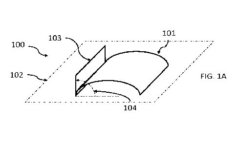
1171 Figure 1A illustrates an example cardboard support element 100 according
to this
disclosure. Support element 100 comprises a cardboard structure 101 extending
away from a base
plane 102. While base plane 102 may correspond for example to a panel such as
a panel of the
container, the base plane 102 may be a theoretical or virtual surface
permitting describing the
5 shape of the support element according to this disclosure. By extending
away from the base
plane, it should be understood that the cardboard structure comprises support
parts coinciding
with the base plane and at least a part extending away from the support parts,
the cardboard
structure developing a three dimensional shape, the cardboard material of the
cardboard structure
defining some boundaries of this three dimensional shape. In some examples the
cardboard
structure comprises a part separated from the base plane by at least 5 mm. In
some examples the
cardboard structure comprises a part separated from the base plane by at least
10 mm. In some
examples the cardboard structure comprises a part separated from the base
plane by at least 15
mm. In some examples the cardboard structure comprises a part separated from
the base plane by
at least 20 mm. In some examples the cardboard structure comprises a part
separated from the
base plane by at least 30 mm. In some examples the cardboard structure
comprises a part
separated from the base plane by at least 35 mm. In some examples the
cardboard structure
comprises a part separated from the base plane by less than 10 cm, for example
to avoid a
cantilever situation when the support element is acting as such. In some
examples, the three
dimensional shape is a portion of the cylinder or a portion of a prism. In the
example illustrated
in Figure 1A, the cardboard structure 101 corresponds to a portion of a
cylinder. As illustrated in
Figure 1A the cylinder has a cross section and an axis. In the example
illustrated in Figure 1A,
cardboard structure 101 is formed of a single cardboard sheet. The arcuate
shape taken by
cardboard structure 101 may be due to the cardboard structure being tensed
between other
elements, such other elements being part of the support element or being part
of a structure, such
as a lid, different from the support element and in which the support element
is located.
Cardboard support element 100 comprises a first flap 103. First flap 103 may
be a single flap of
the cardboard support element or the cardboard element may comprise other
flaps. A flap should
be understood as a piece of cardboard connected to the cardboard structure. A
flap may be
connected to the cardboard structure by a folding line, in which case the
support element may be
made of an integral cardboard piece. The flap may be connected to the
cardboard structure by a
segment, for example the folding line, which is parallel to an axis of the
cylinder or prism
corresponding to the cardboard structure, the axis of the cylinder or prism
being parallel to the
base plan. A flap may be connected to the cardboard structure by glue. A flap
may be integral to
the cardboard structure or be a separate piece from the cardboard structure,
while being
CA 03181308 2022- 12- 2
WO 2022/011199 PC
T/US2021/040979
6
connected to the cardboard structure to form the support element. The flap
according to this
disclosure extends in a direction normal to the base plane. Normal or
perpendicular should be
understood in this description as substantially normal or substantially
perpendicular. In some
examples, normal or perpendicular comprises angles of less than 120 and of
more than 60
degrees. In some examples, normal or perpendicular comprises angles of less
than 110 and of
more than 70 degrees In some examples, normal or perpendicular comprises
angles of less than
110 and of more than 70 degrees. In some examples, normal or perpendicular
comprises angles
of less than 100 and of more than 80 degrees In some examples, normal or
perpendicular
comprises angles of less than 95 and of more than 85 degrees. First flap 103
makes for example
an angle 104 of 90 degrees with base plane 102.
[18] The cardboard support element according to this disclosure is aimed at
providing
mechanical support for a cardboard wall, for example a cardboard wall of a
container or of a lid
of a container, such cardboard wall lying against the support element if
submitted to a force or to
a pressure.
[19] Figure 1B illustrates another example cardboard support element 110
comprising a
cardboard structure 111 extending away from a base plane 112 and a first flap
113 connected to
the cardboard structure 111, the first flap 113 being extended in a direction
normal to the base
plane 112. In this example of Figure 1B, the cardboard structure corresponds
to portion of a
prism, more specifically a triangular prism when taking the base plane 112
into account. In this
example, the support element comprises a second flap 115, the second flap 115
being in this
example connected to the cardboard structure 111 and extended in a direction
parallel to the base
plane, in this example coinciding with the base plane. In this example, the
cardboard structure
111 comprises a first primary panel 116 and a second primary panel 117
connected by a linear
ridge 118, the first primary panel 116 and the second primary panel 117
respectively
corresponding to a first face and a second face of a prism, the ridge 118
corresponding to an edge
of the prism connecting the first and the second face, the first 116 and
second 117 primary panels
preferably making an angle of more than 15 degrees with the base plane. In
this case, the primary
panel makes an angle 116 of about 30 degrees with the base plane. In this
example, the first flap
113 is directly connected to the first primary panel 116 and the second flap
115 is directly
connected to the second primary panel 117. In some examples the ridge is
separated from the
base plane by at least 5 mm. In some examples the ridge is separated from the
base plane by at
least 10 mm. In some examples the ridge is separated from the base plane by at
least 15 mm. In
CA 03181308 2022- 12- 2
WO 2022/011199 PC T/US2021
/040979
7
some examples the ridge is separated from the base plane by at least 20 mm. In
some examples
the ridge is separated from the base plane by at least 30 mm. In some examples
the ridge is
separated from the base plane by at least 35 mm. In some examples the ridge is
separated from
the base plane by less than 10 cm, for example to avoid a cantilever situation
when the support
element is acting as such.
[20] Figure IC illustrates another example cardboard support element 120
comprising a
cardboard structure 121 extending away from a base plane 122 and a single
first flap 123
connected to the cardboard structure 121, the first flap 123 being extended in
a direction normal
to the base plane 122. In this example of Figure 1C, the cardboard structure
corresponds to
portion of a prism, more specifically a tetragonal prism when taking the base
plane 122 into
account.
[21] Figure ID illustrates another example cardboard support element 130
comprising a
cardboard structure 131 extending away from a base plane 132 and a first flap
133 connected to
the cardboard structure 131, the first flap 133 being extended in a direction
normal to the base
plane 132. In this example of Figure 1D, the cardboard stnicture corresponds
to portion of a
prism, more specifically a pentagonal prism when taking the base plane 132
into account In this
example, the support element comprises a second flap 135, the second flap 135
being in this
example connected to the cardboard structure 131 and extended in a direction
normal to the base
plane. In this example, the cardboard structure 131 comprises a first primary
panel 136 and a
second primary panel 137 connected by a linear ridge 138, the first primary
panel 136 and the
second primary panel 137 respectively corresponding to a first face and a
second face of a prism,
the ridge 138 corresponding to an edge of the prism connecting the first and
the second face. In
this example the support element further comprising a first secondary panel
139 and a second
secondary panel 140, the first secondary panel 139 connecting the first flap
133 and the first
primary panel 136, the second secondary panel 140 connecting the second flap
135 and the
second primary panel 137, whereby fold lines separate the first flap 133 from
the first secondary
panel 139, the first secondary panel 139 from the first primary panel 136, the
first primary panel
136 from the second primary panel 137, the second primary panel 137 from the
second secondary
panel 140 and the second secondary panel 140 from the second flap 135, the
fold lines being
parallel to the linear ridge 138, which is itself parallel to the axis of the
prism. In this example,
the first flap 133 is indirectly connected to the first primary panel 136 by
way of the first
CA 03181308 2022- 12- 2
WO 2022/011199 PC T/US2021
/040979
8
secondary panel 139 and the second flap 135 is indirectly connected to the
second primary panel
137 by way of the second secondary panel 140.
[22] It should be understood that features such as number of flaps, flap
orientations, number of
panels and angles of various examples hereby described may be combined to
produce alternative
examples.
[23] Figure 2 illustrates yet another example cardboard support element 200
comprising a
cardboard structure 201 extending away from a base plane 202 and a first flap
203 connected to
the cardboard structure 201, the first flap 203 being extended in a direction
normal to the base
plane 202. In this example of Figure 2, the cardboard structure 201
corresponds to a portion of a
prism, more specifically a triangular prism when taking the base plane 202
into account. In this
example, the support element comprises a second flap 205, the second flap 205
being in this
example connected to the cardboard structure 201 and extended in a direction
normal to the base
plane 202. In this example, the cardboard structure 201 comprises a first
primary panel 206 and a
second primary panel 207 connected by a linear ridge 208, the first primary
panel 206 and the
second primary panel 207 respectively corresponding to a first face and a
second face of a prism,
the ridge 208 corresponding to an edge of the prism connecting the first and
the second face. In
this example the support element further comprising a first secondary panel
209 and a second
secondary panel 210, the first secondary panel 209 indirectly connecting the
first flap 203 and the
first primary panel 206, the second secondary panel 210 indirectly connecting
the second flap
205 and the second primary panel 207. In this example, the support element 200
further
comprising a first tertiary panel 211 and a second tertiary panel 212, the
first tertiary panel 211
directly connecting the first flap 203 and the first secondary panel 209, the
second tertiary panel
212 connecting the second flap 205 and the second secondary panel 210, whereby
fold lines
separate the first flap 203 from the first tertiary panel 211, the first
tertiary panel 211 from the
first secondary panel 209, the first secondary panel 209 from the first
primary panel 206, the first
primary panel 206 from the second primary panel 207, the second primary panel
207 from the
second secondary panel 210, the second secondary panel 210 from the second
tertiary panel 212
and the second tertiary panel 212 from the second flap 205, the fold lines
being parallel to the
linear ridge 208, whereby the first and second secondary panels each make an
angle comptised
between 0 and 10 degrees with the base plane and whereby the first and second
tertiary panels
preferably each make an angle of more than 15 degrees with the base plane. In
this specific
CA 03181308 2022- 12- 2
WO 2022/011199 PC
T/US2021/040979
9
example, the first secondary panel 209 and the second secondary panel 210 are
parallel to the
base plane 202.
[24] Figure 3 illustrates a lid 300 for a cardboard container comprising a
detergent product, the
lid 300 comprising a support element. While the support element may be any
support element
according to this description, the lid 300 is here illustrated with support
element 200 illustrated in
Figure 2. Lid 300 is illustrated upside down in order to clearly visualize
support element 200. In
this example, the lid is illustrated as comprising a single support element
according to this
disclosure. A lid according to this disclosure may however comprise one or
more additional
supports. Using one or more additional support elements may permit saving
material while
obtaining the effect of a support element on different sides of a lid. Using a
single support
element may permit compensating opposed forces on opposed sides of a lid on
the single support
element. In a preferred embodiment, a single support is used, use of a single
support reducing
manufacturing complexity. In another preferred embodiment, two support
elements are used on a
single lid, such two support element being placed against opposite flanks,
such two support
elements being substantially parallel to each other, such two support element
having respective
apex which may be aligned or which may correspond to different relative
positions, such
respective apex being preferably aligned to correspond to positions of fingers
of a consumer
gripping the lid. The use of two support elements has the advantage of
enabling use of less
material than for a single support element, whereby the two support elements
may be separated
by a gap between the two support elements.
[25] The lid 300 comprises a top 301 (here illustrated at the bottom due to
the lid being upside
down to offer a good vision of the support element) and flanks 302-305, the
top 301 being
parallel to the base plane 202, the first flap 203 being affixed to a first
flank 302 of the flanks, the
support element 200 comprising a second flap 205 connected to the cardboard
structure 201 and
extended in a direction normal to the base plane 202 The second flap may also
be parallel to the
base plane 202. The second flap is affixed to a second flank of the flanks,
the first flank being
opposite to the second flank. The second flap may alternatively be affixed to
the top. In this and
other examples, one should note that when the lid is in the closed position
and placed on top of
the container, sidevvalls of the container would be inserted against the first
flap and thereby
participate to rigidity of the entire assembly formed by the container closed
by the lid.
CA 03181308 2022- 12- 2
WO 2022/011199 PC T/US2021
/040979
1261 Figure 4 illustrates a consumer product 400 comprising a detergent
product (not
illustrated) and a container, the container comprising a box 401 and a lid
such as lid 300
comprising a support element according to this disclosure, the box 401
comprising a lock 402 to
maintain the lid 300 in a closed position, the lock 402 comprising an actuator
403 aligned with a
5 portion of the cardboard structure 201 when the lid 300 is in the closed
position, the cardboard
structure 201 fitting within the box 401 when the lid 300 is in the closed
position.
[27] Detergent products are products which may be relatively heavy, for
example when a
container for such product is carrying the full weight of such detergent
products, in particular
10 when the consumer product is recently acquired and thereby holds a
significant quantity of
detergent product. While some consumers may lift and transport such a consumer
product
holding a base of a box containing such detergent product, such lifting and
transport may also
occur by holding such consumer product by a lid, without holding the base. In
such cases, it is
possible that the lid, submitted to the force of gravity of the detergent
product, gets released and
opens the box, the box falling and possibly spreading its content. Such
situations should be
avoided. Beyond avoiding such unintentional lid unlocking, the structure of
the container of a
consumer product should preserve or improve opening ergonomics and prevent or
reduce a
permanent side wall deformation upon excessive or repetitive application of
forces applied to the
consumer product, for example during transport, in a grocery shopping bag
against other objects,
when submitted to external pressure, or when dropped. At the same time,
containers may be
elaborated in order to preserve the environment. The consumer product
according to this
disclosure aims at taking these different aspects into account.
[28] A consumer product should in this disclosure be understood as a product
which is
provided, among others, to end consumers. Such consumer products may for
example be
available for purchase in supermarkets and end consumers may store such
consumer products in
their homes. Consumer products may be provided in large quantities and should
thereby be
designed taking environmental concerns into account. Consumer products should
also be
designed taking transportation to a retail store into account. Consumer
products should also be
designed taking on the shelf storage in a retail store into account. Consumer
products should also
be designed taking transportation from a 'retail stole to a consumer home into
account. Consumer
products should also be designed taking storage at a private end consumer home
into account.
Consumer products should also be designed taking use of the consumer product
at a private end
CA 03181308 2022- 12- 2
WO 2022/011199 PC T/US2021
/040979
11
consumer home into account. Consumer products should also be designed taking
disposal into
account.
[29] The consumer product according to this disclosure comprises a detergent
product.
Detergent products should be understood in this disclosure as products
comprising a surfactant.
Detergent products may also comprise a bleach or other ingredients. Example
detergent product
compositions are described in more detail herein. In some examples, the
detergent product
comprises unit dose detergent pouches, preferably water soluble unit dose
detergent pouches,
more preferably flexible water soluble unit dose detergent pouches. Example
unit dose detergent
pouches are described in more detail herein.
[30] The consumer product according to this disclosure further comprises a
container. A
container should be understood in this disclosure as an object housing a
content, for example in a
cavity of the container. The container facilitates protection, transport,
storage, access and
disposal of the consumer product. In this disclosure, the container comprises
a box. A box should
be understood as a generally parallelepiped, barrel shaped, cylindrical,
round, oval or cubical
three dimensional object defining a cavity. The use of parallelepiped boxes
may facilitate storage
and transportation by permitting piling up boxes in a space efficient manner.
In some examples, a
box may be a parallelepiped provided with some rounded, tapered trapezium or
chamfered edges.
The box according to this disclosure comprises the detergent product. It
should be understood
that the detergent product is contained or stored in the box. The box
according to this disclosure
may comprise a base, sidewalls and an opening. A base according to this
disclosure should be
understood as a surface on which the box may lie when placed on a supporting
surface such as a
shelf or a floor. In some examples, the base is flat. In some examples, the
base is rectangular. In
some examples, the base is oval or round. In some examples, the base is flat.
In some examples,
the base has an embossed profile standing in or out in relief The sidewalls
according to this
disclosure should be understood as extending from the base, and connecting the
base to the
opening, to a transition piece or to the lid. It should be understood that the
connection of the base
to the opening may include a transition piece in addition to a sidewall. A
transition piece may be
glued or otherwise attached to the sidewall for example. In some examples, the
sidewalls are
perpendicular to the base. In some examples, the base is rectangular and has
four sides, four
sidewalls extending perpendicular from the base, each sidewall being
rectangular, each side wall
being connected by a sidewall side to a side of the base, and by two other
sidewall sides to two
other of the four sidewalls. In some examples the base is oval or circular and
the sidewalls form a
generally cylindrical wall extending from the base in a direction normal or
perpendicular to the
CA 03181308 2022- 12- 2
WO 2022/011199 PC T/US2021
/040979
12
base. In some examples, sidewalls have a shape corresponding to one of a
square, a rectangle, a
trapeze, a section of a sphere, a section of an ovoid, or a section of an
ellipsoid. The opening
according to this disclosure should be understood as an aperture providing
access to the detergent
product comprised in the box. In some examples, the opening faces the base. In
some examples,
the opening has a surface of less than the surface of the base. In some
examples, the opening has
a surface larger than the surface of the base in order to provide an improved
access, for example
using sidewalls extending from the base at angle of more than 90 degrees from
the base. In some
examples, the opening is provided after removal of a tamper proof feature, for
example
comprising a perforated piece to be removed at first use or a tamper evident
sticker locking the
lid to the box or tray. In some examples, the opening is placed on a top panel
of the box, the top
panel of the box facing the base of the box, the top panel of the box being
separated from the
base of the box by at least the sidewalls, the top panel of the box being
generally coplanar with
the base of the box, whereby the opening covers a portion of the top panel,
the top panel
comprising a peripheral section surrounding the opening, the peripheral
section being a transition
piece between a sidewall and the opening for example. In some examples, the
opening is
rectangular. In some examples, the opening is rectangular with rounded edges.
In some
examples, the opening is round or oval. the lid according to this disclosure
should be understood
as an element permitting to repeatedly close or open the opening of the
container. In some
examples the lid may be connected to the box, for example by a hinge, or may
be separated from
the box. The lid according to this disclosure may comprise a top and flanks.
It should be
understood that the top of the lid is aimed at covering the opening of the box
when the lid is in a
closed position. In some examples, the top of the lid is rectangular. In some
examples the top of
the lid is round, hexagonal, octagonal, or oval. In some examples, the lid
comprises beveled
edges. In some examples, the top of the lid is rectangular with rounded edges.
It should be
understood that while being named "top", the top of the lid may be positioned
in different
orientations. The lid may comprise flanks. It should be understood that the
flanks according to
this disclosure are elements connected to the top of the lid and extending
from the lid in order to
engage one or more sidewalls of the box. The flanks participate in placing the
top of the lid onto
the opening. In some examples, the flanks extend perpendicularly from the top
of the lid. In some
examples, the flanks surround an entire perimeter of the top of the lid. In
some examples, the
flanks partially surround an endue perimeter of the top of the lid, a portion
of the top of the lid
being flankless. The top of the lid may cover the opening, and at least a
portion of the flanks may
cover at least a specific portion of the sidewalls when the lid is in the
closed position, the lid
being moveable from the closed position to an open position. Movement of the
lid may be
CA 03181308 2022- 12- 2
WO 2022/011199 PC T/US2021
/040979
13
restrained by a connection to the box such as a hinge, or may be entirely
removable, for example
to provide an improved access to the content of the box. The box and lid
cooperate to participate
in fulfilling the role of the container to store, transport and facilitate
access to the content of the
container.
[31] The container according to this disclosure comprises a lock. A lock
should be in this
disclosure understood as a mechanism preventing or reducing the likelihood of
an accidental
opening. The lock according to this disclosure is to maintain the lid in a
closed position. It should
be understood that the lock according to this disclosure is expected to
function under normal use
of the container. It should be understood that the lock may not fulfill its
function when for
example unusual use is made of the box, or when the box is under unusual
conditions. According
to this disclosure, the lock comprises an actuator moveable from a locking
position to an opening
position by applying an actuation pressure onto the actuator when the lid is
in the closed position.
The actuator should be understood in this disclosure as a mechanical structure
submitted to a
movement upon actuation by an outside force or actuation pressure, such
movement leading to
the opening of the lock when such movement takes place. In some examples, the
actuator
according to this disclosure is resilient and has a default position, such
default position
corresponding to the lid remaining closed, the resilience being vanquished by
an outside force or
actuation pressure in order to open the lid. In some examples, the actuator is
resilient in that the
actuator comprises a flexible element, the flexible element having a default
position
corresponding to the lid remaining closed, the flexible element being pressed
to open the lid, the
flexible element springing back to the default position when releasing
pressure. It should be
understood that a pressure is generated by the application of a force onto a
surface. The actuator
according to this disclosure has at least two positions being an opening
position and a locking
position, whereby the opening position corresponds to a position permitting
opening of the lid,
the locking position preventing opening of the lid or reducing the possibility
of an accidental
opening of the lid.
[32] The actuator according to this disclosure is may be connected to a
specific portion of
sidewalls of the box, which may be a specific portion covered by at least a
portion of the flanks
when the lid is in the closed position, the actuator abutting against a
locking tab of the flanks
when in the locking position, the actuator being maintained away from the
locking tab when in
the opening position, the actuator being displaceable by the actuation
pressure by an unlocking
displacement distance in a direction normal to the specific portion of the
sidewalls. The
CA 03181308 2022- 12- 2
WO 2022/011199 PC T/US2021
/040979
14
connection of the actuator to the specific portion of the sidewall is due to
the actuator
participating in locking or unlocking the specific portion of the sidewall
from the portion of the
flanks covering the specific portion of the sidewall, thereby permitting
releasing the lid from the
box. The flanks may comprise a locking tab. A locking tab should be understood
as a mechanical
element which interlocks with the actuator. In some examples the locking tab
extends away from
the flanks and may be in the form of a bulge, a ridge, an embossment or an
additional material
layer sticking out of the flanks of the lid and towards the specific portion
of the side wall such
that the actuator may abut against the tab when in the locking position to
prevent separating the
specific portion of the sidewalls from the flank in the area of the actuator.
In some examples, the
locking tab is comprised in the flank itself, the locking tab being for
example formed by an
aperture in the flanks. Abutment according to this disclosure should be
understood as a contact
between the actuator or part of the actuator and the tab, such contact
preventing opening of the
lid. The actuator is maintained away from the locking tab when in the opening
position, in order
to release the locking tab. Such release of the locking tab permits opening
the lid. Displacement
or movement of the actuator from the locking to the opening position is by
application on the
actuator (directly or indirectly) of an actuation pressure or force such that
the actuator is
displaced by a distance sufficient to supress contact of the actuator with the
locking tab, such
distance corresponding to the displacement distance, in a direction normal to
the specific portion
of the side wall. It should be understood that the force or pressure leading
to the displacement
may have a number of different directions, such different directions
contributing to the
displacement if a component of such force or pressure is in a direction normal
to the specific
portion of the side wall. Such force or pressure may also comprise a component
which may be
parallel to the side wall. The actuation is however triggered by a component
of such force or
pressure being normal to the portion of the side wall. Such presence of a
component normal to
the portion of the sidewall participates in the role of the lock of avoiding
an accidental opening
by lifting the container through lifting the lid by applying a force parallel
to the sidewall, whereas
desired opening would take place by the consumer "pushing" the actuator and
apply the
unlocking force or pressure permitting opening of the lid. In other words,
while a consumer may
apply a force on the actuator along a direction which may not be normal to the
sidewall, if a
component of such force is normal to the sidewall such component may
participate in applying
the pressure leading to the displacement.
[33] Such a lock would participate in suppressing or reducing the
risk of accidental opening of
the lid while permitting desired opening by a consumer, the functioning of
such a lock depending
CA 03181308 2022- 12- 2
WO 2022/011199 PC T/US2021
/040979
on ensuring that the actuator maintains abutting against the locking tab even
in case of pulling
strongly on the lid in a direction parallel to the side wall in order to
transport or lift the consumer
product. The avoidance or reduction of the risk of accidental opening would
also apply to a force
being applied in a direction parallel to the sidewalls for example by friction
with another box
5 located side to side with a box according to this disclosure, or by a box
falling over during
transportation, or by internal movements of the content of the box pushing the
lid during
transportation. Strong pulling in a direction parallel to the sidewall may
however impact the
structure of the sidewall, for example resulting in bending of the side wall,
whereby such bending
may produce undesired disengagement of the locking tab from the activator, due
to the fact that
10 the actuator is connected to the specific portion of the sidewall. This
would lead to an undesired
opening of the lid. Such undesired opening of the lid may be more likely if
the sidewall is made
of a material such as cardboard used to form the sidewalls, in particular when
the box is a
cardboard box.
15 [34] In some examples, the lock is placed in a central area of a
sidewall of the box. A central
area should be understood as substantially equidistant from opposite edges of
the sidewall
concerned, such edges being along a direction normal to the base of the box In
such examples, it
should be understood that the lock is located closest to an edge of the
sidewall close to the
opening than to an edge of the sidewall close to the base, while being in a
central area in respect
to the edges normal to the base. Such central location of the lock may
participate in avoiding
sliding of the lid from the box if the box is lifted by holding the lid by
applying pressure onto the
actuator, whereby such pressure presses the actuator against the support
element centrally,
thereby balancing the forces maintaining the connection between the lid and
the box and
participating in avoiding accidental opening. In some examples, the lock may
be located on a
sidewall and between two edges of the sidewall, such edges being normal to the
base, the lock
being closer to one edge than to the other edge of the two edges, for example
located closer to the
one edge at a 1/3 of the distance between the two edges. In some examples one
sidewall may
comprise two locks.
[35] The present disclosure aims at resolving this apparent contradiction
between, on one
hand, the use of materials for the sidewalls which would resist accidental
opening, and the use of
materials for the sidewalls which are particularly environmentally friendly.
[36] The container may be made from rigid cardboard material, flexible
cardboard material or
a mixture thereof In some example, the material forming the box or the lid has
a wall thickness
CA 03181308 2022- 12- 2
WO 2022/011199 PC T/US2021
/040979
16
of more than 300 microns and of less than 3mm. In some example, the material
forming the box
or the lid has a wall thickness of more than lmm and of less than 2mm. In some
example, the
material forming the box or the lid is folded on itself, for example to
reinforce parts of or the
whole of the box or the lid. The container may be made from paper materials,
bio based material,
bamboo fibres, cellulose fibres, cellulose based or fibre based materials, or
a mixture thereof
The container may be made from materials comprising recycled materials, for
example recycled
cellulose fiber based materials.
[37] The lid according to this disclosure indeed further comprises a support
element, the
support element entering the opening when the lid is in the closed position,
at least part of the
specific portion of the sidewalls being located between the flanks and the
support element when
the lid is in the closed position, a clearance distance separating the
sidewalls from the support
element in a direction normal to the specific portion of the sidewalls when
the lid is in the closed
position and when no actuation pressure is applied, the clearance distance
being reduced to zero
by flexing of the specific portion of the sidewalls when the actuation
pressure is applied above a
pressure threshold when the lid is in the closed position. Both the support
element and the flanks
are structurally part of the lid, the support element and the flanks
permitting sandwiching the
specific portion of the sidewall, thereby preventing sinking in of the
specific portion of the
sidewall and undesired disengagement of the actuator from the locking tab. It
is important to take
note of the fact that in case of an actuation pressure being applied while
lifting the box through
the lid, the pressure applied will catch the sandwiched specific portion of
the sidewall against the
support element, thereby compensating a force of gravity which would otherwise
disconnect the
lid from the box, such compensation of the gravity force being through a
resisting static friction
force between the specific portion of the sidewall and the support element. In
some examples, the
use of the support element permits using for making the box a relatively
flexible material,
whereby such flexible material would flex in the absence of the support
element to the point that
the box would fall off if lifted by its lid Permitting using a relatively
flexible material also
permits using a lesser quantity of such material due to the presence of the
support element which
compensates for such flexibility. The presence of such support element thereby
prevents or
reduces the risk of accidental opening even if the actuation pressure is
applied onto the actuator
of the lock, for example as the box is lifted while applying pressure on the
actuator of the lock.
[38] The support element may in some example be made of the same material as a
material
used for making the top of the lid. In some examples the support element is
made of a material
different from the material used for the top of the lid. The support element
enters the opening
CA 03181308 2022- 12- 2
WO 2022/011199 PC
T/US2021/040979
17
when the lid is in the closed position. Such entering the opening should be
understood in that the
support element comprises a support element portion which enters the opening
when the lid is
moved from the open to the closed position, and whereby such support element
portion exits the
opening when the lid is moved from the closed to the open position. At least
part of the specific
portion of the sidewalls is located between the flanks and the support element
when the lid is in
the closed position. This structure permits capturing the specific portion of
the sidewall between
the flanks and the support element, the specific portion of the sidewall
getting inserted between
the flanks and the support element when the lid moves from the open to the
closed position, the
specific portion of the side wall being released from between the flanks and
the support element
when the lid moves from the closed to the open position. A clearance distance
separates the
sidewalls from the support element in a direction normal to the specific
portion of the sidewalls
when the lid is in the closed position, such direction corresponding for
example to a direction of
the linear ridge, and when no actuation pressure is applied Such clearance
distance would exist
on a first side, and be repeated additionally on a second side of the support
element. Such
clearance distance permits insertion of the support element through the
opening as the lid gets
closed, such that the support element does not collide with the specific
portion of the sidewall
when the lid gets closed. The clearance is reduced to zero by flexing of the
specific portion of the
sidewalls when the actuation pressure is applied above a pressure threshold
when the lid is in the
closed position. When such pressure threshold is reached, the sidewall lays
against the support
element through the clearance distance being reduced to zero, the sidewall
thereby being
prevented from being exceedingly distorted and being prevented from sinking in
to the point of
the actuator releasing the locking tab. The clearance distance according to
this disclosure relates
in some examples to a tolerance distance between the lid and the box which
both permits placing
the lid onto the box without undue difficulty, while avoiding that the lid be
loose when in the
closed position. While the clearance distance according to this disclosure is
considered in a
region of the lock, the tolerance distance between the lid and the box may be
considered along an
entire perimeter of the opening of the box. In some examples, the tolerance is
of at least 0.1 mm
and of less than 5 mm. In some examples the tolerance is of at least lmm and
of less than 3 mm
Such tolerance would for example be measured when the lid is in the closed
position and
between an internal surface of the flanks and an external surface of the
sidewalls, understanding
that such tolerance may take a different value in a region of the lock.
[39] In some examples, the clearance distance is of at least 1mm and of less
than 1cm when
the lid is in the closed position and no actuation pressure is applied. Such a
range permits both
easing the closing of the lid and preventing sinking of the specific portion
of the sidewall leading
CA 03181308 2022- 12- 2
WO 2022/011199 PC
T/US2021/040979
18
to undesired unlocking. In some examples, the clearance distance is of at
least 1.5mm and of less
than 0.5cm when the lid is in the closed position and no actuation pressure is
applied. In some
examples, the clearance distance is of at least 2mm and of less than 0.4cm
when the lid is in the
closed position and no actuation pressure is applied.
1401 In some examples, as for example illustrated in Figure 4, the actuator
comprises a flap
403 connected by a hinge portion to a specific portion of the sidewalls of the
box, the flap
extending from the hinge portion to a distal edge of the flap, the hinge
portion being located
between the flanks and the support element when the lid is in the closed
position, the distal edge
extending away from the specific portion of the sidewalls and the distal edge
of the flap abutting
against the locking tab of the flanks when in the locking position, the flap
lying flush against the
specific portion of the sidewalls and the distal edge being maintained away
from the locking tab
when in the opening position, the actuation pressure displacing the flap by an
acute actuation
angle from the closing position to the opening position, the acute angle
corresponding to
displacing the distal edge by the unlocking displacement distance. In some
examples, the acute
angle is between 5 and 60 degrees. In some examples, the acute angle is
between 5 and 45
degrees. In some examples, the acute angle is between 5 and 20 degrees. In
some examples the
acute angle is a function of the length of the locking flap in a direction
generally parallel to the
specific portion and of a thickness of the locking tab and of tolerances
between the sidewalls of
the box and the flanks of the lid and of a tolerance between the sidewalls of
the box and the flap,
or patch as disclosed below. In some examples horizontal displacement (along a
direction
substantially normal to a sidewall comprising the specific section) measured
at the end of the
locking flap abutting with the locking tab is of at least a thickness of the
locking tab along a
direction substantially normal to a sidewall comprising the specific section.
In some examples
such horizontal displacement is comprised between 0.3mm and 30mm. In some
examples a
length of the flap has a length along a direction generally normal to the base
of the box larger
than the sum of different tolerances comprising a play between the locking tab
and the flap in the
abutment area when the lid is in the closed position and the container is not
submitted to external
pressure, a tolerance between the flanks of the lid and the sidewalls of the
box, and the tolerance
between the side walls of the box and the flap and a bending deformation of
the flap. In some
examples the locking flap has a length along a direction generally normal to
the base of the box
of at least 3 mm and of less than 60mm In some examples the locking flap has a
length along a
direction generally normal to the base of the box of at least 15 mm and of
less than 45 mm. In
some examples the locking flap has a length along a direction generally normal
to the base of the
box of at least 25 mm and of less than 35 mm. In some examples, the flap has a
width along a
CA 03181308 2022- 12- 2
WO 2022/011199 PC T/US2021
/040979
19
direction perpendicular to its length and parallel to the specific portion of
between 5mm and
60mm. Such example width dimensions may permit easing disengaging the lock by
limiting its
width while avoiding a risk of the lock getting distorted by pressure by
providing the lock with a
sufficient width. Such dimensioning selection may be dependent on the material
selected for the
different parts forming the container. Such a flap may be used in examples or
configurations
differing from the ones illustrate in Figure 4.
[41] In some examples, not illustrated here, the actuator comprises a patch
glued to the
specific portion of the sidewalls. Such patch may for example be a piece of
material of the same
nature as a material used for the making of the box or of the lid, such piece
of material being for
example glued to the box, the piece of material being structurally separate
from the box, the piece
of material interacting with the locking tab, the piece of material comprising
for example a fold
line defining a first part interacting with the locking tab and a second part
glued to the box,
thereby functioning as the flap hereby described.
[42] In some examples such as illustrated in Figure 4, the support element 200
comprises a
support area, the support area comprising an area of contact with the specific
portion of the
sidewall when the clearance is reduced to zero by flexing of the specific
portion of the sidewalls
when the actuation pressure is applied above the pressure threshold when the
lid is in the closed
position, whereby the area of contact faces the actuator 403 along a direction
normal to the
specific portion of the side walls. Bringing such area of contact at the level
of the actuator
permits improving the resiliency of the structure, whereby the actuation
pressure will be directly
absorbed by the support element once the clearance distance which separates
the sidewalls from
the support element is reduced to zero and the actuator makes direct contact
with the support
element at the area of contact.
[43] The example consumer product 400 comprises a lock 402 as illustrated in
Figure 4. The
consumer product 400 also comprises an additional lock (not illustrated).
Indeed, in this example
and in some other examples, the consumer product comprises an additional lock,
the additional
lock comprising an additional actuator connected to an additional specific
portion of the
sidewalls, the specific portion of the sidewalls being comprised in a first
sidewall of the box, the
additional specific portion of the sidewalls being comprised in a second
sidewall of the box, the
first sidewall being opposite to the second sidewall. The consumer product 400
comprises
actuator 403 of the lock 402 and additional actuator of lock. It should be
understood that in this
example and in some other examples comprising an additional lock, such
additional lock may
CA 03181308 2022- 12- 2
WO 2022/011199 PC T/US2021
/040979
have a structure similar to or different from the lock according to this
disclosure. In some
examples, the additional lock has a structure corresponding to the structure
of the lock according
to this disclosure. In some examples, the additional lock has a structure
differing from the
structure of the lock according to this disclosure. In some examples, an
additional lock is
5 provided according to this disclosure on a same sidewall as the lock
according to this disclosure.
In some examples, an additional lock is provided on a sidewall adjacent to the
sidewall
comprising the lock.
[44] In the example illustrated in Figure 4, the flanks of the lid comprise an
actuation area 404
10 and an additional actuation area 405. Indeed, in this example and in
some other examples, the
flanks of the lid comprise an actuation area facing the actuator and
permitting displacing the
actuator from the closing position to the opening position by applying the
actuation pressure at
the actuation area when the lid is in the closed position, whereby the
actuation area comprises
one or more of an actuation aperture, an actuation flap, an actuation slit or
an actuation
15 membrane, whereby the actuation area further comprises a visual
indication indicating the
location of the actuation area. In the example illustrated in Figures 4 and
9A, the actuation areas
404 and 405 each comprise an actuation aperture. The visual indication may be
printed on an
external surface of the flanks and may comprise one or more arrows or one or
more areas printed
in a striking colour or a specific text providing instructions such as "push
here to open" for
20 example, or a combination of any of these indications.
[45] In the example illustrated in Figure 4 and in some other examples not
illustrated here, the
flanks comprise the additional actuation area 405 facing the additional
actuator and permitting
displacing the additional actuator, the actuation area 404 and the additional
actuation area 405
being separated by a peripheral path along an exterior surface of the lid, the
peripheral path
measuring less than 2D cm and more than 9 cm. In some examples, this
peripheral path is the
shortest peripheral path between a top of the actuation area and a top of the
additional actuation
area, such top being a point of the respective actuation area or additional
actuation area closest to
the top of the lid. In some examples, the peripheral path measures less than
15 cm and more than
11 cm. In some examples, the peripheral path measures less than 14 cm and more
than 12 cm.
The length of such peripheral path may advantageously permit an adult user to
apply a thumb of
one hand on the actuator and the index (or middle finger) of the same one hand
on the additional
actuator at the same time in order to press on both the actuator additional
and the additional
actuator simultaneously with one hand in order to unlock the lid and open the
lid. In other
CA 03181308 2022- 12- 2
WO 2022/011199 PC T/US2021
/040979
21
examples, two locks may be provided on a same sidewall, opening taking place
by actuating on
both locks, for examples using both thumbs.
[46] In the example consumer product 400, actuation areas 404 and 405 are
separated in a
straight line from the outside surface of the respective flanks where they are
located by a
distance, whereby such distance is of more than 6cm and of less than 12cm. In
some examples,
the distance is of about 8cm. In some examples, the distance is of more than
7.5 cm and of less
than 8.5 cm. In some examples, the distance is of more than 8.4 cm and of less
than 10.4 cm. In
some examples, the distance is of more than 8.9 cm and of less than 9.9 cm. In
some examples,
the distance is of about 9.4 cm. In some examples, the clearance distances
which separates the
sidewalls from the support element are each of between 1 mm and 4 mm when no
actuation
pressure is applied. In some examples, the clearance distances are each of
between 3mm and 4
mm when no actuation pressure is applied.
[47] In the example illustrated in Figure 4, each lock is separated from a
respective gable of
the support element by a clearance distance. In this example and in some other
examples
according to this disclosure, the support element comprises a resilient
structure concurrently in
contact with both the specific portion and the additional specific portion
when flexing of both the
specific portion of the first sidewall and the additional specific portion of
the second sidewall
when the actuation pressure is applied above the pressure threshold on both
the actuator and the
additional actuator when the lid is in the closed position In such a
configuration the resilient
structure of the actuator absorbs any excess pressure applied onto the
actuators in order to open
the lid. In some examples, the resilient structure, or cardboard structure, is
unitary, for example to
facilitate manufacturing. Unitary should be understood as being made from an
integral piece of
material. In some examples, the resilient structure comprises a plurality of
substructures, for
example to facilitate assembly.
[48] In some examples the flanks of the lid cover about 30% of the sidewalls
of the box, 30%
corresponding in this case to a ratio between on one hand a height of the
flanks in a direction
normal to both the top of the lid and the base of the box and on the other
hand the height of the
sidewalls in the direction normal to both the top of the lid and the base of
the box. In an example,
the flanks completely surround the sidewalls around the opening. Such coverage
of the flanks
participates in ensuring lid placement, structural resiliency and protection
of the content. In some
examples, the flanks cover at least 30% of the sidewalls when the lid is in
the closed position. In
some examples, the flanks cover at least 35% of the sidewalls when the lid is
in the closed
CA 03181308 2022- 12- 2
WO 2022/011199 PC T/US2021
/040979
22
position. In some examples, the flanks cover at least 40% of the sidewalls
when the lid is in the
closed position. In some examples, the flanks cover at most 90% of the
sidewalls when the lid is
in the closed position. In some examples, the flanks cover at most 80% of the
sidewalls when the
lid is in the closed position. In some examples, the flanks cover at most 70%
of the sidewalls
when the lid is in the closed position. In some examples, a manufacturing
process comprises
providing different box sizes, for example boxes having a sidewall height of
either 10cm, 11.5
cm, 13.5 cm or 16cm, whereby each box may be provided with a same lid fitting
all box sizes
provided, such as a lid having a flank height of 7 cm In some examples, flank
height is of more
than 3cm. In some examples, flank height is of more than 5cm. In some
examples, flank height is
of more than 6cm.
[49] Figure 5 illustrates an example planar support element blank 500 for a
support element
according to this disclosure, in this case corresponding to support element
300. The blank 500
comprising a first flap 203, a first primary panel 206, a second primary panel
207, and a second
flap 205 following each other in this order, each flap or panel being
separated from the next by at
least a fold line, the fold lines 213 being along a same linear direction. In
this specific example,
the blank also comprises a first secondary panel 209 and a second secondary
panel 210 such that
the first flap 203, the first secondary panel 209, the first primary panel
206, the second primary
panel 207, the second secondary panel 210 and the second flap 205 follow each
other in this
order. In this example, the blank also comprises a first tertiary panel 211
and a second tertiary
panel 212, such that the first flap 203, the first tertiary panel 211, the
first secondary panel 209,
the first primary panel 206, the second primary panel 207, the second
secondary panel 210, the
second tertiary panel 212 and the second flap 205 follow each other in this
order. While the blank
represented in Figure 5 corresponds to the support element 200 for
illustrative purposes, other
blanks may correspond to other examples, comprising panels and fold lines
corresponding to the
respective support elements.
[50] Figure 6 illustrates an example planar support element blank 600 for a
support element
according to this disclosure, in this case similar to support element 300 The
blank 600
comprising a first flap 603, a first primary panel 606, a second primary panel
607, and a second
flap 605 following each other in this order, each flap or panel being
separated from the next by at
least a fold line, the fold lines 613 being along a same linear direction_ In
this specific example,
the blank also comprises a first secondary panel 609 and a second secondary
panel 610 such that
the first flap 603, the first secondary panel 609, the first primary panel
606, the second primary
panel 607, the second secondary panel 610 and the second flap 605 follow each
other in this
CA 03181308 2022- 12- 2
WO 2022/011199 PC T/US2021
/040979
23
order. In this example, the blank also comprises a first tertiary panel 611
and a second tertiary
panel 612, such that the first flap 603, the first tertiary panel 611, the
first secondary panel 609,
the first primary panel 606, the second primary panel 607, the second
secondary panel 610, the
second tertiary panel 612 and the second flap 605 follow each other in this
order. In this example,
the first primary panel 606 and the second primary panel 607 have a first
maximal width along a
direction parallel to the linear ridge and the first flap 603 has a second
maximal width along the
direction parallel to the linear ridge, whereby the second maximal width is of
less than 90% of
the first maximal width This configuration permits saving material while
maintaining the
function of the support element provided by the cardboard structure. In this
example, the first and
second flaps have chamfered edges which also participate in saving material.
[51] In some examples, one or more panels such as the primary, secondary, or
tertiary first or
second panels have a width along a direction parallel to the linear ridge
which varies, for
example in order to accommodate for different shapes of lids, or for saying an
amount of
materials used, while maintaining the support function of the cardboard
support element.
[52] Figure 7 illustrates an example planar blank assembly 700 comprising the
support
element blank according to this disclosure, in this case support element blank
500 illustrated in
Figure 5, and a lid blank 701, the lid blank comprising a first flank flap
702, a second flank flap
703 and a top panel 704 between the first flank flap 702 and the second flank
flap 703, whereby
the first flap 503 is affixed to first flank flap 702, whereby the first
primary panel 506 and the
second primary panel 507 rest freely on the top panel 704 and whereby the
second flap 505 is
affixed to the second flank flap 703. In other examples, the second flap 505
is affixed to the top
panel 704. The support element blank may comprise other panels, as for example
this support
element blank 500 described in Figure 5. The lid blank also may comprise other
panels or flaps
beyond the ones illustrated here.
[53] Figure 8 illustrates an example method to erect a cardboard structure and
a lid according
to this disclosure from a planar blank assembly according to this disclosure,
in this case planar
blank assembly 700, the method comprising folding the first flank flap 702 to
form a flank of the
lid, the folding of the first flank flap 702 producing the erecting of the
cardboard structure away
from the top panel in a direction parallel to a direction of the folded flank
to form the support
element according to this disclosure. In this example, the second flank flap
703 is also folded to
participate in erecting the lid according to this disclosure. In this example,
the first flap 503 is
affixed to the first flank flap 702 by glue 705. In this example, the second
flap 505 is affixed to
CA 03181308 2022- 12- 2
WO 2022/011199 PC
T/US2021/040979
24
the second flank flap 703 by glue 706. In another example, the second flap may
be glued to the
top panel of the lid, in which case the cardboard structure may be erected
solely by folding of the
first flap
[54] The fact that the primary panels of the support element blank rest freely
on the top panel
of the lid blank, and the fact that the first and second flaps are affixed,
wherein at least one of the
first and second flaps are affixed to a flank flap of the lid, lead to
erecting the cardboard structure
as per this disclosure. This configuration permits providing a flat planar
blank assembly as per
this disclosure onto a manufacturing line, the flat planar assembly leading to
erecting a lid using
a reduced number of actions through the folding of the flanks of the lid. The
folding of the flanks
of the lid indeed lead to erecting both the lid flanks and the cardboard
structure of the support
element at the same time due to the affixing of the first and second flaps,
wherein at least one of
the first and second flaps are affixed to a flank flap of the lid, and due to
the first and second
primary panels resting freely onto the top panel and thereby moved away from
the top panel by
the folding action. While this is illustrated using a specific blank
structure, a same effect may be
obtained using other blank structures according to this disclosure. In order
to permit the erecting,
panels such as, for example, secondary or tertiary panels, situated between
the first and second
flaps should also rest freely on the top panel in order to slide into place
naturally. The support
element structure fold lines may be configured to form the support element as
desired, for
example by folding in one sense or in another sense. In some examples, when a
first and
secondary panel are provided, the first secondary panel and the second
secondary panel each
comprise at least one reinforcing element in order to maintain a planar
configuration of each of
the first secondary panel and the second secondary panel and to contribute to
erecting the
cardboard structure. Other examples comprise secondary panels without such
reinforcing
elements. Other panels or flaps may comprise reinforcing elements.
1551 As illustrated in Figure 8, the tertiary panels may push the secondary
panels resting flush
against the top panel, leading to the raising of the primary panels. In this
configuration, the first
and second flaps are separated from the tertiary panels by fold lines which
are at a distance 801
from the base plane, such distance forming a triangular space 802, 803 formed
by each tertiary
panel, a portion of the respective flank flap of the lid and by a portion of
the top panel.
[56] Figure 9A illustrates a planar blank assembly 900 according to this
disclosure. It is
important to note that a planar blank assembly according to this disclosure
greatly eases
transportation in a stack formed by a plurality of such planar blank
assemblies piled onto each
CA 03181308 2022- 12- 2
WO 2022/011199 PC T/US2021
/040979
other, whereby the blank of the lid is flush with the blank of the cardboard
support element for
each planar blank assemblies of the stack, whereby no elements "stick out"
from the planar blank
assembly, enabling shipment in a stable, efficient and cost effective manner,
lowering a risk of
damaging the planar assemblies. The planar blank assembly 900 comprises the
support element
5 blank 500 illustrated in Figure 5, and a lid blank 901, the lid blank 901
comprising a first flank
flap 902, a second flank flap 903 and a top panel 904 between the first flank
flap 902 and the
second flank flap 903, whereby the first flap 503 is affixed by glue 905 to
first flank flap 902,
whereby the first primary panel 506 and the second primary panel 507 rest
freely on the top panel
904 and whereby the second flap 505 is affixed by glue 906 to the second flank
flap 903. Lid
10 blank 901 further comprises panels and flaps permitting forming four lid
flanks, whereby the first
flank flap 902 and the second flank flap 903 form two opposite short lid
flanks, and panels 907
and 908 form two opposite long lid flanks. In this example, each long lid
flank corresponding to
panels 907 and 908 comprises a reinforced flank section 909 and 910. In some
examples, such
reinforced flank section comprises a main layer and an additional layer for
reinforcement. In
15 some examples, such reinforced flank section comprises a back folded
additional layer. In some
examples, such additional layer is glued to a main layer of the flanks. In
some examples, either
one of or both the box and the lid comprise a reinforcement area. Such
reinforcement area may
for example comprise a bended or folded back area Such reinforcement area may
for example
comprise an additional glued material or layer. Such reinforcement area may
comprise an insert
20 or a sleeve. In some examples the reinforcement area covers specific
areas of the box or lid. In
some examples, the reinforcement area comprises the box base. In some
examples, the
reinforcement area comprises the sidewalls In some examples, the reinforcement
area comprises
the flanks of the lid. In some examples, all areas of the box are reinforced.
In some examples, all
areas of the lid are reinforced. In some examples, the reinforced flank
section comprises the
25 locking tab. In some examples the reinforced flank section comprises a
main flank section and a
folded back flank section lying flush against the main flank section, the main
flank section being
hingedly connected to the folded back flank section at an end of the
reinforced flank section
distal from the top of the lid. Such flank reinforcement may contribute to
reinforcing the structure
of the closed container. The use of flank reinforcement, in particular of
flank reinforcement
which are folded back in a planar blank assembly according to this disclosure,
permit having a
same or similar thickness of the planar blank assembly at edges of the planar
blank assembly (by
way of the double thickness formed by the flank reinforcements) and towards
the centre of the
planar blank assembly (by way of the support element blank), such same or
similar thickness of
CA 03181308 2022- 12- 2
WO 2022/011199 PC T/US2021
/040979
26
the planar blank assembly permitting obtaining a stable stack of such planar
blank assembly for
transportation to a manufacturing facility.
[57] Figure 9B illustrates an example stack 911 of a plurality of planar blank
assemblies
according to this disclosure, whereby each lid blank comprises a folded back
flank section. In the
illustrated example, each planar blank assembly of the stack 911 is seen along
a direction
illustrated by direction V of Figure 9A. Stack 911 comprises 7 planar blank
assemblies according
to this disclosure. A stack may comprise more than 10 planar blank assemblies.
A stack may
comprise more than 20 planar blank assemblies. A stack may comprise more than
50 planar
blank assemblies. A stack may comprise more than 70 planar blank assemblies. A
stack may
comprise more than 100 planar blank assemblies. A stack may comprise more than
150 planar
blank assemblies. In this example, each planar blank assembly comprises a
folded back flank
section 910 and a folded back flank section 909 for flank reinforcement and a
planar support
element blank such as planar support element blank 500, as well as panels of
the lid such as, for
example, second flank flap 903, on which the planar support element blank and
folded back flank
sections lie flush. This forms a stable stack structure for transportation. In
this example, a
thickness of the planar support element blank is substantially equal to a
thickness of folded back
flank sections.
[58] Figure 10 illustrates a method to erect a lid from a planar blank
assembly according to
this disclosure, in this case from planar blank assembly 900 of Figure 9A. As
illustrated, the
method comprises folding the first flank flap 902 to form a flank of the lid,
the folding of the first
flank flap 902 producing the erecting of the cardboard structure away from the
top panel 904 in a
direction parallel to a direction of the folded flank to form the support
element according to this
disclosure.
[59] The lid obtained using planar blank assembly 900 corresponds to the
lid 300 illustrated in
Figure 4 of consumer product 400. Consumer product 400 comprises a support
element which
enters the opening with a shape having a triangular cross section in a plane,
reproducing a shape
similar to an inverted gable roof
[60] Example support elements according to this disclosure may be described
using
vocabulary used in roof types. Example support elements according to this
disclosure may
comprise a cardboard structure forming an open gable shape, the open gable
shape comprising a
first and second primary panels and a ridge between the first and second
primary panels.
CA 03181308 2022- 12- 2
WO 2022/011199 PC T/US2021
/040979
27
Example support elements according to this disclosure may comprise a cardboard
structure
forming a gambrel shape, the gambrel shape comprising a first and second
primary panels, a first
and second secondary panel, and a ridge between the first and second primary
panels Example
support elements according to this disclosure may comprise a cardboard
structure forming a
saltbox shape, the saltbox shape comprising a first and second primary panels
and a ridge
between the first and second primary panels.
[61] In some examples, the linear ridge is a line of symmetry of the cardboard
structure or of
the support element. This is the case for example of the support element
formed by blanks 500 or
600. This is particularly suitable in cases of a lid comprising an actuator or
actuation area located
in a centre of a flank, whereby such lid may be placed in one sense or in
another sense while
remaining functional due to its symmetrical structure. In other words, and
referring for example
to Figure 4, while actuation area 404 is aligned to correspond to actuator
403, the lid 300 is
reversible and actuation 405 could be made to correspond to actuator 403 by
placing the lid in a
symmetrical manner.
[62] The support element as per this disclosure may comprise a support element
distal end
located when the lid is in the closed position at a certain depth. In some
examples, the depth is of
at least 3mm and of less than 50 mm from the top of the lid. In some examples,
the depth is of at
least 5 mm and of less than 50 mm from the top of the lid. In some examples,
the depth is of at
least 15 mm and of less than 40 mm from the top of the lid. In some examples,
the depth is of at
least 20 mm and of less than 35 mm from the top of the lid. The depth of the
support element
participates in reinforcing the structure of the consumer product. A
combination of the depth and
shape of the support element as well as amount of clearance distance may
permit avoiding
twisting the lid.
[63] In some cases, a force is applied to the flanks in a direction normal
to the base of the box,
in a direction from the base of the box and towards the top of the lid. Such
force may be applied
for example when lifting the box from a floor to transport it. In such a
situation the clearance
distances which separates the sidewalls from the support element may be
reduced to zero due to
the weight of the content and of the box being applied to the locking tabs
through the actuators.
In such a situation, the support element permits avoiding accidental opening
of the box due to
sidewalls sinking in to a point that the actuators would be released from the
locking tab, the box
falling on the floor, the lid remaining in the hands of the person lifting the
box by holding it by
the lid. In this example and in some other examples, the detergent product
weights more than
CA 03181308 2022- 12- 2
WO 2022/011199 PC T/US2021
/040979
28
50% of the weight of the consumer product, whereby a gravity force produced on
the base of the
box by the detergent product in the absence of a reaction force on the base of
the box produces a
flexing of the specific portion of the sidewalls and a reduction of the
clearance to zero, the
actuator maintaining abutment against the locking tab when the clearance is
reduced to zero and
when no actuation pressure is applied. In some examples, the detergent product
weights more
than 70% of the weight of the consumer product in such a situation. In some
examples, the
detergent product weights more than 80% of the weight of the consumer product
in such a
situation.
[64] In some cases, a force is applied to the actuators in a direction
normal to the sidewalls, in
a direction towards the inside of the box, for example by gripping the lid
with one hand, a thumb
on one side and the other fingers on the other. Such force may be applied for
example when
lifting the box from a floor to transport it. In such a situation the
clearance distances may be
reduced to zero due to the force sandwiching the sidewalls between the support
element and the
actuators. In such a situation, the static friction force between the side
walls and the support
element permits avoiding accidental opening of the box due to the lid getting
disconnected from
the sidewalls, the box falling on the floor, the lid remaining in the hand of
the person lifting the
bow by holding it by the lid.
[65] In an example, the container is made from cardboard materials and is
thereby made from
materials which may be recycled.
[66] In some examples, the consumer product comprises at least one water-
soluble unit dose
article and the container. The consumer product can be sold 'as is', in other
words the consumer
product is the item that the consumer picks up from the shelf. Alternatively,
the consumer
product could be housed as one unit of a multi-component product. For example,
more than one
consumer product could be housed within an outer package and the multiple
packaged consumer
products sold together in a single purchase. The consumer product may comprise
aesthetic
elements, for example shrink sleeves or labels attached to the container.
Alternatively, the
container may be coloured or printed with aesthetic elements or informative
print such as usage
instructions.
[67] In some examples a water-soluble unit dose article comprises at least one
water-soluble
film orientated to create at least one-unit dose internal compartment, wherein
the at least one-unit
dose internal compartment comprises a detergent composition. The water-soluble
film and the
CA 03181308 2022- 12- 2
WO 2022/011199 PC
T/US2021/040979
29
detergent composition are described in more detail below. In some examples the
consumer
product comprises at least one water-soluble unit dose article, in some cases
at least two water-
soluble unit dose articles, in some cases at least 10 water-soluble unit dose
articles, in some cases
at least 20 water-soluble unit dose articles, in some cases at least 30 water-
soluble unit dose
articles, in some cases at least 40 water-soluble unit dose articles, in some
cases at least 45 water-
soluble unit dose articles. A water-soluble unit dose article is in some
examples in the form of a
pouch. A water-soluble unit dose article comprises in some examples a unitary
dose of a
composition as a volume sufficient to provide a benefit in an end application.
The water-soluble
unit dose article comprises in some examples one water-soluble film shaped
such that the unit-
dose article comprises at least one internal compartment surrounded by the
water-soluble film.
The at least one compartment comprises a cleaning composition. The water-
soluble film is
sealed such that the cleaning composition does not leak out of the compartment
during storage.
However, upon addition of the water-soluble unit dose article to water, the
water-soluble film
dissolves and releases the contents of the internal compartment into the wash
liquor. The unit
dose article may comprise more than one compartment, at least two
compartments, or at least
three compartments, or at least four compartments, or even at least five
compartments. The
compartments may be arranged in superposed orientation, i.e. one positioned on
top of the other.
Alternatively, the compartments may be positioned in a side-by-side
orientation, i.e. one
orientated next to the other. The compartments may be orientated in a 'tyre
and rim'
arrangement, i.e. a first compartment is positioned next to a second
compartment, but the first
compartment at least partially surrounds the second compartment, but does not
completely
enclose the second compartment. Alternatively, one compartment may be
completely enclosed
within another compartment. In some examples the unit dose article comprises
at least two
compartments, one of the compartments being smaller than the other
compartment. In some
examples the unit dose article comprises at least three compartments, two of
the compartments
may be smaller than the third compartment, and in some examples the smaller
compartments
being superposed on the larger compartment. The superposed compartments are in
some
examples orientated side-by-side. In some examples each individual unit dose
article may have a
weight of between 10g and 40g, or even between 15g and 35g. The water soluble
film may be
soluble or dispersible in water. Prior to be being formed into a unit dose
article, the water-
soluble film has in some examples a thickness of from 20 to 150 micron, in
other examples 35 to
125 micron, in further examples 50 to 110 micron, in yet further examples
about 76 micron.
Example water soluble film materials comprise polymeric materials. The film
material can, for
example, be obtained by casting, blow-moulding, extrusion or blown extrusion
of the polymeric
CA 03181308 2022- 12- 2
WO 2022/011199 PC
T/US2021/040979
material. In some examples, the water-soluble film comprises polyvinyl alcohol
polymer or
copolymer, for example a blend of polyvinylalcohol polymers and/or
polyvinylalcohol
copolymers, for example selected from sulphonated and carboxylated anionic
polyvinylalcohol
copolymers especially carboxylated anionic polyvinylalcohol copolymers, for
example a blend of
5 a polyvinylalcohol homopolymer and a carboxylated anionic
polyvinylalcohol copolymer. In
some examples water soluble films are those supplied by Monosol under the
trade references
M8630, M8900, M8779, M8310. In some examples the film may be opaque,
transparent or
translucent The film may comprise a printed area The area of print may be
achieved using
techniques such as flexographic printing or inkjet printing. The film may
comprise an aversive
10 agent, for example a bittering agent. Suitable bittering agents include,
but are not limited to,
naringin, sucrose octaacetate, quinine hydrochloride, denatonium benzoate, or
mixtures thereof.
Example levels of aversive agent include, but are not limited to, 1 to
5000ppm, 100 to 2500ppm,
or 250 to 2000ppm. The water-soluble film or water-soluble unit dose article
or both may be
coated with a lubricating agent. In some examples, the lubricating agent is
selected from talc,
15 zinc oxide, silicas, siloxanes, zeolites, silicic acid, alumina, sodium
sulphate, potassium sulphate,
calcium carbonate, magnesium carbonate, sodium citrate, sodium
tripolyphosphate, potassium
citrate, potassium tripolyphosphate, calcium stearate, zinc stearate,
magnesium stearate, starch,
modified starches, clay, kaolin, gypsum, cyclodextrins or mixtures thereof.
20 [68] In some examples the container comprises a first part, wherein the
first part comprises a
first compartment in which the at least one water-soluble unit dose article is
contained. In some
examples the first compartment comprises at least two water-soluble unit dose
articles. The first
compartment may comprise between 1 and 80 water-soluble unit dose articles,
between 1 and 60
water-soluble unit dose articles, between 1 and 40 water-soluble unit dose
articles, or between 1
25 and 20 water-soluble unit dose articles. The volume of the first
compartment may be between
500m1 and 5000m1, in some examples between 800m1 and 4000m1.
[69] In some examples the detergent product comprises a detergent composition.
The
detergent composition may be a laundry detergent composition, an automatic
dishwashing
30 composition, a hard surface cleaning composition, or a combination
thereof. The detergent
composition may comprise a solid, a liquid or a mixture thereof. The term
liquid includes a gel,
a solution, a dispersion, a paste, or a mixture thereof. The solid may be a
powder. By powder we
herein mean that the detergent composition may comprise solid particulates or
may be a single
homogenous solid. In some examples, the powder detergent composition comprises
particles.
CA 03181308 2022- 12- 2
WO 2022/011199 PC T/US2021
/040979
31
This means that the powder detergent composition comprises individual solid
particles as
opposed to the solid being a single homogenous solid. The particles may be
free-flowing or may
be compacted. A laundry detergent composition can be used in a fabric hand
wash operation or
may be used in an automatic machine fabric wash operation, for example in an
automatic
machine fabric wash operation. Example laundry detergent compositions comprise
a non-soap
surfactant, wherein the non-soap surfactant comprises an anionic non-soap
surfactant and a non-
ionic surfactant. In some examples, the laundry detergent composition
comprises between 10%
and 60%, or between 20% and 55% by weight of the laundry detergent composition
of the non-
soap surfactant. Example weight ratio of non-soap anionic surfactant to
nonionic surfactant are
from 1:1 to 20:1, from 1.5:1 to 17.5:1, from 2:1 to 15:1, or from 2.5:1 to
13:1. Example non-soap
anionic surfactants comprises linear alkylbenzene sulphonate, alkyl sulphate
or a mixture thereof.
Example weight ratio of linear alkylbenzene sulphonate to alkyl sulphate are
from 1:2 to 9:1,
from 1:1 to 7:1, from 1:1 to 5:1, or from 1:1 to 4:1. Example linear
alkylbenzene sulphonates are
Cio-C16 alkyl benzene sulfonic acids, or Cll-C 14 alkyl benzene sulfonic
acids. By 'linear', we
herein mean the alkyl group is linear. Example alkyl sulphate anionic
surfactant may comprise
alkoxylated alkyl sulphate or non-alkoxylated alkyl sulphate or a mixture
thereof. Example
alkoxylated alkyl sulphate anionic surfactant comprise an ethoxylated alkyl
sulphate anionic
surfactant. Example alkyl sulphate anionic surfactant may comprise an
ethoxylated alkyl sulphate
anionic surfactant with a mol average degree of ethoxylation from 1 to 5, from
1 to 3, or from 2
to 3. Example alkyl sulphate anionic surfactant may comprise a non-ethoxylated
alkyl sulphate
and an ethoxylated alkyl sulphate wherein the mol average degree of
ethoxylation of the alkyl
sulphate anionic surfactant is from 1 to 5, from 1 to 3, or from 2 to 3.
Example alkyl fraction of
the alkyl sulphate anionic surfactant are derived from fatty alcohols, oxo-
synthesized alcohols,
Guerbet alcohols, or mixtures thereof. In some examples, the laundry detergent
composition
comprises between 10% and 50%, between 15% and 45%, between 20% and 40%, or
between
30% and 40% by weight of the laundry detergent composition of the non-soap
anionic surfactant.
In some examples, the non-ionic surfactant is selected from alcohol alkoxyl
ate, an oxo-
synthesised alcohol alkoxylate, Guerbet alcohol alkoxylates, alkyl phenol
alcohol alkoxylates, or
a mixture thereof. In some examples, the laundry detergent composition
comprises between
0.01% and 10%, between 0.01% and 8%, between 0.1% and 6%, or between 0.15% and
5% by
weight of the liquid laundry detergent composition of a non-ionic surfactant.
In some examples,
the laundry detergent composition comprises between 1.5% and 20%, between 2%
and 15%,
between 3% and 10%, or between 4% and 8% by weight of the laundry detergent
composition of
soap, in some examples a fatty acid salt, in some examples an amine
neutralized fatty acid salt,
CA 03181308 2022- 12- 2
WO 2022/011199 PC T/US2021
/040979
32
wherein in some examples the amine is an alkanolamine for example selected
from
monoethanolamine, diethanolamine, triethanolamine or a mixture thereof, in
some examples
monoethanol amine. In some examples, the laundry detergent composition is a
liquid laundry
detergent composition. In some examples the liquid laundry detergent
composition comprises
less than 15%, or less than 12% by weight of the liquid laundry detergent
composition of water.
In some examples, the laundry detergent composition is a liquid laundry
detergent composition
comprising a non-aqueous solvent selected from 1,2-propanediol, dipropylene
glycol,
tripropyleneglycol, glycerol, sorbitol, polyethylene glycol or a mixture
thereof In some
examples, the liquid laundry detergent composition comprises between 10% and
40%, or
between 15% and 30% by weight of the liquid laundry detergent composition of
the non-aqueous
solvent. In some examples, the laundry detergent composition comprises a
perfume. In some
examples, the laundry detergent composition comprises an adjunct ingredient
selected from the
group comprising builders including enzymes, citrate, bleach, bleach catalyst,
dye, hueing dye,
brightener, cleaning polymers including alkoxylated polyamines and
polyethyleneimines, soil
release polymer, surfactant, solvent, dye transfer inhibitors, chelant,
encapsulated perfume,
polycarboxylates, structurant, pH trimming agents, and mixtures thereof. In
some examples, the
laundry detergent composition has a pH between 6 and 10, between 6.5 and 8.9,
or between 7
and 8, wherein the pH of the laundry detergent composition is measured as a
10% product
concentration in demineralized water at 20cC. When liquid, the laundry
detergent composition
may be Newtonian or non-Newtonian. In some examples, the liquid laundry
detergent
composition is non-Newtonian. Without wishing to be bound by theory, a non-
Newtonian liquid
has properties that differ from those of a Newtonian liquid, more
specifically, the viscosity of
non-Newtonian liquids is dependent on shear rate, while a Newtonian liquid has
a constant
viscosity independent of the applied shear rate. The decreased viscosity upon
shear application
for non-Newtonian liquids is thought to further facilitate liquid detergent
dissolution. The liquid
laundry detergent composition described herein can have any suitable viscosity
depending on
factors such as formulated ingredients and purpose of the composition.
[70] The dimensions and values disclosed herein are not to be understood as
being strictly
limited to the exact numerical values recited. Instead, unless otherwise
specified, each such
dimension is intended to mean both the recited value and a functionally
equivalent range
surrounding that value For example, a dimension disclosed as "40 mm" is
intended to mean "about
mm".
CA 03181308 2022- 12- 2