Note : Les descriptions sont présentées dans la langue officielle dans laquelle elles ont été soumises.
1
DESCRIPTION
TITLE OF INVENTION
FILTER FOR REMOVING RADIOACTIVE NOBLE GAS, FILTER UNIT
AND REACTOR CONTAINMENT VENT SYSTEM
TECHNICAL FIELD
[0001]
The present invention relates to a radioactive noble
gas removal filter for removing radioactive noble gas, a
filter unit including the same, and a nuclear reactor
containment vessel vent system.
BACKGROUND ART
[0002]
One of the functions of the nuclear reactor containment
vessel installed in a nuclear power plant is that in the
unlikely event that a meltdown (hereinafter referred to as
a severe accident) occurs in the core placed in the nuclear
reactor pressure vessel to release radioactive materials
outside the nuclear reactor pressure vessel, the radioactive
materials are confined in the nuclear reactor containment
vessel to prevent them from leaking outside.
Even if a
severe accident occurs, if sufficient water is injected
afterward and the nuclear reactor containment vessel is
cooled, the accident will be resolved.
[0003]
However, in the unlikely event that steam production
continues and the cooling of the nuclear reactor containment
vessel is insufficient, the nuclear reactor containment
vessel will be pressurized.
When the nuclear reactor
containment vessel is pressurized, the gas in the nuclear
reactor containment vessel can be vented to the atmosphere
to depressurize the nuclear reactor containment vessel.
This operation is called a vent operation. When performing
this venting operation, in boiling water reactors,
CA 03182821 2022- 12- 14
2
radioactive materials are removed using the pool water of
the suppression pool, and the gas in the nuclear reactor
containment vessel (hereinafter referred to as "vent gas")
is released to the atmosphere so as to minimize the exposure
of the public.
[0004]
In addition, there is a nuclear reactor containment
vessel vent system as a system for further removing
radioactive materials from this vent gas. Patent Literature
1 describes an example of nuclear reactor containment vessel
vent systems.
[0005]
The nuclear reactor containment vessel vent system
described in Patent Literature 1 includes a vent line that
discharges the gas inside the nuclear reactor containment
vessel to the outside to decompress the nuclear reactor
containment vessel. The vent system also includes a filter
that is located on the end portion of the vent line on the
side of the nuclear reactor containment vessel, impermeable
to radioactive materials and permeable to steam, and a
protective vessel that surrounds the end portion of the vent
line and the filter inside the nuclear reactor containment
vessel. This vent system further includes an on-off valve
for bypass of the vent line installed in the protective
container that opens at an operating pressure equal to or
lower than the critical pressure of the nuclear reactor
containment vessel and closes at a pressure lower than the
operating pressure to discharge gas to the outside without
passing through the filter, and an activation valve that is
installed in the protective container and opened at an
operating pressure equal to or lower than the operation
pressure of the bypass on-off valve.
[0006]
CA 03182821 2022- 12- 14
3
In this vent system, the vent gas is scrubbed with
water in the suppression pool to remove particulate
radioactive materials. In addition, particulate radioactive
materials that have not been completely removed by scrubbing
are further removed by a metal filter. In addition, gaseous
radioactive materials such as iodine are removed through an
iodine filter by chemical reaction and adsorption.
Radioactive noble gases (such as radioactive isotope gases
of krypton and radioactive isotope gases of xenon) are then
removed using a membrane filter that is permeable to water
vapor but impermeable to noble gases. Patent Literature 1
states that a polymer film containing polyimide as a main
component (hereinafter referred to as a "polyimide film") is
suitable as such a membrane filter.
CITATION LIST
Patent Literature
[0007]
Patent Literature 1: JP2018-179693A
SUMMARY OF INVENTION
Technical Problem
[0008]
A nuclear reactor containment vessel vent system aimed
at removing radioactive noble gases using a membrane filter
removes the radioactive noble gases by installing a membrane
filter permeable to water vapor but impermeable to noble
gases on the vent line through which the vent gas passes, as
in Patent Literature 1. The amount of water vapor and noble
gas that permeate the membrane filter is determined by the
membrane area, the partial pressure difference between the
gases across the membrane filter, and the permeability of
the membrane filter to each gas.
[0009]
A polyimide film has a characteristic that it has
CA 03182821 2022- 12- 14
4
excellent heat resistance and has a dense structure, and
thus has a lower noble gas permeability than the water vapor
permeability, and can selectively release water vapor to the
outside. However, a polyimide film is generally obtained by
dehydration condensation of two kinds of raw materials, an
acid dianhydride and a diamine, to produce the polyimide
constituting the film material, so that there is a
possibility that hydrolysis reaction by water molecules is
reversibly induced.
[0010]
In particular, polyimide, which is used for membranes
that separate water vapor generated in the event of an
accident, is likely to be exposed to relatively high
temperature water vapor (for example, high temperature water
vapor of 150 C to 180 C) and thus hydrolysis may occur. A
filter unit including a membrane filter is required to have
durability for a long period of time, and for that reason,
it is necessary to suppress the occurrence of hydrolysis as
much as possible.
[0011]
The present invention has been made in view of the
above circumstances, and an object thereof is to provide a
radioactive noble gas removal filter, a filter unit, and a
nuclear reactor containment vessel vent system with improved
durability.
Solution to Problem
[0012]
A radioactive noble gas removal filter according to
the present invention, which has solved the above issues,
includes a polyimide film including a structural unit
represented by the general formula (1).
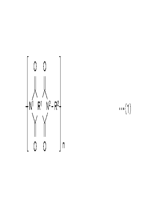
[0013]
[Chem. 1]
CA 03182821 2022- 12- 14
5
- -
0 0
A X
-N1 R1 N2_ R2¨ ...(1)
)i Y
0 0 n
- -
[0014]
Note that in the general formula (1), the Nl and the
N2 each represent nitrogen, the Rl comprises one or more
first aromatic rings, the Rl and the Nl form a first imide
ring the Rl and the N2 form a second imide ring, a first
steric structure of the one or more first aromatic rings, a
second steric structure of the first imide ring, and a third
steric structure of the second imide ring are not disposed
on a plane and make a bent configuration, the R2 comprises
one or more second aromatic rings comprising an aromatic
ring bonded to the N2, the aromatic ring comprises a first
carbon atom bonded to the N2, the aromatic ring comprises a
second carbon atom and a third carbon atom (ortho position
carbon atoms) respectively at positions neighboring to the
first carbon atom, at least one of the second carbon atom
and the third carbon atom has a substituent, a fourth steric
structure of the second imide ring (an imide structure) to
which the R2 is bonded and a fifth steric structure of the
aromatic ring to which the N2 is bonded are not disposed on
a same plane, and n represents an integer of one or greater.
Advantageous Effects of Invention
[0015]
The present invention makes it possible to provide a
radioactive noble gas removal filter, a filter unit, and a
nuclear reactor containment vessel vent system with improved
durability. Issues, configurations, and effects other than
those described above will be clarified by the following
description of embodiments.
CA 03182821 2022- 12- 14
6
BRIEF DESCRIPTION OF DRAWINGS
[0016]
FIG. 1 is a schematic configuration diagram showing
the configuration of a nuclear power plant including a
nuclear reactor containment vessel vent system according to
the present embodiment.
FIG. 2 is a partially cutaway perspective view showing
an aspect of the filter unit according to the present
embodiment.
FIG. 3 is a perspective view showing an aspect of the
filter according to present embodiment.
DESCRIPTION OF EMBODIMENTS
[0017]
Hereinafter, an embodiment of a radioactive noble gas
removal filter (hereinafter sometimes simply referred to as
"filter"), a filter unit, and a nuclear reactor containment
vessel vent system according to the present invention will
be described in detail with reference to the drawings as
appropriate. The filter according to the present embodiment
is particularly suitably used for selectively removing
radioactive noble gases in a filter unit and a nuclear
reactor containment vessel vent system.
These filter,
filter unit, and nuclear reactor containment vessel vent
system are all used in a nuclear power plant to depressurize
the nuclear reactor containment vessel by venting the gas in
the nuclear reactor containment vessel to the atmosphere in
the unlikely event of a severe accident. The filter and
filter unit are disposed on the vent line (vent pipe) of the
nuclear reactor containment vessel vent system. First, a
nuclear power plant and a nuclear reactor containment vessel
vent system where the filter is used will be described, and
then the filter unit and filter will be described.
[0018]
CA 03182821 2022- 12- 14
7
[Nuclear Power Plant and Nuclear Reactor Containment Vessel
Vent System]
Among the drawings referenced, FIG. 1 is a schematic
configuration diagram showing the configuration of a nuclear
power plant NPP including a nuclear reactor containment
vessel vent system VS according to the present embodiment.
Note that FIG. 1 shows an advanced boiling water reactor
(ABWR) including a nuclear reactor containment vessel vent
system VS.
[0019]
As shown in FIG. 1, the nuclear power plant NPP has a
nuclear reactor pressure vessel 3 containing a core 2 inside
a nuclear reactor containment vessel 1. The nuclear reactor
pressure vessel 3 includes a main steam pipe 4 connected
thereto to send steam generated in the nuclear reactor
pressure vessel 3 to a turbine (not shown).
[0020]
The interior of the nuclear reactor containment vessel
1 is partitioned into a dry well 5 and a wet well 7 by a
diaphragm floor 12 made of reinforced concrete. The wet
well 7 has a space inside which pool water is stored. A
pool in this wet well 7 is called a suppression pool 8. The
dry well 5 and wet well 7 are communicated with each other
via a vent pipe 11 having vent pipe exhaust portions ha.
Each vent pipe exhaust portion ha opens below the water
surface of the suppression pool 8 in the wet well 7.
[0021]
In the unlikely event of a pipe rupture accident where
some of the pipes are damaged to release steam into the
nuclear reactor containment vessel 1, the pressure in the
dry well 5 will rise due to the steam flowing out of the
rupture opening of the pipes. Note that this pipe rupture
accident is generally known by the name of LOCA, and could
CA 03182821 2022- 12- 14
8
occur in the dry well 5 through which the pipes pass. In
that case, due to the pressure difference between the dry
well 5 and the wet well 7, the steam released into the dry
well 5 is led through the vent pipe 11 and the vent pipe
exhaust portions ha to the pool water in the suppression
pool 8 in the wet well 7. The suppression pool 8 condenses
the steam with pool water to significantly reduce the volume
of the steam, thereby suppressing pressure rise in the
nuclear reactor containment vessel 1. Here, if radioactive
materials are contained in the steam, most of the radioactive
materials are removed by the scrubbing effects of the pool
water in the suppression pool 8.
[0022]
In addition, also when the pressure in the nuclear
reactor pressure vessel 3 or the main steam pipe 4 rises,
the steam is similarly released to the suppression pool 8,
which condenses it and thereby lowers the pressure in the
nuclear reactor pressure vessel 3 and the main steam pipe 4.
As a device for this purpose, for example, in an ABWR, a
steam release safety valve 6 for releasing steam is installed
in the space of the dry well 5 in the nuclear reactor
containment vessel 1, for example, at a given location in
the main steam pipe 4. The steam released through the steam
release safety valve 6 passes through a steam release safety
valve exhaust pipe 9 and is finally released from a quencher
10 into the suppression pool 8 and is condensed by the pool
water of the suppression pool 8. Then, as described above,
the suppression pool 8 condenses the steam into liquid water
to greatly reduce the volume of the steam, thereby
suppressing pressure rise in the nuclear reactor containment
vessel 1. Also here, if radioactive materials are contained
in the steam, most of the radioactive materials are removed
by the scrubbing effects of the pool water in the suppression
CA 03182821 2022- 12- 14
9
pool 8 in the same manner as described above.
[0023]
By condensing steam in the suppression pool 8 and
cooling the pool water in the suppression pool 8 with a
residual heat removal system (not shown), it is possible to
prevent temperature rise and pressure rise in the nuclear
reactor containment vessel 1 and settle the accident.
[0024]
However, in the unlikely event that the residual heat
removal system fails to function, the temperature of the
pool water in the suppression pool 8 will rise. As the
temperature of the pool water rises, the partial pressure of
the steam in the nuclear reactor containment vessel 1 rises
to the saturated vapor pressure for the temperature of the
pool water, so that the pressure in the nuclear reactor
containment vessel 1 rises. When such a pressure rise occurs,
the pressure rise can be suppressed by spraying cooling water
into the nuclear reactor containment vessel 1. In addition,
this spray can also be operated by connecting a fire pump or
the like from the outside.
[0025]
However, in the further unlikely event that this spray
also fails to work, the pressure in the nuclear reactor
containment vessel 1 will rise. When such a pressure rise
occurs in the nuclear reactor containment vessel 1, the gas
inside the nuclear reactor containment vessel 1 can be
released to the outside to suppress the pressure rise in the
nuclear reactor containment vessel 1.
This operation is
called a vent operation. In an ABWR, this vent operation is
performed by releasing the gas 7a in the wet well 7. This
makes it possible for the ABWR to release gas to the outside
after removing as much radioactive material as possible with
the pool water in the suppression pool 8.
CA 03182821 2022- 12- 14
10
[0026]
The ABWR has the above-described nuclear reactor
containment vessel vent system VS as a device for further
removing radioactive materials from the gas 7a to be released
to the outside in performing this vent operation.
The
nuclear reactor containment vessel vent system VS includes
a vent line 13 connected to the dry well 5 and the wet well
7 of the nuclear reactor containment vessel 1. The vent
line 13 includes isolation valves 14, a filter vent device
activation valve 27, and a rupture disk 28 bypassing the
filter vent device activation valve 27.
Normally, the
isolation valve 14a on the wet well 7 side is always open
(in FIG. 1, the isolation valve 14a in the open state is
shown in white), and the isolation valve 14b on the dry well
5 side is always closed (in FIG. 1, the isolation valve 14b
in the closed state is shown in black). The filter vent
device activation valve 27 is normally left closed (in FIG.
1, the filter vent device activation valve 27 in the closed
state is shown in black), but opens in the case of a
predetermined pressure or higher, and once opened, it remains
open until an instruction (signal) to close it again. By
keeping the isolation valve 14a on the wet well 7 side open
in this way, the pool water in the suppression pool 8 can
scrub the released gas and remove most of the radioactive
materials. This is a safety feature of ABWR.
[0027]
The rupture disk 28 is set to passively open at a
pressure equal to or higher than the pressure that activates
the filter vent device activation valve 27 and equal to or
lower than the resistance pressure of the nuclear reactor
containment vessel 1. The rupture disk 28 passively opens
under the above conditions when the filter vent device
activation valve 27 fails to open for some reason, so that
CA 03182821 2022- 12- 14
11
the nuclear reactor containment vessel 1 can be appropriately
decompressed.
Note that the rupture disk 28 may be an
explosion valve or other valve.
[0028]
In addition, the vent line 13 is connected to the inlet
pipe 17 of the filter container 16 in the filter vent device
constituted by the equipment within the dashed-dotted
lines. The tip side of the inlet pipe 17 is open inward the
filter container 16.
10 [0029]
Pool water 18 for scrubbing is stored in the lower
portion of the filter container 16. A metal filter 19 in
the form of a metal screen is installed on the upper side of
the filter container 16. To this metal filter 19, one end
15 of an outlet pipe 20 of the filter container 16 is connected.
The other end of the outlet pipe 20 passes through the
shielding wall 21 and is led out of the shielding wall 21.
The gas finally passes through a pipe 31 leading to the
exhaust stack 22 and is released from the exhaust stack 22
to the outside.
[0030]
The released gas entering the filter vent device 15 in
the vent line 13 includes aerosol-like radioactive materials
a, radioactive noble gases b, water vapor c, hydrogen d,
other gases e such as nitrogen, and the like. The released
gas that has entered the filter vent device 15 is further
scrubbed with pool water 18 for scrubbing, thereby mainly
removing most of the aerosol-like radioactive materials a.
Furthermore, the metal filter 19 and the iodine filter 38
remove gaseous radioactive materials such as iodine (not
shown).
[0031]
Most of the radioactive materials are removed by the
CA 03182821 2022- 12- 14
12
above operation, but the radioactive noble gas b has poor
reactivity, so that it cannot be removed only by the filter
vent device 15 having the configuration described so far.
Note that the released gas in the outlet pipe 20 released
from the filter vent device 15 having the configuration
described so far contains radioactive noble gases b, water
vapor c, hydrogen d, other gases e such as nitrogen, and the
like.
[0032]
[Filter Unit]
In view of the above, in the nuclear reactor
containment vessel vent system VS according to the present
embodiment, a filter unit 23 is installed on the outlet pipe
downstream of the filter vent device 15. The filter unit
15 23 includes a later-described filter (such as a hollow fiber
membrane 23a or a membrane filter 23h to be described later)
and a holding member configured to hold this filter (such as
a cylindrical body 23c and an end member 23d to be described
later), and can selectively remove radioactive noble gases.
20 That is, the filter unit 23 includes the later-described
filter, so that it is impermeable to radioactive noble gases
but permeable to water vapor and hydrogen. Therefore, the
filter unit 23 can release water vapor and hydrogen to the
outside to lower the pressure in the nuclear reactor
containment vessel 1.
[0033]
FIG. 2 is a partially cutaway perspective view showing
an aspect of the filter unit 23 according to the present
embodiment. As shown in FIG. 2, an example of the filter
unit 23 is a hollow fiber membrane module 23b where a later-
described filter is formed in a straw-shaped hollow fiber
membrane 23a and included therein. The hollow fiber membrane
module 23b includes a hollow fiber membrane 23a and, as
CA 03182821 2022- 12- 14
13
holding members configured to hold the same, a cylindrical
body 23c and bottomed cylindrical end members 23d at both
ends of the cylindrical body 23c. At the center of the
bottom portion 23e of each end member 23d, there is provided
a released gas inlet/outlet portion 23f for allowing the
released gas to enter and exit.
Multiple hollow fiber
membranes 23a are arranged in bundles in the hollow fiber
membrane module 23b.
The vicinity of the openings (not
shown) at both ends of the hollow fiber membrane 23a is fixed
with a fixing material such as resin so as not to block the
opening of each hollow fiber membrane 23a and to fill the
gaps between the multiple hollow fiber membranes 23a and the
gaps with the cylindrical body 23c. In addition, the opening
(not shown) at the end of the hollow fiber membrane 23a is
provided so as to face the release gas inlet/outlet portion
24f.
[0034]
The released gas enters from one opening of the hollow
fiber membrane 23a, flows through the inside of the hollow
fiber membrane 23a, and is discharged from the other opening.
Here, the water vapor c and hydrogen d contained in the
released gas permeate from the membrane surface of the hollow
fiber membrane 23a to the outside of the hollow fiber
membrane 23a. On the other hand, the radioactive noble gases
b and other gases e contained in the released gas are
discharged from the other opening of the hollow fiber
membrane 23a without permeating through the membrane surface
of the hollow fiber membrane 23a, and discharged through the
released gas inlet/outlet portion 23f of the end member 23d
to a return pipe 24. The released gas (radioactive noble
gases b and other gases e) discharged to the return pipe 24
is returned through a check valve 26 to the dry well 5. On
the other hand, the cylindrical body 23c includes a flow
CA 03182821 2022- 12- 14
14
port 23g at a given location thereof, and the water vapor c
and hydrogen d that have permeated through the membrane
surfaces of the hollow fiber membranes 23a are discharged
from the flow port 23g into the pipe 31, pass through the
pipe 31, and are discharged from the exhaust stack 22 to the
outside.
[0035]
Note that although the filter unit 23 can remove
radioactive noble gases at any position inside the nuclear
reactor containment vessel 1 or on the vent pipe, it is
preferably placed downstream of the filter vent device 15.
In this way, it is possible to prevent the aerosol-like
radioactive materials a from adhering to the filter unit 23
which would result in degrading the filter performance, and
from being exposed to the influence of molten fuel that may
occur in the event of an accident.
Therefore, the
reliability of the nuclear reactor containment vessel vent
system VS is improved.
[0036]
The hollow fiber membrane 23a used in the filter unit
23 is permeable to water vapor c and hydrogen d, but
impermeable to radioactive noble gases b.
That is, the
filter unit 23 can release the water vapor c and hydrogen d
that cause the pressurization of the nuclear reactor
containment vessel 1 while removing the radioactive noble
gases b.
However, as time passes, the filter unit 23
accumulates impermeable radioactive noble gases b, and as
the partial pressures of these gases increase, the permeation
amounts of water vapor c and hydrogen d decrease, so that
the function of lowering the pressure in the nuclear reactor
containment vessel 1 decreases. Therefore, the filter unit
23 and the nuclear reactor containment vessel 1 are connected
by the return pipe 24, and a blower 25 installed on the line
CA 03182821 2022- 12- 14
15
of the return pipe 24 returns the gases impermeable to the
hollow fiber membranes 23a to the nuclear reactor containment
vessel 1.
In this way, the nuclear reactor containment
vessel vent system VS can maintain the vapor permeation
performance of the filter unit 23. In addition, the nuclear
reactor containment vessel vent system VS includes the check
valve 26 on the line of the return pipe 24, so that it is
possible to prevent gas containing radioactive materials
from flowing back from the nuclear reactor containment vessel
1 to the filter unit 23 without passing through the filter
vent device 15.
[0037]
[Radioactive Noble Gas Removal Filter]
A filter used in the filter unit 23 includes a
polyimide film including a structural unit represented by
the general formula (1). Note that besides the hollow fiber
membrane 23a, this filter can be formed as a sheet-shaped
membrane filter 23h as shown in FIG. 3.
FIG. 3 is a
perspective view showing an aspect of the filter according
to the present embodiment.
[0038]
[Chem. 2]
_ _
0 0
A X
_N1 R1 N2-R2._ ...(1)
)i I(
_ 0 0 _ n
[0039]
Here, in the general formula (1), the Nl and the N2
each represent nitrogen. Therefore, as shown in the general
formula (1), the structural unit of the filter has an imide
structure containing the Nl (first imide ring) and an imide
structure containing the N2 (second imide ring). Hereinafter,
CA 03182821 2022- 12- 14
16
when there is no need to distinguish between the first imide
ring and the second imide ring, they are simply referred to
as imide rings.
[0040]
In addition, the R1 includes one or more aromatic rings,
the Rl and the Nl form a first imide ring the Rl and the N2
form a second imide ring, and a steric structure of the one
or more aromatic rings, a steric structure of the first imide
ring, and a steric structure of the second imide ring are
not disposed on a plane and make a bent configuration. For
example, a carbon that makes a single bond has four sp3
hybrid orbitals. These four sp3 hybrid orbitals are arranged
so as to face the vertices of a regular tetrahedron.
Therefore, the skeleton of a molecule centered on carbon
bonds to other atoms (such as hydrogen and carbon) at a bond
angle of 109.5 in the case of a single bond. Further, as
for nitrogen, single bond takes the form of a triangular
pyramid with the nitrogen at the vertex, and the bond angle
with other atoms is about 107 . Therefore, as described
above, the steric structure of the one or more first aromatic
rings, the steric structure of the first imide ring, and the
steric structure of the second imide ring are not disposed
on a plane and make a bent configuration.
[0041]
In addition, the R2 includes one or more aromatic rings
including an aromatic ring bonded to the N2, the aromatic
ring includes a first carbon atom bonded to the N2, the
aromatic ring includes a second carbon atom and a third
carbon atom (ortho position carbon atoms) respectively at
positions neighboring to the first carbon atom, at least one
of the second carbon atom and the third carbon atom has a
substituent.
[0042]
CA 03182821 2022- 12- 14
17
Further, a steric structure of the second imide ring
to which the R2 is bonded and a steric structure of the
aromatic ring to which the N2 is bonded are not disposed on
a same plane. As described above, as for nitrogen, single
bond takes the form of a triangular pyramid with the nitrogen
at the vertex, and the bond angle with other atoms is about
107 . Therefore, if N2 and R2 are bonded by a single bond,
a steric structure of the imide and a steric structure of
the aromatic ring are not disposed on a same plane.
Additionally, n represents an integer of one or more. Note
that the aromatic rings in the general formula (1) are
preferably benzene or naphthalene.
[0043]
The polyimide film including a structural unit
represented by the general formula (1) can be obtained, for
example, as a polymer by dehydration condensation of an acid
dianhydride represented by the general formula (2) and a
diamine represented by the general formula (3).
[0044]
[Chem. 3]
C) 0
A J1\
c) R3 C) ...(2)
I 1 I I
C) C)
[0045]
Note that in the general formula (2), the R3 includes
one or more aromatic rings. When the R3 includes multiple
aromatic rings, steric structures of those aromatic rings
are not disposed on a plane and make a bent configuration.
R3 in this the general formula (2) corresponds to Rl in the
general formula (1).
CA 03182821 2022- 12- 14
18
[0046]
[Chem. 4]
H2N-R4-NH2 ...(3)
[0047]
Note that in the general formula (3), the R4 includes
one or more aromatic rings, the one or more aromatic rings
includes fourth carbon atoms each bonded to an amino group,
there are a fifth carbon atom and a sixth carbon atom
respectively at positions neighboring to each of the fourth
carbon atoms, and at least one of the fifth carbon atom and
the sixth carbon atom has a substituent. R4 in this the
general formula (3) corresponds to R2 in the general formula
(1).
[0048]
Here, in the conventional polyimide film, the imide
rings constituting it are hydrolyzed by relatively high-
temperature water vapor to form polyamic acid, which is
further decomposed into carboxylic acid and amine. This
reduces the tensile elongation at break of the material and
makes it brittle. This hydrolysis reaction is thought to
occur when electrons of OH- contained in high-temperature
water molecules enter electron orbits possessed by the imide
rings. The hydrolysis reactivity here is determined by the
energy difference (gap) between the electron unoccupied
orbital energy level spreading around the imide rings and
the highest occupied molecular orbital (HOMO) energy of OH-.
In other words, the hydrolysis reactivity here can be
quantitatively evaluated by obtaining these energies. When
the energy difference is large, it means that it is easier
to stabilize by reaction, so that it can be judged that the
hydrolysis reaction proceeds easily.
[0049]
CA 03182821 2022- 12- 14
19
On the other hand, it is thought that as the energy
level of the unoccupied electron orbital spreading around
the imide rings increases in accordance with the combination
of the acid dianhydride and the diamine, the energy
difference between the unoccupied orbital energy levels of
electrons spreading around the imide rings and the HOMO
energy of OH- decreases. Therefore, it is considered that
the hydrolysis reactivity is lowered and a molecular
structure satisfying the desired performance is obtained.
[0050]
The unoccupied orbital energy level of the structure
located on the imide rings can be obtained, for example, by
simulation as follows.
[0051]
(1) For a combination of an acid dianhydride and a
diamine, a low molecular weight chain model is created that
is formed of three consecutive structural units represented
by the general formula (1).
[0052]
(2) For the created low molecular weight chain model,
a steric dimensional structure is created that realizes
general interatomic distances, bond angles, and dihedral
angles. Then, an appropriate dihedral angle is selected so
that there is no molecular overlap or intersection, and the
angle is changed to generate up to 100 structural isomers
different from the initial one.
[0053]
(3) Each structure obtained is used as an initial value
to compute the closest energy stabilization structure and
calculate the energy.
This calculation/computation is
obtained, for example, by using DFTB (Density Functional
based Tight-Binding) from SCM and performing structural
optimization calculation using DFTB. org/3ob-3-1 parameters.
CA 03182821 2022- 12- 14
20
[0054]
(4) The energy of each structure obtained is compared,
and the structure with the minimum energy is defined as the
most stable structure, and energy calculation is performed
by the density functional theory considering dispersion
terms to compute the energy level of the entire molecule.
This computation is obtained, for example, by using Gaussian
09 from Gaussian, using APFD as the functional and 6-31G(d,p)
as the basis function.
[0055]
(5) Among the obtained energy levels, the orbital when
the energy level of the unoccupied orbital has an isosurface
value of 0.01 in ascending order is calculated, and if the
orbital spreads directly above either of the two central
imide rings among the three repeating structures, the energy
value is recorded. If the lowest unoccupied orbital does
not correspond to an imide ring, the unoccupied orbital of
one higher energy level is similarly calculated.
This
operation is performed until an orbital extending around the
target imide ring is found.
[0056]
(6) The energy levels of the unoccupied orbitals thus
obtained are compared for combinations of acid dianhydrides
and diamines, and it is judged that the higher the energy
level, the lower the hydrolyzability.
[0057]
As for the height and reactivity of the energy levels
of the unoccupied electron orbitals spreading around the
imide rings, examples of the generally known BPDA-PPD
(3,3',4,4'-biphenyltetracarboxylic
dianhydride-p-
phenylenediamine) represented by the chemical formula (4)
and PMDA-ODA (pyromellitic dianhydride-oxydianiline)
represented by the chemical formula (5) will be given.
CA 03182821 2022- 12- 14
21
[0058]
[Chem. 5]
_
401041 0
ND N¨ ¨(4)
0 0
_
[0059]
[Chem. 6]
_
0
0 N 0...(5)
¨N 0
0
[0060]
The unoccupied orbital energy levels of electrons
spreading around the imide rings were -68.33521 kcal/mol for
BPDA-PPD represented by the chemical formula (4), and -
79.65298 kcal/mol for PMDA-ODA represented by the chemical
formula (5).
From this, it is considered that BPDA-PPD
represented by the chemical formula (4) is less likely to be
hydrolyzed than PMDA-ODA represented by the chemical formula
(5). In fact, the results of investigating deterioration
resistance under basic conditions have been reported (NASA
Technical Memorandum 102726). In the report, the tensile
strength of BPDA-PPD represented by the chemical formula (4)
only decreased to about 85% in a severe test of immersion in
a basic solvent of pH 11 to 14 at room temperature for 48
hours.
On the other hand, PMDA-ODA represented by the
chemical formula (5) showed that the tensile strength
decreased to 60% at pH 11 and decomposed at pH 14. The
results of this severe test show that the decomposability is
higher by basicity, that is, by OH- than by water, and it is
CA 03182821 2022- 12- 14
22
considered that the same trend will be observed in a severe
test under superheated water vapor conditions. Therefore,
in order to suppress hydrolysis by relatively high-
temperature water vapor and improve durability, it would be
preferable to provide a structure where electrons spreading
around the imide rings have high unoccupied orbital energy
levels.
[0061]
Based on the above considerations, the present
inventors diligently studied a structure where the
unoccupied orbital energy levels of electrons spreading
around the imide rings are high. As a result, the present
inventors have found that the energy levels increase when
the planar structure of the imide rings and the planar
structure of the aromatic rings bonded with the amino groups
on the diamine side are not disposed on a same plane and
make a twisted configuration.
[0062]
In addition, the present inventors have found in the
above studies that the structure of an acid dianhydride has
low planarity, and when it has a structure with wide electron
orbits and no conjugated structure, the unoccupied orbital
energy levels of electrons spreading around the imide rings
are high. From this point of view, in the general formula
(1), it can be said that it is preferable that the Rl
comprises two or more first aromatic rings, and a first
aromatic ring and a first aromatic ring are bonded together
by at least one selected from the group consisting of sp3
carbon, a sulfonyl group, a ketone bond, and an ether bond.
In this case, if the first aromatic ring and the first
aromatic ring in Rl are bonded with any of these, the
structure of the acid dianhydride more reliably has low
planarity, making it possible to obtain a structure with
CA 03182821 2022- 12- 14
23
wide electron orbits and no conjugated structure. Then, the
acid dianhydride for obtaining this is the compound
represented by the above the general formula (2), and
specific examples thereof include the compounds represented
by the chemical formulas (6) to (8).
[0063]
[Chem. 7]
o
0
1 0 o
...(6)
/7
0 0
1 0
0
[0064]
[Chem. 8]
o
F F
0
1 F 0
-(7)
0 F 0
F F
0
[0065]
[Chem. 9]
CA 03182821 2022- 12- 14
24
0
o
0
o
0
1
o
o
...(8)
o
[0066]
Furthermore, the present inventors have found in the
above studies that a diamine takes a twisted structure when
there is a substituent other than a hydrogen atom at C at
the position neighboring to C in the aromatic ring bonded
with an amino group (that is, ortho position). It can be
said that it is preferable that the substituent is at least
one selected from the group consisting of an alkyl group
having a molecular weight of a methyl group or higher, a
halogen-substituted alkyl group where at least one hydrogen
atom in an alkyl group is substituted with a halogen element,
and a halogen element.
Moreover, as a substituent, for
example, a sulfo group, a ketone group, a hydroxyl group, an
amine, or the like can be used. With these substituents,
the diamine can more reliably have a twisted structure.
Examples of halogen elements include fluorine, chlorine,
bromine, iodine, astatine, and tennessine. Further, from
the viewpoint of forming the diamine into a twisted structure,
in the general formula (1), it is preferable that the R2
includes a first aromatic ring bonded to the N2 and a second
aromatic ring bonded to the first aromatic ring via a bonding
group, the first aromatic ring includes a first carbon atom
bonded to the N2, and the bonding group is bonded to a second
carbon atom at a position neighboring to the first carbon
atom. Also, it is preferable that the bonding group is at
least one selected from the group consisting of C, S, and 0.
CA 03182821 2022- 12- 14
25
In this way, it is possible to more reliably form the diamine
into a twisted structure. The diamine for obtaining this is
the compound represented by the general formula (3), and
specific examples thereof include the compounds represented
by the chemical formulas (9) to (11).
[0067]
[Chem. 10]
NH2 NH2
1110 S 111111
¨(9)
[0068]
[Chem. 11]
CH3
I
1110 NH
o 1110
o
I
' ' ' ( 1 0 )
CH3
H2N
[0069]
[Chem. 12]
H3C =--(11)
CH3
H2N NH2
H3C
CH3
[0070]
Note that in the diamine represented by the general
formula (3), there are two carbon atoms bonded with amino
groups, and each of these carbon atoms has two ortho position
carbon atoms. In the present embodiment, only one of the
CA 03182821 2022- 12- 14
26
carbon atoms may be ortho-positioned to the carbon atom
bonded with an amino group.
Examples of such diamines
include the compound represented by the chemical formula
(12).
[0071]
[Chem. 13]
H2N ....õ..... ..17, NH2
1 1 ' ' '
(12)
./' .......,..
H3C CH3
[0072]
Even if the diamine represented by the general formula
(3) has a highly planar structure, when it has any of the
substituents described above, the unoccupied orbital energy
levels of electrons spreading around the imide rings increase,
contributing to stabilizing the structure of the entire
polyimide film including the structural unit represented by
the general formula (1) after polymerization. Examples of
diamines having a highly planar structure and including any
of the substituents described above include compounds
represented by the chemical formulas (13) and (14).
[0073]
[Chem. 14]
H3C CH3
H2N
. NH2 ... (13)
H3C CH3
[0074]
[Chem. 15]
CA 03182821 2022- 12- 14
27
H3C CH3
H2N
111" llik NH 2 = = = (1
4)
H3C CH3
[0075]
According to the film described above, it is considered
that the unoccupied orbital energy levels of electrons
spreading around the imide rings are high and the gap between
the unoccupied orbital energy levels of electrons spreading
around the imide rings and the HOMO energy of OH- is small.
For this reason, the film according to the present embodiment
has low hydrolysis reactivity and high durability even when
it comes into contact with relatively high-temperature water
vapor.
Therefore, a filter unit using this film and a
nuclear reactor containment vessel vent system using the
filter unit also have high durability. Then, even in the
unlikely event that gas containing radioactive materials
flows out of the nuclear reactor pressure vessel into the
nuclear reactor containment vessel to pressurize the nuclear
reactor containment vessel, the use of the film according to
the present embodiment makes it possible to remove all
radioactive materials, including radioactive noble gases,
when releasing the gas from the nuclear reactor containment
vessel.
Therefore, the film, filter unit, and nuclear
reactor containment vessel vent system according to the
present embodiment can prevent pressurization of the nuclear
reactor containment vessel and minimize radioactive
materials leaking to the outside.
Examples
[0076]
In order to quantitatively compare hydrolysis
CA 03182821 2022- 12- 14
28
resistance, a deterioration test was performed by immersing
13 types of polyimides described in the results of
investigating deterioration resistance under basic
conditions (NASA Technical Memorandum 102726) in a basic
aqueous solution at room temperature for 2 days. Note that
since Kapton and Apical are structurally the same, only
Kapton was employed. Then, an estimation formula was created
using the results of investigating changes in tensile
strength.
[0077]
The basic aqueous solution test at pH = 11 was used as
the test condition, and the value to be compared was the
retention rate (%) of the tensile strength before and after
deterioration. For polyimide, random forest regression
prediction by scikit-learn was performed using the retention
rate of tensile strength as the objective variable and nine
explanatory variables calculated from the molecular
structure. The nine explanatory variables are as follows.
1. Energy level of the unoccupied orbital described
above
2 to 4. Hansen solubility parameters (5P, 5D, 5H) (for
a structure with one repeating structure, excluding diamines
and acid anhydrides appearing at the ends)
5. Cosine of the angle between the planes of imide ring
and benzene ring attached to it
6. Number of aromatic rings (assuming three repeating
structures)
7. Percentage of number of aromatic bonds among all
interatomic bonds excluding hydrogen (assuming three
repeating structures)
8. Number of rotatable bonds (assuming three repeating
structures)
9. Ratio of sp3 carbons to the total number of carbons
CA 03182821 2022 12 14
29
(assuming three repeating structures)
[0078]
Since there are 13 experimental datasets, seven of them
were used as learning data and the remaining six were used
as verification data. Prediction was performed with 1000
trees used for learning. A prediction model was used with
a coefficient of determination of R2 = 0.90 for learning
data and a coefficient of determination of R2 = 0.73 for
verification data. As a result, it was predicted that a
structure would be obtained with the tensile strength showing
an average retention rate of 84% and a maximum retention
rate of 92% for polyimides made from combinations of acid
dianhydrides and diamines having the above characteristics,
for example, combinations of acid dianhydrides of chemical
formulas (6) to (8) and diamines of chemical formulas (9) to
(14).
[0079]
The radioactive noble gas removal filter, the filter
unit, and the nuclear reactor containment vessel vent system
according to the present invention have been described above
in detail through embodiments and examples, but the gist of
the present invention is not limited to this, and includes
various modifications.
For example, the above-described
embodiments have been described in detail in order to explain
the present invention in an easy-to-understand manner, and
are not necessarily limited to those having all the described
configurations. Also, some of the configurations of one
embodiment can be replaced with the configuration of another
embodiment, and the configuration of one embodiment can be
added to the configuration of another embodiment. Moreover,
it is possible to add, delete, or replace some of the
configuration of each embodiment with those of another
configuration.
CA 03182821 2022- 12- 14
30
Reference Signs List
[0080]
1 nuclear reactor containment vessel
13 vent line
23 filter unit
NPP nuclear power plant
VS nuclear reactor containment vessel vent system
a aerosol-like radioactive materials
b radioactive noble gases
c water vapor
d hydrogen
e other gases such as nitrogen
CA 03182821 2022- 12- 14