Note : Les descriptions sont présentées dans la langue officielle dans laquelle elles ont été soumises.
CA 03183900 2022-11-17
WO 2021/245335 PCT/F12021/050401
1
Controlling boom of work machine
Background of the invention
The invention relates to controlling a boom assembly of a work ma-
chine, and in particular to controlling a boom of a work machine by making use
of
so-called tip control.
A challenge in controlling a boom assembly of a work machine is to be
able to control the boom assembly fast and reliably in all usage situations as
de-
sired.
Brief description of the invention
It is an object of the invention to develop a new method, control system,
work machine, and computer program product. The solution according to the in-
vention is characterized by what is disclosed in the independent claims.
Preferred
embodiments of the invention are disclosed in the dependent claims.
In the disclosed solution, the boom assembly of a work machine is con-
trolled by tip control. In tip control, a control command is given to a tip of
a boom
assembly, converted into control commands for individual actuators of the boom
assembly. In the disclosed solution, a variable related to a load and its
position at
the tip of the boom assembly is defined, and the variable in question related
to the
load and its position at the tip of the boom assembly is taken into account in
the
control command to an actuator. With such a solution, it is possible to
control an
actuator to move very precisely at a desired speed along a desired path in
various
situations. It is even possible to maintain the precise speed and desired path
even
if a force that the actuator is subject to were to change during the movement.
Dif-
ferent situations may be the result of a weight change of a load being
controlled by
the tip of the boom assembly, or of a change in the location of the tip of the
boom
assembly. The movement of an actuator at a desired speed and along a desired
path
is important for the tip of a boom assembly to move as desired at all times.
According to an embodiment, converting a control command of a tip of
a boom assembly into control commands for individual actuators comprises form-
ing a speed request for an individual actuator, with the control command being
the
magnitude of the control signal for the actuator. The magnitude of the
actuator's
control signal in such a case depends on the speed request of the actuator and
the
variable in question related to the load and its location at the tip of the
boom as-
sembly. This way, implementing control is simple and straightforward.
CA 03183900 2022-11-17
WO 2021/245335 PCT/F12021/050401
2
According to an embodiment, a table is compiled on the interrelations
between the magnitude of a control signal of an actuator, speed request of the
ac-
tuator, and the variable related to the load and its position at the tip of
the boom
assembly, and the magnitude of the actuator's control signal is determined
from
the table in question. Forming, using, and administering the table is
straightfor-
ward and efficient.
According to an embodiment, a largest allowed limit value is deter-
mined for the difference between the speed of the actuator and speed request
of
the actuator, the speed of the actuator is measured, the speed of the actuator
is
compared to the speed request of the actuator, and if the difference between
the
measured speed and speed request exceeds the allowed limit value, the table in
question is calibrated. This allows control to be maintained precise and
managed
even if changes took place in the conditions and/or equipment, which tend to
de-
crease the reliability of control.
According to an embodiment, the variable in question related to the
load and its position at the tip of the boom assembly is the pressure on the
boom
assembly actuator. Measuring pressure is relatively simple, and the
correlation be-
tween the actuator pressure and control precision is surprisingly good.
Brief description of the drawings
The invention will now be described in more detail in connection with
preferred embodiments and with reference to the accompanying drawings, in
which:
Figure 1 shows work machine;
Figure 2 shows a second work machine;
Figure 3 is a diagram related to hydraulic and electrical control related
to tip control;
Figure 4 shows a flow chart of a method according to an embodiment;
Figure 5 shows a flow chart of calibration according to an embodiment;
Figure 6 shows an example of a table illustrating interrelations between
variables being used; and
Figure 7 shows an example of the table in Figure 6 when calibrated.
Detailed description of the invention
In tip control, an operator gives a command to a tip of a boom assembly
with a control device, in other words, a request to move to a particular
direction at
a particular speed. A required speed of movement is calculated for each
actuator of
CA 03183900 2022-11-17
WO 2021/245335 PCT/F12021/050401
3
the boom assembly so that by the joint effect of the different actuators of
the boom
assembly, the desired movement of the tip of the boom assembly is achieved.
So, in top control, an operator's control command for moving the boom
tip is implemented by dividing the control command into movement of individual
booms to move the boom tip according to the control command, by using boom
positions and state of motions measured with sensors. The desired movement of
the boom tip is divided into parts for different booms by making use of the so-
called
Jacobian matrix, for example. For implementing tip control, guidance can be
found
in the following literature references, for example: Bjorn Lofgren: Kinematic
Con-
trol of Redundant Knuckle Booms, Licentiate thesis, Department of Machine De-
sign, Royal Institute of Technology, Stockholm, 2004; BjOrn LOfgren: Kinematic
Control of Redundant Knuckle Booms with Automatic Path-Following Functions,
Doctoral thesis, Department of Machine Design, Royal Institute of Technology,
Stockholm, 2009; Mikkel M. Pedersen, Michael R. Hansen, Morten Ballebye: Devel-
oping a Tool Point Control Scheme for a Hydraulic Crane Using Interactive Real-
time Dynamic Simulation: Modelling, Identification and Control, Vol. 31, No.
4,
2010, pp. 133-143, ISSN 1890-1328.
With reference to Figures 1 and 2, Figures 1 and 2 show working ma-
chines. A working machine 1 may comprise a mobile working machine 1 and par-
ticularly advantageously a mobile working machine 1 adaptable to move in an in-
clined and/or uneven surface. Such a mobile working machine may be, for
example,
a forest work unit, such as a forwarder as in Figure 1, a harvester as in
Figure 2, or
another forest machine, such as a drive machine of another type suitable for
carry-
ing a load, or a combination of a forwarder or harvester, or another mobile
working
machine such as a mining machine or excavator.
The work machine 1 may comprise one or more frame parts 11. A boom
assembly 14 may be adapted on at least one frame part 11. The working machine
may also comprise a tool 16 adapted to the boom assembly 14, for example. The
tool may comprise, for example, a hoisting member, such as a load bucket
and/or a
wood handling tool, such as a harvester head. The forest machine may be body-
steered and comprise at least two body parts 11.
Depending on the embodiment, the working machine 1 may also com-
prise other structural parts. For example, the working machine 1 may comprise
a
control cabin 12 adapted on at least one body part 11. The work machine 1 may
further comprise moving means 13, which moving means 13 may comprise at least
one of the following: wheels adapted on an axle, wheels adapted on a swinging
axle,
CA 03183900 2022-11-17
WO 2021/245335 PCT/F12021/050401
4
wheels adapted on a tandem axle, a track system or another means known per se
to cause the work machine to move in relation to its working surface.
The boom assembly 14 may be adapted to the frame or control cabin
12. The cabin 12 and/or boom assembly 14 may be adapted foldably and/or rotat-
ably in relation to the carriage. It will be obvious for a person skilled in
the art that
the working machine 1 typically comprises numerous additional structural and
functional structure parts and entities depending on the type of the working
ma-
chine, such as a cargo space 15, power source 17, and so forth.
In Figure 1, the boom assembly 14 is formed so that a base with a slew-
ing ring is fixed to the work machine 1. The slewing ring further has a lower
ring
and an upper ring bearing-mounted in relation to each other. The upper ring is
ro-
tated by a toothed-bar machine unit operated by hydraulic cylinders.
A crane column is attached to the upper ring. The crane column in turn
has a lifting boom 18 pivoted to it. The lifting boom 18 is moved by a lifting
cylinder
.. 19.
Further, a luffing boom 20 is pivoted to the lifting boom 18. The luffing
boom 20 is moved by a folding cylinder 21. The luffing boom 20 may have a tele-
scopic extension moved by its own actuator. At the end of the telescopic
extension,
a tool such as a load bucket may reside.
As concerns the basic solution, the boom assembly 14 of Figure 2 cor-
responds to the boom assembly 14 of Figure 1. However, with regard to the
base,
the boom assembly 14 of Figure 2 differs from the structure of Figure 1. In
the so-
lution of Figure 2, the upper ring of the swivel ring is provided with an
inner tooth-
ing and it is rotated by a motor which rotates a gearwheel against the inner
tooth-
ing.
The boom assembly 14 may also be described as having, as its succes-
sive parts, a ring base to be rigidly connected to a work machine, a foot
section
rotatably bearing-mounted to the ring base, a first boom pivoted to the foot
section,
a second boom pivoted to the first boom, and possibly a telescopic arrangement
in
the second boom. In addition, the boom assembly comprises actuators to operate
each successive part.
In connection with each part of the boom assembly 14, a travel speed
sensor is adapted. For reasons of clarity, Figures 1 and 2 schematically
illustrate
only the travel speed sensor 22 of the lifting boom and the travel speed
sensor 23
of the luffing boom, but advantageously, as mentioned in the above, there is a
travel
speed sensor in connection with each part of the boom assembly 14.
CA 03183900 2022-11-17
WO 2021/245335 PCT/F12021/050401
The travel speed sensor may be a position sensor, for example. A travel
speed sensor allows, for example, an angle and angular acceleration of a boom
to
be measured. Further, a travel speed sensor allows, for example, the position
of the
boom and travel speed of a piston of the actuator cylinder to be measured. For
ex-
5 ample,
with the travel speed sensor 22 of the lifting boom the speed of the lifting
cylinder 19, and with the travel speed sensor 23 of the luffing boom the speed
of
the folding cylinder 21 may be measured. The travel speed sensor may comprise
an inclinometer and/or gyroscope, for example. Further in the embodiment of
Fig-
ure 1, for example, there may be a magnetostrictive linear sensor in
connection
with the base as the travel speed sensor, providing information on the turning
an-
gle. Likewise, the telescopic extension may have a magnetostrictive linear
sensor
as the travel speed sensor. In the embodiment of Figure 2, the motor rotating
the
gearwheel that is in connection with the base may be associated with a
rotation
angle sensor providing information on the turning angle.
Furthermore, the boom assembly 14 has pressure sensors in connec-
tion with each actuator, measuring the pressure at the actuator. For reasons
of clar-
ity, Figures 1 and 2 illustrate schematically only the pressure sensor 24 in
connec-
tion with the lifting cylinder, and the pressure sensor 25 in connection with
the
folding cylinder, but advantageously, as mentioned in the above, there is a
pressure
sensor in connection with each actuator of the boom assembly 14. A pressure
sen-
sor may in principle be adapted in any place of a pressure system. However, a
pres-
sure sensor is advantageously connected in connection with an actuator, to the
pressure hose bringing in pressure to it. The measured pressure is the
pressure of
the pressure medium of the pressure system. The pressure medium is a fluid
suit-
able for the purpose. For example, the fluid in connection with a hydraulic
actuator
may be hydraulic fluid and in connection with a pneumatic actuator the fluid
may
be pressurized air, for example.
In a previous solution, when a tip of the boom assembly 14 is close to
the work machine 1 and the load on the boom assembly 14 is light, the tip of
the
boom assembly 14 follows the control commands rather precisely. However, when
the tip of the boom assembly 14, for example, has been far away from the work
machine land has had a heavy load on it, the speed of the tip of the boom
assembly
14 has not matched what was requested. It has now been detected that in the
latter
case the pressure on the lifting cylinder, for example, is larger than in the
first case.
In the current solution set forth, the magnitude of the control signal of the
lifting
cylinder is changed on the basis of a pressure measurement, that is, to
establish the
CA 03183900 2022-11-17
WO 2021/245335 PCT/F12021/050401
6
same speed request as a higher pressure is detected, the magnitude of the
control
signal is increased.
Thus, the pressure on the actuator depends on the load and its location
at the tip of the boom assembly 14. This means that instead of a pressure
measure-
ment, the solution described herein allows the use of another variable related
to
the load and its location at the tip of a boom assembly, than the pressure on
the
actuator Such a variable may be determined, for example, by measuring the mass
of a load at the tip of the boom assembly 14 with a weighing sensor and by
deter-
mining its position in relation to a fulcrum. This way, a torque in relation
to a de-
sired fulcrum can be determined.
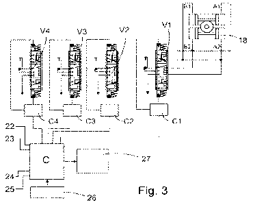
Figure 3 shows a diagram of a tip control related system. The system
includes a control unit C. Advantageously the control unit C is part of the
control
system of the work machine 1, but it is herein described as a separate part
for rea-
sons of clarity.
Control commands are fed to the control unit C with a controller 26. The
controller 26 may comprise stick controllers, keyboards, pointers of a
graphical
user interface and/or their combinations or other similar controller members.
In
connection with the controller C, there is additionally a display 27 to
illustrate the
operation of the work machine 1.
Furthermore, information from the travel speed sensors 22, 23 and
pressure sensor 24, 25 is fed to the control unit C. The actuators are
operated with
proportional valves V1, V2, V3, and V4. For reasons of clarity, Figure 3 only
shows
a lifting cylinder 18 of the actuators. Electric control takes place by means
of auxil-
iary control members Cl, C2, C3, and C4 from the control unit C.
The control unit C converts the control command of the boom tip, com-
ing from the controller 26, into a control command for each actuator. The
control
unit C notes the information from the sensors and provides a control signal
value
to the auxiliary control members. The control signal may comprise, for
example,
control current or control voltage. In such a case, then, the control signal
value is,
for example, a control current value (typically of milliamperes) or a control
voltage
value (typically of volts). The control signal may further comprise another
variable
having an effect on the opening of a valve.
The flow chart of Figure 4 illustrates a method according to an embodi-
ment. In block 28, a control command is issued to a tip of a boom. In block
29, the
control command of the tip of the boom is converted into a control command for
CA 03183900 2022-11-17
WO 2021/245335 PCT/F12021/050401
7
each actuator. So, a cylinder speed command, that is, a cylinder speed
request, is
given to the cylinder of each actuator.
Block 30 describes the forming and storing of a table which shows the
interrelations between the cylinder speed request, pressure at the actuator,
and
the control signal value of the control signal fed to the actuator, that is,
to the pre-
control valve (the proportional valves Vito V4 in Figure 3). An example of
such a
table is illustrated with Figure 6. In the example of Figure 6, the control
signal is
control current.
Figure 6 has the cylinder speed request v (m/s) on the x-axis, pressure
p (bar) on the y-axis, and control current value I (mA) on the z-axis. As
shown in
Figure 6, it is typical that the control current value I is naturally the
larger the
higher the speed request v is. However, it is particularly noteworthy that if
the
speed request v does not change, but the pressure p, for example, increases,
the
control current value I also increases.
In block 31, the pressure on the actuator is measured. In block 32, a con-
trol signal value is retrieved from the table formed in block 30,
corresponding to
the cylinder speed request formed in block 29 and the pressure measured in
block
31. In block 33, this control signal is fed to the pre-control valve.
Calibration according to an embodiment is illustrated by a flow chart
according to Figure 5. In block 34, calibration is switched on. An operator
may
switch on calibration when desired, for example. For example, it is possible
to give
an indication to the operator from the comparison of block 36, if the detected
dif-
ference is too large, and the operator may react to such an indication when
getting
one. Calibration may also be started automatically in response to too large a
differ-
ence having been detected in block 36. Calibration may be implemented as a
sepa-
rate work stage, or calibration may be implemented in the background during
nor-
mal working.
In block 35, the realized cylinder speed is measured. In block 36, the
realized cylinder speed is compared to the cylinder speed request, and the
differ-
ence between the measured realized speed and speed request exceeds the allowed
limit value, the table in question is calibrated at the operating point in
question, so
the option YES, and table updating in block 37. If the difference does not
exceed the
limit value, the option NO is followed, and the table is not in this regard
updated -
block 38.
Block 37 may have feedback to block 34 to continue calibration. Calibra-
tion may also be continued at other operating points, for example. Calibration
may
CA 03183900 2022-11-17
WO 2021/245335 PCT/F12021/050401
8
also be utilized in the forming of the table in question. The table may be two-
di-
mensional to begin with, that is, it has the relation between the speed
request and
control signal value on at one pressure level, only. With the calibration
procedure,
the values in question can then be formed at other pressure levels.
The computer program product in the control unit C comprises com-
puter-readable program code which is arranged to implement the functions of
the
disclosed tip control or the steps of the method that carries out the
functions as the
program code is being performed by a processor. The control unit C comprises
pro-
cessing means or a processor. The control unit C may comprise memory in which
information has been gathered and stored as well as is being gathered and
stored.
The processing means may be adapted to carry out at least part of the process
steps
and/or operations disclosed in this specification. In an embodiment, the
processing
means may be adapted to receive and send information and commands. The pro-
cessing means may comprise a programmable logic and/or programmable micro-
processor, for example. The processing means may form the control unit C or a
part
thereof.
An embodiment comprises a computer program comprising a program
code which, when executed on a computer, executes functions according to any
of
the embodiments described above. The computer program may be included in a
computer-readable storage medium, for instance in a non-volatile memory.
An embodiment comprises a computer program product comprising a
computer program according to an embodiment for executing functions according
to any of the embodiments described above.
In an embodiment, the apparatus comprises processing means config-
ured to execute functions described in an embodiment. The processing means may
serve as a computer for executing the program code. The processing means may
comprise at least one processor, memory and program platform capable of execut-
ing the program code.
Embodiments can be implemented as a computer process that is de-
fined by a computer program. The computer program may be in source code for-
mat, object code format or an intermediate format, and the computer program
can
be stored on a storage medium that may be any piece or apparatus that is
capable
of storing the computer program. For instance, a computer program can be
stored
on a computer program distribution medium that can be read by a computer or
processor. The computer program distribution medium may comprise a storage
CA 03183900 2022-11-17
WO 2021/245335 PCT/F12021/050401
9
medium, computer memory, read-only memory (ROM), electric carrier wave, tele-
communications signal, and software distribution package, for instance.
In an embodiment, a computer program product may be stored on a
computer-readable media and executable by a processor, and the computer pro-
gram product may comprise computer-readable program code. This type of com-
puter program product may be arranged to execute at least some of the steps in
the
method described above, when the program code is run in a processor.
In the examples of the figures, the actuators are hydraulically operated,
in particular all the actuators (cylinders) of the boom assembly. If so
desired, the
actuators may be, for example, pneumatic or electrically operated actuators.
Those skilled in the art will find it obvious that, as technology advances,
the basic idea of the invention may be implemented in many different ways. The
invention and its embodiments are thus not restricted to the examples
described
above but may vary within the scope of the claims.