Note : Les descriptions sont présentées dans la langue officielle dans laquelle elles ont été soumises.
WO 2022/005714
PCT/US2021/036526
COILED VASCULAR ACCESS INSTRUMENT AND RELATED SYSTEMS
BACKGROUND
[0001] A catheter is commonly used to infuse fluids into vasculature
of a patient. For example,
the catheter may be used for infusing normal saline solution, various
medicaments, or total
parenteral nutrition. The catheter may also be used for withdrawing blood from
the patient.
[0002] The catheter may include an over-the-needle peripheral
intravenous ("IV-) catheter. In
this case, the catheter may be mounted over an introducer needle having a
sharp distal end. The
catheter and the introducer needle may be assembled so that the distal end of
the introducer needle
extends beyond the distal end of the catheter with the bevel of the needle
facing up away from skin
of the patient. The catheter and the introducer needle are generally inserted
at a shallow angle
through the skin into vasculature of the patient
[0003] In order to verify proper placement of the introducer needle
and/or the catheter in the
blood vessel, a clinician generally confirms that there is "flashback" of
blood in a flashback
chamber of the catheter assembly. Once placement of the needle has been
confirmed, the clinician
may temporarily occlude flow in the vasculature and remove the needle, leaving
the catheter in
place for future blood withdrawal or fluid infusion.
[0004] Blood withdrawal using the catheter may be difficult for
several reasons, particularly
when a dwell time of the catheter within the vasculature is more than one day.
When the catheter
is left inserted in the patient for a prolonged period of time, the catheter
or vein may be more
susceptible to narrowing, collapse, kinking, blockage by debris (e.g., fibrin
or platelet clots), and
adhering of a tip of the catheter to the vasculature. Due to this, the
catheter is often used for
acquiring a blood sample at a time of catheter placement, but the catheter is
less frequently used
-1 -
CA 03183974 2022- 12- 22
WO 2022/005714
PCT/US2021/036526
for acquiring a blood sample during the catheter dwell period. Therefore, when
a blood sample is
required, an additional needle stick is often used to provide vein access for
blood collection, which
may be painful for the patient and result in higher material costs.
[0005] In some instances, in order to avoid the additional needle
stick, a vascular access
instrument may be used to access the vasculature of the patient via the
catheter. The vascular access
instrument may be inserted through the catheter and into the vasculature to
extend a life of the
catheter and allow blood withdrawal through the catheter without the
additional needle stick.
[0006] The subject matter claimed herein is not limited to
embodiments that solve any
disadvantages or that operate only in environments such as those described
above. Rather, this
background is only provided to illustrate one example technology area where
some
implementations described herein may be practiced.
SUMMARY
[0007] The present disclosure relates generally to vascular access
devices. More particularly,
the present disclosure relates to a vascular access instrument, which may be
delivered through a
catheter assembly to vasculature of a patient via an instrument advancement
device. In some
embodiments, the vascular access instrument may facilitate an increased dwell
period of a catheter
of the catheter assembly within the vasculature of the patient. In some
embodiments, the
instrument advancement device may be used to advance the vascular access
instrument into the
catheter and/or beyond a distal end of the catheter when the catheter is
compromised to overcome
obstructions such as thrombus, valves, and/or a fibrin sheath in or around the
catheter that may
otherwise prevent blood draw. In some embodiments, the instrument advancement
device may
provide needle-free delivery of the vascular access instrument to the
vasculature of the patient for
-2-
CA 03183974 2022- 12- 22
WO 2022/005714
PCT/US2021/036526
blood collection, fluid delivery, patient or device monitoring, or other
clinical needs by utilizing
an existing catheter dwelling within the vasculature.
[0008] In some embodiments, the vascular access instrument may be
configured to insert
through a vascular access device, such as, for example, the catheter assembly.
In some
embodiments, the vascular access instrument may include a wire, which may be
monolithically
formed as a single unit. In some embodiments, the wire may include a coil
portion, which may
include multiple loops wound around a central axis. In some embodiments, the
wire may include
a core portion extending through the coil portion and aligned with the central
axis. In some
embodiments, the wire may include a bent portion connecting a distal end of
the coil portion with
a distal end of the core portion.
[0009] In some embodiments, the bent portion may form a distal end of
the wire. In some
embodiments, the bent portion may be disposed distal to the coil portion. In
some embodiments,
the distal end of the wire may be blunt. In some embodiments, the bent portion
may include a U-
shape. In some embodiments, the bent portion may include a loop.
[0010] In some embodiments, the coil portion may be formed by a flat
portion of the wire
wound around the central axis into the loops. As referred to in the present
disclosure, the term "flat
portion of the wire" may correspond to a portion of the wire that includes a
first side and a second
side opposite the first side, and the first side and/or the second side is
planar prior to the wire being
wound around the central axis into loops during manufacture. In some
embodiments, the first side
may form an outer surface of the coil. In some embodiments, the second side
may form an inner
surface of the coil portion. In some embodiments, the core portion may contact
the inner surface
of the coil portion.
-3-
CA 03183974 2022- 12- 22
WO 2022/005714
PCT/US2021/036526
[00111 In some embodiments, each of the loops of the coil portion may
be spaced apart from a
next adjacent loop of the loops. In some embodiments, each of the loops of the
coil portion may
contact the next adjacent loop of the loops around a circumference of the next
adjacent loop. In
some embodiments, the coil portion and/or the core portion may be cylindrical.
In some
embodiments, the core portion may be flat. In some embodiments, the core
portion may be offset
from the central axis. In some embodiments, a proximal end of the coil portion
may be joined to
the core portion. In some embodiments, the coil portion may be tapered. In
some embodiments, a
proximal end of the core portion may taper outwardly in a proximal direction.
[0012] In some embodiments, the wire may include a straight portion
connected to a proximal
end of the coil portion. In some embodiments, the straight portion may be
parallel to a proximal
end of the core portion. In some embodiments, an inner portion of the straight
portion and an inner
portion of the proximal end of the core portion may be joined together. In
some embodiments, the
inner portion of the straight portion and the inner portion of the proximal
end of the core portion
may not be joined together.
[0013] In some embodiments, the vascular access instrument may
include another wire coupled
to the straight portion and the proximal end of the core portion. In some
embodiments, the other
wire may include nitinol or stainless-steel. In some embodiments, a distal end
of the other wire
may be disposed proximal to the coil portion.
[0014] In some embodiments, the vascular access instrument may
include a tube surrounding
the straight portion and/or the proximal end of the core portion. In some
embodiments, the tube
may include nitinol or stainless-steel. In some embodiments, a distal end of
the tube may be
disposed proximal to the coil portion. In some embodiments, the tube may be
joined to the straight
portion and/or the proximal end of the core portion.
-4-
CA 03183974 2022- 12- 22
WO 2022/005714
PCT/US2021/036526
[00151 In some embodiments, a vascular access system may include the
catheter assembly,
which may include a catheter adapter and a catheter extending distally from
the catheter adapter.
In some embodiments, an instrument advancement device may be coupled to the
catheter
assembly. In some embodiments, the instrument advancement device may include
the vascular
access instrument. In some embodiments, the instrument advancement device may
be configured
to advance the vascular access instrument from a retracted position to an
advanced position beyond
a distal end of the catheter. In some embodiments, the distal end of the
catheter may include a
distal opening. In some embodiments, the coil portion may extend through the
distal opening of
the catheter in response to the vascular access instrument being in the
advanced position.
[0016] It is to be understood that both the foregoing general
description and the following
detailed description are examples and explanatory and are not restrictive of
the present disclosure,
as claimed. It should be understood that the various embodiments are not
limited to the
arrangements and vascular access instrumentality shown in the drawings. Also,
the drawings are
not necessarily to scale. It should also be understood that the embodiments
may be combined. For
example, one or more features of a particular vascular access instrument may
be combined with
one or more features of another particular vascular access instrument. It
should also be understood
that other embodiments may be utilized and that structural changes, unless so
claimed, may be
made without departing from the scope of the various embodiments of the
present disclosure. The
following detailed description is, therefore, not to be taken in a limiting
sense.
BRIEF DESCRIPTION OF THE SEVERAL VIEWS OF THE DRAWINGS
[0017] Example embodiments will be described and explained with
additional specificity and
detail through the use of the accompanying drawings in which:
-5-
CA 03183974 2022- 12- 22
WO 2022/005714
PCT/US2021/036526
[0018] Figure lA is an upper perspective view of an example vascular
access system,
illustrating an example vascular access instrument in an example retracted
position, according to
some embodiments;
[0019] Figure 1B is an upper perspective view of the vascular access
system, illustrating the
vascular access instrument in an example advanced position, according to some
embodiments;
[0020] Figure 1C is an enlarged upper perspective view of a portion
of the vascular access
system, illustrating the vascular access instrument in the advanced position,
according to some
embodiments;
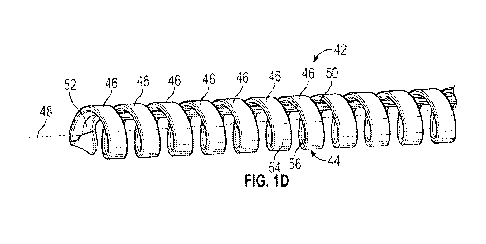
[0021] Figure 1D is an upper perspective view of an example distal
portion of the vascular
instrument, according to some embodiments;
[0022] Figure 2A is an upper perspective view of another vascular
access system, illustrating
the vascular access instrument in an example advanced position, according to
some embodiments;
[0023] Figure 2B is an upper perspective view of the distal portion
of the vascular access
instrument, illustrating an example U-shape, according to some embodiments;
[0024] Figure 2C is an upper perspective view of the distal portion
of the vascular access
instrument, illustrating a bent portion that includes the U-shape and an
example loop, according to
some embodiments;
[0025] Figure 3A is an upper perspective view of the distal portion
of the vascular access
instrument, illustrating an example distal end, according to some embodiments;
[0026] Figure 3B is a side view of the distal portion of the vascular
access instrument,
illustrating the distal end of Figure 3A, according to some embodiments;
[0027] Figure 3C is another upper perspective view of the distal
portion of the vascular access
instrument, illustrating an example closed coil portion, according to some
embodiments;
-6-
CA 03183974 2022- 12- 22
WO 2022/005714
PCT/US2021/036526
[0028] Figure 3D is an upper perspective view of an example proximal
portion of the vascular
access instrument, illustrating an example straight portion, according to some
embodiments;
[0029] Figure 3E is an upper perspective view of the proximal portion
of the vascular access
instrument, illustrating the straight portion and an example core portion
joined together, according
to some embodiments;
[0030] Figure 3F is an upper perspective view of the proximal portion
of the vascular access
instrument, illustrating the coil portion terminating at the core portion,
according to some
embodiments;
[0031] Figure 3G is an upper perspective view of the proximal portion
of the vascular access
instrument, illustrating an example twist, according to some embodiments;
[0032] Figure 3H is an upper perspective view of the proximal portion
of the vascular access
instrument, illustrating the straight portion and an example bend, according
to some embodiments;
[0033] Figure 31 is an upper perspective view of the coil portion,
illustrating an example taper,
according to some embodiments;
[0034] Figure 3J is a side view of the coil portion, illustrating the
taper, according to some
embodiments;
[0035] Figure 4A is an upper perspective view of the distal portion
of the vascular access
instrument, illustrating an absence of the core portion, according to some
embodiments;
[0036] Figure 4B is an upper perspective view of the proximal portion
of the vascular
instrument, illustrating the absence of the core portion, according to some
embodiments;
[0037] Figure 5 is an upper perspective view of an example tapered
core portion, according to
some embodiments;
-7-
CA 03183974 2022- 12- 22
WO 2022/005714
PCT/US2021/036526
[00381 Figure 6 is an upper perspective view of the distal portion of
the vascular access
instrument, illustrating an example cap, according to some embodiments;
[0039] Figure 7A is an upper perspective view of the proximal portion
of the vascular access
instrument, illustrating an example other wire, according to some embodiments;
[0040] Figure 7B is an upper perspective view of the proximal portion
of the vascular access
instrument, illustrating an example tube, according to some embodiments; and
[0041] Figure 7C is an upper perspective view of the proximal portion
of the vascular access
instrument, illustrating the tube joined to the straight portion and the core
portion, according to
some embodiments.
DESCRIPTION OF EMBODIMENTS
[0042] Referring now to Figures 1A-1B, a vascular access system 10 is
illustrated, according
to some embodiments. In some embodiments, the vascular access system 10 may
include a catheter
assembly 12, which may include a catheter adapter 14 and a catheter 16. In
some embodiments,
the catheter 16 may include a peripheral intravenous catheter, a peripherally-
inserted central
catheter, or a midline catheter. In some embodiments, the catheter adapter 14
may include a distal
end 18, a proximal end 20, and a lumen extending through the distal end 18 and
the proximal end
20. In some embodiments, the catheter 16 may extend distally from the distal
end 18 of the catheter
adapter 14.
[0043] In some embodiments, the catheter adapter 14 may be integrated
with an extension tube
22, which may extend from a side port 24 of the catheter adapter 14. In some
embodiments, an
adapter 26, such as a Y-adapter or a T-adapter, for example, may be coupled to
a proximal end of
the extension tube 22.
-8-
CA 03183974 2022- 12- 22
WO 2022/005714
PCT/US2021/036526
[00441 In some embodiments, an instrument advancement device 28 may
be coupled to the
catheter assembly 12 in various ways. As an example, the instrument
advancement device 28 may
be coupled to a port of the adapter 26. As another example, the instrument
advancement device 28
may be coupled to a needleless connector 29 disposed between the port of the
adapter 26 and the
instrument advancement device 28. As another example, the instrument
advancement device 28
may be coupled to the proximal end 20 of the catheter adapter 14. In some
embodiments, another
extension tube and/or a blood collection device adapter may be coupled to
another port of the
adapter 26. In some embodiments, the blood collection device adapter may
receive a blood
collection device, such as, for example, a syringe or a blood collection tube.
I-00451 In some embodiments, the instrument advancement device 28 may
include a housing 30
configured to couple to the catheter assembly 12. In some embodiments, the
instrument
advancement device 28 may include a vascular access instrument 32. In some
embodiments, the
instrument advancement device 28 may include any suitable delivery device.
Some examples of
instrument advancement devices that may be used with the vascular access
instrument 32 are
described further in in U.S. Patent Application No. 16/037,246, filed July 17,
2018, entitled
"EXTENSION HOUSING A PROBE OR INTRAVENOUS CATHETER, U.S. Patent
Application No 16/388,650, filed April 18, 2019, entitled "INSTRUMENT DELIVERY
DEVICE
HAVING A ROTARY ELEMENT," U.S. Patent Application No. 16/037,319, filed July
17, 2018,
entitled "MULTI-DIAMETER CATHETER AND RELATED DEVICES AND METHODS,"
U.S. Patent Application No. 16/502,541, filed July 3, 2019, entitled "DELIVERY
DEVICE FOR
A VASCULAR ACCESS INSTRUMENT," U.S. Patent Application No. 16/691,217, filed
November 21, 2019, entitled "SYRINGE-BASED DELIVERY DEVICE FOR A VASCULAR
ACCESS INSTRUMENT," U.S. Patent Application No. 16/742,013, filed January 14,
2020,
-9-
CA 03183974 2022- 12- 22
WO 2022/005714
PCT/US2021/036526
entitled "CATHETER DELIVERY DEVICE AND RELATED SYSTEMS AND METHODS,"
and U.S. Patent Application No. 16/838,831, filed April 2, 2020, entitled
"VASCULAR ACCESS
INSTRUMENT HAVING A FLUID PERMEABLE STRUCTURE AND RELATED DEVICES
AND METHODS," which are each incorporated by reference in their entirety.
[0046] In some embodiments, the instrument advancement device 28 may be
configured to
introduce the vascular access instrument 32 into the catheter assembly 12. In
some embodiments,
in response to the vascular access instrument 32 being introduced into the
catheter assembly 12,
the vascular access instrument 32 may access a fluid path of the catheter
assembly 12 and/or the
vascular access instrument 32 may extend through the catheter assembly 12 to
access the
vasculature of the patient.
[0047] In some embodiments, the instrument advancement device 28 may be
configured to
advance the vascular access instrument 32 between a retracted position,
illustrated, for example,
in Figure 1A, to an advanced position, illustrated, for example, in Figure 1B.
In some
embodiments, a distal end 34 of the vascular access instrument 32 may be
disposed distal to a
distal end 36 of the catheter 16 in response to the vascular access instrument
32 being in the
advanced position. In some embodiments, in response to the vascular access
instrument 32 being
in the retracted position, the distal end 34 of the vascular access instrument
32 may be disposed
within the housing 30. In some embodiments, a proximal end of the vascular
access instrument 32
may be coupled to an advancement tab 38, which may be gripped and moved along
a slot 40 by a
user to move the vascular access instrument 32 between the retracted position
and the advanced
position. In some embodiments, the advancement tab 38 may extend through the
slot 40, and a
portion of the advancement tab 38 coupled to the proximal end of the vascular
access instrument
32 may be within the housing 30.
-10-
CA 03183974 2022- 12- 22
WO 2022/005714
PCT/US2021/036526
[0048] In some embodiments, the catheter 16 may be constructed of
fluorinated ethylene
propylene, TEFLONTm, silicon, thermoplastic elastomer, thermoplastic
polyurethane, a
fluorinated polymer, a hydrophilic material, a hydrophobic material, an anti-
fouling material, or
another suitable material. In some embodiments, the catheter 16 may include an
anti-thrombogenic
coating. In some embodiments, all or a portion of the vascular access
instrument 32 may be
constructed of metal or another suitable material.
[0049] Referring now to Figures 1C-1D, in some embodiments, the
vascular access instrument
32 may include a wire 42, which may be monolithically formed as a single unit.
In some
embodiments, the vascular access instrument 32 may include no more than one
wire 42, which
may be continuous. Prior art vascular access instruments may be constructed of
four or more
components, which may be coupled together. In some embodiments, the wire 42
that is
monolithically formed as a single unit may facilitate increased fluid flow
rates through the vascular
access instrument 32 and into the catheter 16 and less shear stress on fluid
moving through the
vascular access instrument 32.
[0050] In some embodiments, the wire 42 may include a coil portion
44, which may include
multiple loops 46 wound around a central axis 48. In some embodiments, the
wire 42 may include
a core portion 50, which may extend through the coil portion 44. In some
embodiments, the core
portion 50 may be straight and aligned with the central axis 48. In some
embodiments, the wire 42
may include a bent portion 52 connecting a distal end of the coil portion 44
with a distal end of the
core portion 50.
[0051] In some embodiments, the bent portion 52 may form the distal
end 34 of the wire 42. In
some embodiments, the bent portion 52 may be disposed distal to the coil
portion 44. In some
embodiments, the distal end 34, which may include a distal-most surface of the
wire 42, may be
-11-
CA 03183974 2022- 12- 22
WO 2022/005714
PCT/US2021/036526
blunt. In some embodiments, the distal end 34 may facilitate soft and gentle
contact with a wall of
the vasculature in response to insertion of the vascular access instrument 32
into the vasculature.
In some embodiments, the distal end 34 and/or the coil portion 44 may reduce
shear stress on fluid
moving through the vascular access instrument 32.
[0052] In some embodiments, the coil portion 44 may be formed by a
flat portion of the wire
42 wound around the central axis 48 into the loops 46. As referred to in the
present disclosure, the
term "flat portion of the wire" may correspond to a portion of the wire 42
that includes a first side
54 and a second side 56 opposite the first side 54, and the first side 54
and/or the second side 56
is planar prior to the wire 42 being wound around the central axis 48 into the
loops 46 during
manufacture. In some embodiments, the first side 54 may form an outer surface
of the coil portion
44. In some embodiments, the second side 56 may form an inner surface of the
coil portion 44.
[0053] In some embodiments, the flat portion may increase an inner
diameter of the coil portion
44 to facilitate an increase fluid flow rate through the vascular access
instrument 32. In some
embodiments, the flat portion may increase the inner diameter of the coil
portion 44 and still allow
an outer diameter of the coil portion 44 to be approximately equal to an outer
diameter of a standard
vascular access instrument. In some embodiments, dimensions of the coil
portion 44 may vary
based on a gauge-size of the catheter 16, a stiffness of the vascular access
instrument 32, a spacing
between each of the loops 46 of the coil portion 44, a number or size of fluid
pathways along the
length of the vascular access instrument 32, or another factor. In some
embodiments, a pitch of the
coil portion 44 may vary along a length of the coil portion 44.
[0054] In some embodiments, the core portion 50 may contact the inner
surface of the coil
portion or be spaced apart from the coil portion. In some embodiments, the
core portion 50 may
be coupled to the inner surface of the coil portion 44. However, in some
embodiments, due to the
-12-
CA 03183974 2022- 12- 22
WO 2022/005714
PCT/US2021/036526
wire 42 being monolithically fanned as a single unit, the core portion 50 may
not be coupled to
the inner surface of the coil portion 44 but may still be secure and provide
structural support to the
vascular access instrument 32.
[0055] In some embodiments, each of the loops 46 of the coil portion
44 may be spaced apart
from a next adjacent loop of the loops 46. which may facilitate fluid
permeability of the vascular
access instrument 32. In these embodiments, the coil portion 44 may be
referred to as open. In
some embodiments, the coil portion 44 may provide multiple and/or continuous
fluid pathways
along a length of the vascular access instrument 32, which may facilitate
entry of blood into the
catheter assembly 12 from a portion of the vasculature more distant from the
catheter 16. In some
embodiments, the coil portion 44 and the fluid pathways along the length of
the vascular access
instrument 32 may facilitate increased flow rates of fluid through the
vascular access instrument
32 and the catheter 16. In some embodiments, the coil portion 44 and the fluid
pathways along the
length of the vascular access instrument 32 may facilitate a reduced blood
collection time. In some
embodiments, the coil portion 44 may reduce a shear stress and related risk of
hemolysis of blood
moving into and/or through the catheter 16.
[0056] In some embodiments, the coil portion 44 and/or the core
portion 50 may be cylindrical.
In some embodiments, the core portion 50 may be flat, which may increase flow
through the coil
portion 44 and/or the catheter 16. In some embodiments, the core portion 50
may be offset from
the central axis 48, which may facilitate blood flow into the catheter
assembly 12 and/or fluid
infusion into the vasculature along the central axis 48 and a central portion
of the coil portion 44
and/or a central portion of the catheter 16.
[0057] Referring now to Figure 2A, the instrument advancement device
28 may include the
housing 30, which may include an extension tube. In some embodiments, the
instrument
-13-
CA 03183974 2022- 12- 22
WO 2022/005714
PCT/US2021/036526
advancement device 28 may be configured to couple to the catheter assembly 12
via a distal
connector 60, which may include a luer adapter and/or one or more lever arms.
In some
embodiments, the instrument advancement device 28 may include the vascular
access instrument
32. In some embodiments, a proximal end of the vascular access instrument 32
may be coupled to
a housing or an advancement tab 38, which may be gripped and moved along the
housing 30 to
move the vascular access instrument 32 between the retracted position and the
advanced position.
In some embodiments, the housing 30 may facilitate movement of the vascular
access instrument
32 without direct contact by the user, such as via pinching of the proximal
end of the vascular
access instrument 32, translation of one or more ball bearings along the
housing 30, or another
suitable mechanism.
[0058] Referring now to Figure 2B, in some embodiments, the bent
portion 52 may include a
U-shape 62, which may be blunt and atraumatic. In some embodiments. the U-
shape 62 may be
generally aligned with the central axis 48. Referring now to Figure 2C,
additionally or
alternatively, in some embodiments, the bent portion 52 may include one or
more loops 64, which
may be blunt and atraumatic. In some embodiments, the wire 42 may include a
straight portion 66
connected to a proximal end of the coil portion 44. In some embodiments, the
straight portion 66
may be parallel to the core portion 50. In some embodiments, the straight
portion 66 and the core
portion 50 may be coupled to a particular advancement tab of a particular
instrument advancement
device.
[0059] Referring now to Figures 3A-3B, in some embodiments, the U-shape 62 may
be
generally perpendicular to the central axis 48, which may facilitate a
decreased risk of injury to
the vasculature. Referring now to Figure 3C, in some embodiments, each of the
loops 46 of the
coil portion 44 may contact the next adjacent loop of the loops 46 around a
circumference of the
-14-
CA 03183974 2022- 12- 22
WO 2022/005714
PCT/US2021/036526
next adjacent loop. Thus, in some embodiments, the coil portion 44 may be
referred to as closed,
as little or no fluid may pass between adjacent coils.
[0060] Referring now to Figure 3D, in some embodiments, the straight
portion 66 may be
parallel to a proximal end 68 of the core portion 50. In some embodiments, the
inner portion of the
straight portion 66 and the inner portion of the proximal end 68 of the core
portion 50 may not be
joined together. In some embodiments, the proximal end 68 of the core portion
50 may be disposed
proximal to the coil portion 44.
[0061] Referring now to Figure 3E, in some embodiments, an inner
portion of the straight
portion 66 and an inner portion of the proximal end 68 of the core portion 50
may be joined together
for axial stiffness. For example, the inner portion of the straight portion 66
and the inner portion
of the proximal end 68 of the core portion 50 may be joined together via an
adhesive, welding,
coating, or any other suitable joining methods.
[0062] Referring now to Figure 3F, in some embodiments, a proximal
end of the coil portion
44 may be joined to the core portion 50.
[0063] Referring now to Figure 3G, in some embodiments, the vascular
access instrument 32
may include a twist 70 proximal to the coil portion 44 and/or the core portion
50. In some
embodiments, one end of the twist 70 may extend from the coil portion 44 and
another end of the
twist 70 may extend from the core portion 50.
[0064] Referring now to Figure 3H, in some embodiments, at a proximal
end of the straight
portion 66 there may be a bend 72 and/or the vascular access instrument 32 may
include one or
more additional bends, which may form loops around the proximal end 68 of the
core portion 50
for added strength and stiffness. In some embodiments, the bend 72 and/or the
additional bends
may be about 180 degrees. In some embodiments, the bend 72 may provide three
parallel wire
-15-
CA 03183974 2022- 12- 22
WO 2022/005714
PCT/US2021/036526
portions for added stiffness. In some embodiments, each of the additional
bends may provide an
additional parallel wire section for additional stiffness.
[0065] Referring now to Figures 3I-3J, in some embodiments, the coil
portion 44 may be
tapered. As illustrated, for example, in Figures 3I-3J, the coil portion 44
may be tapered outwardly
in the proximal direction.
[0066] Referring now to Figures 4A-4B, in some embodiments, the
vascular access instrument
32 may not include the core portion 50, increasing flow through the coil
portion 44 and/or the
catheter 16. In these embodiments, the distal end 34 may include one or more
other loops 74, which
may be oriented in a different direction from the loops 46 of the coil portion
44 and may ensure an
atraumatic tip. In some embodiments, there may be a ball or cap disposed at
the distal end 18.
[0067] Referring now to Figure 5, in some embodiments, the proximal
end 68 of the core
portion 50 may taper outwardly in a proximal direction, which may provide
increased stiffness to
the vascular access instrument 32.
[0068] Referring now to Figure 6, in some embodiments, a U-shaped wire 76 may
extend
around the coil portion 44 and may be disposed distal to the coil portion 44.
In some embodiments,
a cap 77 may be disposed around a distal end of the U-shaped wire 76 and a
distal end of the coil
portion 44, which may facilitate a decreased risk of injury to the
vasculature. In some
embodiments, the cap 77 may be joined to the U-shaped wire 76 via an adhesive,
welding, coating,
or any other suitable joining methods. In some embodiments, ends of the U-
shaped wire 76 and/or
the coil portion 44 may be coupled to a particular advancement tab of a
particular instrument
advancement device.
[0069] Referring now to Figure 7A, in some embodiments, the vascular
access instrument 32
may include another wire 78 coupled to the straight portion 66 and the
proximal end 68 of the core
-16-
CA 03183974 2022- 12- 22
WO 2022/005714
PCT/US2021/036526
portion 50. In some embodiments, the other wire 78 may provide added support
to one or more of
the proximal end 44, the straight portion 66, and the proximal end 68 of the
core portion 50. In
some embodiments, the other wire 78 may include nitinol, stainless steel, or
another suitable
material. In some embodiments, one or more of the coil portion 44, the
straight portion 66, the
bent portion 52 (see, for example, Figures 1D and 2B-3C) and the core portion
50 may be
constructed of nitinol, stainless steel, carbon steel, steel, chrome, or
another suitable material. In
some embodiments, one or more of the coil portion 44, the straight portion 66,
the bent portion 52,
and the core portion 50 may include a coating, such as, for example, TEFLONTm
or parylene. In
some embodiments, a distal end 80 of the other wire 78 may be disposed
proximal to the coil
portion 44.
[0070] Referring now to Figures 7B-7C, in some embodiments, the
vascular access instrument
32 may include a tube 82 surrounding the straight portion 66 and/or the
proximal end 68 of the
core portion 50. In some embodiments, the tube 82 may provide added support to
the wire 42. In
some embodiments, the tube 82 may include nitinol, stainless steel, polymeric
tubing, polyimidc,
coating, shrink tubing, or another suitable material. In some embodiments, a
distal end 84 of the
tube 82 may be disposed proximal to the coil portion 44. As illustrated in
Figure 7C, in some
embodiments, the tube 82 may be joined to the straight portion 66 and/or the
proximal end 68 of
the core portion 50 such as by an adhesive, welding, coating, or any other
suitable joining method.
[0071] All examples and conditional language recited herein are
intended for pedagogical
objects to aid the reader in understanding the invention and the concepts
contributed by the
inventor to furthering the art, and are to be construed as being without
limitation to such
specifically recited examples and conditions. Although embodiments of the
present inventions
-17-
CA 03183974 2022- 12- 22
WO 2022/005714
PCT/US2021/036526
have been described in detail, it should be understood that the various
changes, substitutions, and
alterations could be made hereto without departing from the spirit and scope
of the invention.
-18-
CA 03183974 2022- 12- 22