Note : Les descriptions sont présentées dans la langue officielle dans laquelle elles ont été soumises.
WO 2022/003495
PCT/IB2021/055532
Joining Assembly
This invention relates to joining assemblies.
More particularly, but not
exclusively, this invention relates to joining assemblies for joining elongate
articles.
This invention also relates to joining assemblies for joining the ends of
elongate
articles to each other. Embodiments of the invention relate to joining
assemblies for
joining wires, cables, wire ropes or the like.
In some agricultural situations, wire or other forms of elongate articles are
used
as fencing or trellises. Sometimes the wire can break or be accidentally cut.
The ends
of the wire then have to be joined together or replaced. It is preferred to
join the ends,
because replacing the wire can be expensive, but repairs can be difficult if
the wire is
under tension.
According to one aspect of this invention, there is provided a joining
assembly
comprising:
two joining devices;
each joining device comprising a securing arrangement for securing at least
one
article to the joining devices;
one of the joining devices comprising a first attaching arrangement, and the
other
of the joining devices comprising a second attaching arrangement;
wherein the first and second attaching arrangements can cooperate with each
other to attach the joining devices to each other.
The joining assembly may be for joining two end regions of one or more
elongate
articles to each other. Each joining device may comprise a body. The first
attaching
arrangement may comprise a lug. The second attaching arrangement may comprise
a receiving formation on the body.
The lug of the first attaching arrangement may be receivable by the receiving
formation of the second attaching arrangement to attach the joining device to
each
other.
1
CA 03184194 2022- 12- 23
WO 2022/003495
PCT/IB2021/055532
Each of the first and second attaching arrangements may comprise a respective
lug on the body of each joining device. Each of the first and second attaching
arrangements may comprise a respective receiving formation on the body of each
joining device.
Each receiving formation may comprise a hole defined by the body of each
joining device.
The joining devices may be attached to each other by the lug of the first
attaching
arrangement being received by the receiving formation of the second attaching
arrangement, and the lug of the second attaching arrangement being received by
the
receiving formation of the first attaching arrangement.
According to another aspect of this invention, there is provided a joining
assembly for joining two end regions of one or more elongate articles to each
other,
the joining assembly comprising:
first and second joining devices;
each joining device comprising a body and a securing arrangement for securing
a respective end region to each joining device;
each joining device comprising an attaching arrangement comprising a lug on
the body and a hole defined by the body;
wherein the lug of the first joining device is receivable by the hole defined
by the
body of the second joining device, and the lug of the second joining device is
receivable by the hole defined by the body of the first joining device,
thereby attaching
the first and second joining devices to each other.
The elongate articles may be two separate articles, or two broken or cut ends
of
an elongate article. Alternatively, the first and second elongate articles may
be two
opposite ends of a single elongate article.
According to another aspect of this invention, there is provided a joining
device
for use as part of a joining assembly as described above, the joining device
corn prising:
a body;
2
CA 03184194 2022- 12- 23
WO 2022/003495
PCT/IB2021/055532
a securing arrangement for securing an article to the joining device;
an attaching arrangement comprising a lug on the body and a hole defined by
the body;
wherein the lug of the joining device is receivable by the hole defined by a
body
of a further joining device, and the lug of the further joining device is
receivable by the
hole defined by the body of the joining device, thereby attaching the joining
devices to
each other.
The, or each, attaching arrangement may comprise a receiving formation for
receiving the lug. The receiving formation may comprise the hole defined by
the body.
The hole may be a through hole defined by the body.
The securing arrangement of the, or each, joining device may be provided
within
the body. The, or each, body may define an internal space to hold the securing
arrangement. The, or each, body may define an opening through which the
article can
be inserted into the internal space.
The, or each, securing arrangement may comprise a path along which the article
can extend. The, or each, securing arrangement may comprise a clamping member.
The clamping member may be urgeable into the path to engage the elongate
article.
The, or each, securing arrangement may comprise a clamping formation against
which the clamping member can clamp the elongate article. The, or each,
clamping
formation may comprise a clamping wall.
The, or each, securing arrangement may comprise a reaction formation for
applying a reaction force against the clamping member when the clamping member
clamps the elongate article.
The, or each, clamping wall may be a wall of the body. The, or each, reaction
formation may be a wall of the body. The reaction formation may be arranged
opposite
the clamping formation.
CA 03184194 2022- 12- 23
WO 2022/003495
PCT/IB2021/055532
The, or each, securing arrangement may comprise an urging member to urge
the clamping member into the pathway. The, or each, urging member may be a
resilient urging member, such as a spring.
The, or each, securing arrangement may comprise an engaging formation for
engaging the urging member and allowing the urging member to urge the clamping
member.
The, or each, securing arrangement may comprise an end stop to engage the
elongate article on insertion of the elongate article into the body. Thus, the
end stop
may prevent further insertion of the elongate article into the body.
The, or each, securing arrangement may comprise a holding arrangement to
provide the engaging formation. The holding arrangement may hold the urging
member to allow the urging member to urge the clamping member into engagement
with the elongate article.
The holding arrangement may comprise the end stop. The holding arrangement
may be disposed within the main body.
The, or each, holding arrangement may comprise a holder for holding the urging
member. The end stop may be spaced from the holder. One or more connecting
members may extend between the end stop and the holder.
Two connecting members may extend between the end stop and the holder. A
gap may be defined between the connecting members. The gap may provide a
window through which a user can check whether the elongate article engages the
end
stop.
The body of the, or each, joining device may comprise a main part. The
securing
arrangement may be provided in the main part.
4
CA 03184194 2022- 12- 23
WO 2022/003495
PCT/IB2021/055532
The, or each, first lug may be provided on the respective main part. The
holding
arrangement may be disposed within the main part.
The, or each, body may comprise a projecting formation. The, or each,
projecting
formation may be provided on the respective main part. The, or each, receiving
formation may be provided on the respective projecting formation.
The, or each, main part may define a recess to receive the projecting
formation
of the other joining device. The lug may extend from the recess.
The main part of the, or each, joining device may define an aperture to
receive
the holding arrangement within the main part. The main part of the, or each,
joining
device may have an end face. The end face may define said aperture.
The, or each, end face has an edge extending around the aperture. The aperture
may allow a user to see the inside of the body and look through the window.
The projecting formation may extend from the edge of the end face. The
projecting formation may be substantially flat.
The end face may extend diagonally from the recess to the projecting
formation.
An obtuse angle may be defined between the end face and the projecting
formation.
The recess may extend from a central region of the main part to the edge. The
projecting formation may extend partially around the edge of the main part.
The recess
may be defined in the main part at a region opposite the projecting formation.
The, or each, main part may define an opening through which the elongate
article
can be received in the internal space. The, or each, projection may be
provided on
the respective main part opposite the opening.
The, or each, body may define a window to allow a user to view the position of
the elongate article in the body. The window may be defined by the main part.
CA 03184194 2022- 12- 23
WO 2022/003495
PCT/IB2021/055532
The, or each, lug may comprise a support portion and a head. The head may
have a lip portion, wherein the lip portion extends beyond the support
portion. The, or
each, receiving formation may comprise a ledge. The lip portion may be
configured
to extend across the ledge of the other joining device to attach the joining
devices to
each other. The ledge may at least partially define the hole.
The, or each, hole may have wide and narrow regions, wherein the wide region
allows the head to be inserted therethrough, and the narrow region can receive
the
support. The narrow region may be at least partially defined by the ledge.
The ledge may be elongate. The elongate ledge may extend alongside the
narrow region.
When the support is received in the narrow region, the lug may engage the
ledge,
thereby locking the lug to the receiving formation. When the support is
received in the
narrow region, the lip portion may extend across the ledge, thereby locking
the first
and second joining devices to each other.
The wide region of the, or each, hole may be closer to the respective opening
than the narrow region. Thus, when the lugs are received in the holes, the
tension on
the elongate articles may urge the first and second joining devices to move so
that the
support portions of the, or each, lug are received in the narrow regions of
the, or each,
hole, and the lip portions of the, or each, lug extend across the ledge.
The, or each, elongate ledge may be provided with a friction formation
extending
along the ledge. The, or each, lug may engage the friction formation of the
other
joining device. The, or each, friction formation may comprise a raised region
on the
ledge. The raised region may be a rib or a plurality of ribs.
When the, or each, lug is received by the hole of the other joining device,
the, or
each, lip portion may extend across the ledge to engage the, or each, friction
formation.
6
CA 03184194 2022- 12- 23
WO 2022/003495
PCT/IB2021/055532
The, or each, friction formation may engage the lug of the other joining
device.
The, or each, lip portion may engage the friction formation of the other
joining device.
When so engaged, the, or each, friction formation may press on the lug of the
other joining device, thereby applying a force on the lug to hold the two
joining devices
together. The, or each, friction formation may press on the lip portion of the
other
joining device, thereby applying a force on the lip portion.
At least one embodiment of the invention will now be described by way of
example only, with reference to the accompanying drawings, in which:
Figure 1 is a perspective view from one direction of a joining device for use
in a
joining assembly;
Figure 2 is a perspective view from the opposite direction of the joining
device;
Figure 3 is a top plan view of the joining device;
Figure 4 is a bottom plan view of the joining device;
Figure 5 is a side view of the joining device;
Figure 6 is a sectional view of the joining device;
Figure 7 is a perspective view of an insert for use in the joining device;
Figure 8 is a sectional view of the insert, showing an urging member;
Figure 9 shows an end view of the joining device;
Figure 10 is a perspective view from one direction of a joining assembly
comprising first and second joining devices;
7
CA 03184194 2022- 12- 23
WO 2022/003495
PCT/IB2021/055532
Figure 11 is a perspective view from the opposite direction of the joining
assembly;
Figures 12 to 17 show the steps in attaching the first and second joining
devices
to each other to form the joining assembly;
Figure 18 is a side view of the joining assembly;
Figure 19 is a sectional view of the joining assembly;
Figure 20 is a close up view of a projecting formation of the first joining
device;
Figure 21 is a close up view showing a lug of one joining device being
received
by a receiving formation in the projecting formation of the other joining
device;
Figure 22 is a close up view showing the lug of one joining device extending
across a ledge of the other joining device;
Figure 23 is a plan view showing the projecting formation having a friction
formation; and
Figure 24 is a sectional view through the joining assembly.
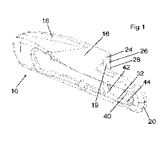
Figures 1 to 4 show a joining device 10 for use in forming a joining assembly
12
for joining two elongate articles 14 to each other.
It will be appreciated that the elongate articles 14 could be separate
articles, such
as two wires, wire ropes, cables, or the like. Alternatively, the elongate
articles 14
could be respective portions of a single elongate article that has been broken
or cut.
Alternatively, the elongate articles 14 may be respective end regions of the
same
elongate article.
8
CA 03184194 2022- 12- 23
WO 2022/003495
PCT/IB2021/055532
The joining assembly 12 is shown in Figures 10 to 19 and comprises first and
second of the joining devices 10 attached to each other. The first and second
joining
devices 10 are identical to each other.
Each joining device 10 comprises a body 16 having a main part 18 and a
substantially flat projecting formation 20. The main part 18 defines an
internal space
19 in which a securing arrangement 46 is provided to secure the elongate
article 14 to
the joining device 10. The securing arrangement 46 is described in detail
below.
Each main part 18 defines a recess 22 to receive the projecting formation 20
of
the other joining device 10. Each main part 18 has an end face 24 extending
diagonally from the recess 22 to the projecting formation 20.
An obtuse angle is defined between the end face 24 and the projecting
formation
20. The end face 24 defines an aperture 26 to provide access to the internal
space
19.
The end face 24 has an edge 28 around the aperture 26. The substantially flat
projecting formation 20 extends from a region of the edge 28. The recess 22 is
defined
in the main part 18 opposite the projecting formation 20.
The first joining device 10 comprises a first attaching arrangement. The
second
joining device 10 comprises a second attaching arrangement. The first and
second
attaching arrangements cooperate with each other to attach the first joining
device 10
to the second joining device 10.
Each of the first and second attaching arrangements comprises a lug 30 on the
main part 18 of the body 16 and a receiving formation in the form of a through
hole 32
defined by the projecting formation 20. The lug 30 extends from the recess 22.
Each lug 30 comprises a support portion 34 and a head 36. The support portion
34 connects the head 36 to the main part 18 of the body 16. The head 36 has a
lip
portion 38, which extends beyond the support portion 34.
9
CA 03184194 2022- 12- 23
WO 2022/003495
PCT/IB2021/055532
Each receiving formation comprises an elongate ledge 40 extending across the
hole 32. Each hole 32 has wide and narrow regions 42, 44. The elongate ledge
40
partially defines the narrow region 44.
The wide region 42 of the hole 32 of each of the joining devices 10 allows the
head 36 of the lug 30 of the other joining device 10 to be inserted
therethrough.
Each narrow region 44 can then receive the support portion 34 of the other
joining
device 10. As a result, each lip portion 38 extends across the ledge 40 of the
other
joining device 10, thereby preventing the lug 30 from being removed from the
hole 32.
When the lug 30 of each joining device 10 is received by the hole 32 of the
other
joining device 10, and the support portions 34 received in the narrow regions
44, both
lip portions 38 extend over the ledges 40. In this position of the lugs 30,
the first and
second joining devices 10 are locked to each other.
Each of the first and second joining devices 10 comprises the securing
arrangement 46 for securing an end region of respective elongate articles 14
to each
joining device 10.
In order to secure the elongate articles 14 to the first and second joining
devices
10, each joining device 10 comprises the securing arrangement 46 in the
internal
space 19 defined by the main part 18 of the body 16.
The main part 18 defines an opening 47 at an end of the main part 18 opposite
the projecting formation 20. The elongate articles can be inserted into the
spaces 19
through the openings 47.
Each securing arrangement 46 has a path 48 along which the end region of the
elongate article 14 can extend. The path 48 is provided adjacent a clamping
formation
in the form of a clamping wall 50. The clamping wall 50 is a wall of the main
part 18.
CA 03184194 2022- 12- 23
WO 2022/003495
PCT/IB2021/055532
A clamping member 52 and an urging member 54 are provided. The clamping
member 52 is in the form of a roller, but it will be appreciated that the
clamping member
52 could be any other type of clamping member 52, such as a wedge.
The urging member 54 is in the form of a spring, and urges the clamping member
52 into the path 48 to clamp the elongate article 14 against the clamping wall
50.
The urging member 54 extends along a reaction formation in the form of a
reaction wall 56. The reaction wall 56 is also a wall of the main part 18.
The reaction wall 56 and the clamping wall 50 converge towards each other,
thereby providing a narrowing gap therebetween.
Each securing arrangement 46 comprises an engaging formation in the form of
a holding arrangement 60 for holding the urging member 54. The holding
arrangement
60 holds the urging member 54 so that it can urge the clamping member 52 into
engagement with the elongate article 14.
The holding arrangement 60 is shown most clearly in Figures 7 and 8. The
holding arrangement 60 is inserted into the space 19 in the main part 18 via
the
aperture 26.
Each holding arrangement 60 comprises a substantially rectangular holder 62
for
holding an end region of the urging member 54. The holding arrangement 60
further
includes an end stop 64 spaced from the holder 62.
The end stop 64 engages the end of the elongate article 14 on insertion of the
elongate article into the main part 18. Thus, the end stop 64 prevents further
insertion
of the elongate article 14 into the body 16.
Two connecting members 68 extend between the end stop 64 and the holder 62.
A gap is defined between the connecting members 68. The gap provides a window
69 through which a user can check whether the elongate article 14 engages the
end
stop 64.
11
CA 03184194 2022- 12- 23
WO 2022/003495
PCT/IB2021/055532
Referring to Figure 9, the aperture 26 allows a user to view the inside of the
main
part 18 and look through the window 69.
The urging member 54 urges the clamping member 52 along the reaction wall
56 towards the clamping wall 50. The clamping member 52 is urged against the
end
region of the elongate article 14 between the reaction wall 56 and the
clamping wall
50.
Clamping of the elongate article 14 occurs by the clamping member 52 being
wedged between the reaction wall 56 and the elongate article 14.
In the position shown, for example in Figure 6, tension applied to the
elongate
article 14 (shown in broken lines) in the direction indicated by the arrow A
pulls the
clamping member 52 further into the narrowing gap, thereby increasing the
clamping
force on the elongate article 14.
Thus, the end region of the elongate article 14 and the clamping member 52 are
clamped between the reaction wall 56 and the clamping wall 50.
Referring to Figures 12 to 17, the joining assembly 12 is shown being
assembled.
Figures 12 and 13 show an end region of each of the elongate articles 14
inserted
through the opening in a respective one of the main parts 18. When so
inserted, the
end regions are clamped by the securing arrangements 46 in the main parts 18.
Figures 14 and 15 show the first and second joining devices 10 being brought
together so that the projecting formation 20 of each joining device 10
overlaps the
main part 18 of the other joining device 10.
The joining devices 10 can be manipulated so that, as shown in Figure 16, the
lug 30 of the first joining device 10 is received by the hole 32 defined by
the projecting
formation 20 of the second joining device 10, and the lug 30 of the second
joining
device 10 is received by the hole 32 defined by the projecting formation 20 of
the first
joining device 10.
12
CA 03184194 2022- 12- 23
WO 2022/003495
PCT/IB2021/055532
In the position shown in Figure 16, the lugs 30 are disposed in the respective
holes 32 so that the support portion 34 extends through the wide regions 42 of
the
holes 32. The wide region 42 of each hole 32 is closer to the main part 18 of
the
respective joining device 10 than the narrow region 44.
Thus, referring to Figure 17, when the lugs 30 are received in the holes 32,
tension in the elongate articles 14 pulls the first and second joining devices
10.
As a result, the support portions 34 of each lug 30 are moved into the narrow
regions 44 of each hole 32, and the lip portions 38 of each lug 30 extend
across the
ledge 40. This has the effect of preventing the lugs 30 from moving out of the
holes
32 and causing the joining devices 10 to be detached from each other.
The embodiment of the joining assembly 12 described herein allows two cut ends
of an elongate article 14 (such as a fence or trellis wire) to be joined
together to
effectively repairing the elongate article 14.
The joining assembly 12 provides the advantage that it provides two large
members on the ends of the elongate articles 14, thereby allowing a person
repairing
the cut elongate article 14 to grip the cut end regions and pull them
together.
Various modifications can be made without departing from the scope of the
invention. For example, the elongate ledge 40 of each joining device 10 may be
provided with a friction formation in the form of a rib 70 extending along the
ledge 40.
Figures 23 and 24 show one of the joining devices 10 that includes the rib 70.
Figure 23 is a top view showing the projecting formation 20 and the rib 70 on
the
ledge 40. Figure 24 is a sectional view through the joining assembly 12,
showing the
interaction between the lug 30 and the rib 70 on the ledge 40.
Specifically, Figure 24 shows the engagement of the lip portion 38 with the
rib
70. The lip portion 38 extends from the support portion 34 across the ledge
40, thereby
engaging the rib 70, as shown in Figure 24.
13
CA 03184194 2022- 12- 23
WO 2022/003495
PCT/IB2021/055532
When the lug 30 of each joining device 10 is received by the hole 32 of the
other
joining device 10, and the support portions 34 received in the narrow regions
44, both
lip portions 38 extend over the ledges 40. In this position, the lip portion
38 of each
joining device 10 engages the rib 70 of the other joining device 10.
When so engaged, each rib 70 presses on the lip portion 38 of the other
joining
device, thereby applying a force on the lip portion to hold the two joining
devices 10
together. As a result, the two joining devices allow a user, e.g. an
installer, to apply
appropriate tension to the elongate articles 14.
14
CA 03184194 2022- 12- 23