Note : Les descriptions sont présentées dans la langue officielle dans laquelle elles ont été soumises.
1
BINDING SYSTEM, METHOD FOR BINDING, AND COMPUTER READABLE
STORAGE MEDIUM STORING PROGRAM
TECHNICAL FIELD
[0001] The present invention relates to a binding system including a binding
machine that
binds reinforcing bars with a wire.
BACKGROUND ART
[0002] Reinforcing bars are used in concrete structures to improve the
strength, and are
bound with wires such that the reinforcing bars do not deviate from a
predetermined position
when concrete is poured.
[0003] In the related art, there has been proposed a binding machine called a
reinforcing
bar binding machine that winds a wire around two or more reinforcing bars, and
twists the
wire wound around the reinforcing bars to bind the two or more reinforcing
bars with the
wire.
[0004] In addition to the binding machine used by being held by hand, as a
reinforcing
mesh manufacturing device, there is known a device in which a plurality of
binding machines
are arranged in two front and rear rows, and a machine is inserted and removed
by being
moved up and down while supplying reinforcing bars, thereby binding the
reinforcing bars
(for example, see JP2013-35052A).
[0005] In a reinforcing mesh manufacturing device in the related art,
information related to
binding, such as information indicating whether reinforcing bars can be
normally bound with
a wire and information for specifying a position of a binding position where
binding has not
been normally performed, is not acquired. As a result, in a reinforcing mesh
having a
plurality of binding positions, it is difficult to search for the binding
related information for
each binding position.
[0006] An object of the present invention is to provide a binding system
capable of
acquiring binding related information and a position of a binding position.
SUMMARY OF INVENTION
[0007] According to an aspect of the present invention, there is provided a
binding system
including: a binding device including a binding machine that binds reinforcing
bars with a
wire, and a transfer robot that moves the binding machine to a binding
position by a relative
CA 3187638 2023-01-19
' ' 2
movement between the binding machine and the reinforcing bars; an information
acquisition
unit configured to acquire binding related information related to an operation
of binding the
reinforcing bars with the wire; and a position information acquisition unit
configured to
acquire position information of the binding position in a manner associable
with the binding
related information for the binding position acquired by the information
acquisition unit.
[0008] In a structure in which a plurality of binding positions are formed,
the position
information for specifying the binding position and the binding related
information in each
binding position may be associated with each other.
BRIEF DESCRIPTION OF DRAWINGS
[0009] Fig. lA is a perspective view illustrating an example of binding
equipment
according to the present embodiment;
Fig. 1B is a perspective view illustrating the example of the binding
equipment
according to the present embodiment;
Fig. 1C is a perspective view illustrating another example of the binding
equipment
according to the present embodiment;
Fig. 2 is a side view illustrating an example of a reinforcing bar binding
machine
according to the present embodiment;
Fig. 3A is a side view illustrating an example of a binding unit;
Fig. 3B is an internal structural view illustrating the example of the binding
unit;
Fig. 3C is a main part plan view illustrating the example of the binding unit;
Fig. 3D is a main part plan view illustrating the example of the binding unit;
Fig. 4A is a block diagram illustrating an example of a control function of
the
binding equipment;
Fig. 4B is a block diagram illustrating an example of a control function of
the
binding equipment;
Fig. 4C is a block diagram illustrating an example of a control function of
the
binding equipment;
Fig. 4D is a block diagram illustrating an example of a control function of
the
binding equipment;
Fig. 5 is a side view illustrating an example of the reinforcing bar binding
machine
including an information acquisition unit;
Fig. 6 is an explanatory view illustrating a reporting example in the
information
CA 3187638 2023-01-19
=
3
processing device based on binding related information acquired by the
information
acquisition unit;
Fig. 7A is a perspective view illustrating another example of the reinforcing
bar
binding machine including the information acquisition unit;
Fig. 7B is a perspective view illustrating another example of the reinforcing
bar
binding machine including the information acquisition unit;
Fig. 8 is a flowchart illustrating an example of an operation based on binding
position image information acquired by image recognition of a binding form;
Fig. 9A is a perspective view illustrating an example of a binding position
bound
with a wire;
Fig. 9B is a perspective view illustrating an example of a binding position
bound
with a wire;
Fig. 9C is a perspective view illustrating an example of a binding position
bound
with a wire;
Fig. 10A is an explanatory view illustrating an example of the binding
position
image information;
Fig. 10B is an explanatory view illustrating an example of the binding
position
image information;
Fig. 11 is an explanatory view illustrating an example of an address for
specifying
the binding position;
Fig. 12A is an explanatory view illustrating an output example of a binding
result;
Fig. 12B is an explanatory view illustrating an output example of the binding
result;
Fig. 13A is a flowchart illustrating an example of an operation of associating
binding result information with position information;
Fig. 13B is a flowchart illustrating an example of the operation of
associating the
binding result information with the position information;
Fig. 13C is a flowchart illustrating an example of the operation of
associating the
binding result information with the position information;
Fig. 13D is a flowchart illustrating an example of the operation of
associating the
binding result information with the position information;
Fig. 13E is a flowchart illustrating an example of the operation of
associating the
binding result information with the position information;
Fig. 14A is a perspective view illustrating an example of binding equipment
CA 3187638 2023-01-19
' .
' 4 '
including a plurality of reinforcing bar binding machines;
Fig. 14B is a perspective view illustrating an example of the binding
equipment
including the plurality of reinforcing bar binding machines;
Fig. 14C is a plan view illustrating an example of the binding equipment
including
the plurality of reinforcing bar binding machines;
Fig. 15 is a flowchart illustrating an example of an operation of associating
the
binding result information with binding machine identification information;
Fig. 16A is a plan view illustrating an example of a binding result obtained
after
binding directions are switched;
Fig. 16B is a main part plan view illustrating an example of the binding
result
obtained after the binding directions are switched;
Fig. 16C is a main part plan view illustrating an example of the binding
result
obtained after the binding directions are switched;
Fig. 17 is a flowchart illustrating an example of an operation based on
reinforcing
bar identification information acquired by image recognition of reinforcing
bars;
Fig. 18A is an explanatory view illustrating an example of binding position
image
information before binding;
Fig. 18B is an explanatory view illustrating an example of the binding
position
image information before binding;
Fig. 19 is a flowchart illustrating an example of an operation based on the
reinforcing bar identification information acquired based on a feed amount of
a wire;
Fig. 20 is a flowchart illustrating an example of an operation based on the
reinforcing bar identification information acquired based on input
information;
Fig. 21A is an explanatory view illustrating an arrangement example of the
reinforcing bars;
Fig. 21B is an explanatory view illustrating an arrangement example of the
reinforcing bars;
Fig. 22 is a flowchart illustrating an example of an operation of determining
a
timing of removing the reinforcing bars from the reinforcing bar binding
machine in a final
stage of a binding operation;
Fig. 23 is a flowchart illustrating an example of an operation of removing
slack of
the wire by moving the reinforcing bar binding machine in a direction
separating from the
reinforcing bars;
CA 3187638 2023-01-19
Fig. 24A is a perspective view illustrating an example of an attachment and
detachment structure of the reinforcing bar binding machine;
Fig. 24B is a perspective view illustrating an example of the attachment and
detachment structure of the reinforcing bar binding machine;
Fig. 25 is an explanatory view illustrating an example of a mode in which the
reinforcing bar binding machine is used alone;
Fig. 26A is a perspective view of the binding equipment according to the
present
embodiment illustrating a modification of the transfer robot;
Fig. 26B is a perspective view of the binding equipment according to the
present
embodiment illustrating a modification of the transfer robot;
Fig. 27A is a flowchart illustrating an example of the binding operation based
on a
remaining amount of the wire;
Fig. 27B is a flowchart illustrating an example of the binding operation based
on the
remaining amount of the wire;
Fig. 28A is a flowchart illustrating an example of an operation of calculating
a
remaining wire amount;
Fig. 28B is a flowchart illustrating an example of the operation of
calculating the
remaining wire amount;
Fig. 28C is a flowchart illustrating an example of the operation of
calculating the
remaining wire amount;
Fig. 29A is a perspective view illustrating a modification of the binding
equipment
according to the present embodiment; and
Fig. 29B is a perspective view illustrating a configuration of main parts of a
reel
accommodation unit.
DESCRIPTION OF EMBODIMENTS
[0010] Hereinafter, an example of binding equipment as an embodiment of a
binding
device of the present invention, and a reinforcing bar binding machine as an
embodiment of a
binding machine used for the binding equipment will be described with
reference to the
drawings.
[0011] <Example of Overall Configuration of Binding Equipment According to
Present
Embodiment>
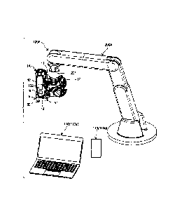
Figs. lA and 1B are perspective views illustrating an example of binding
equipment
CA 3187638 2023-01-19
I 16
according to the present embodiment, and Fig. 1C is a perspective view
illustrating another
example of the binding equipment according to the present embodiment. Binding
equipment
100A illustrated in Figs. 1A and 1B includes: a reinforcing bar binding
machine lA that uses
reinforcing bars S as a target to be bound and an intersection of two
intersecting reinforcing
bars S as a binding position P10, and binds the intersection of the two
intersecting reinforcing
bars S with a wire W; and a transfer robot 200A that moves the reinforcing bar
binding
machine lA to the binding position P10.
[0012] The transfer robot 200A is implemented by, for example, a device called
a robot
arm or the like in which a plurality of arms are rotatably connected via a
shaft, and moves the
reinforcing bar binding machine lA to the binding position P10 by moving the
reinforcing bar
binding machine lA in a direction approaching and a direction separating from
a disposition
plane SF of the reinforcing bars S and in a direction along the disposition
plane SF.
[0013] Binding equipment 100B illustrated in Fig. 1C has a configuration in
which a reel
accommodation unit 21 that accommodates reels 20 around which the wire W is
wound is
independent of the reinforcing bar binding machine 1A, and includes the
reinforcing bar
binding machine 1A, the reel accommodation unit 21 provided corresponding to
the
reinforcing bar binding machine 1A, and a wire drawing mechanism 210 that
draws out the
wire W from the reels 20 accommodated in the reel accommodation unit 21. In
addition, the
binding equipment 100B includes a transfer robot 200B that moves the
reinforcing bar
binding machine lA to the binding position P10.
[0014] The binding equipment 100B moves the binding position P10 to a
predetermined
position facing the reinforcing bar binding machine lA by moving the
reinforcing bars S in
the direction along the disposition plane SF by another transfer robot such as
a transport
mechanism (not illustrated). In addition, the transfer robot 200B moves the
reinforcing bar
binding machine lA to the binding position P10 by moving the reinforcing bar
binding
machine 1A in the direction approaching and the direction separating from the
disposition
plane SF of the reinforcing bars S.
[0015] The reinforcing bar binding machine lA illustrated in Figs. 1A, 1B, and
1C includes
an information acquisition unit 101 as an example of an information
acquisition means that
acquires binding related information related to a binding operation of binding
the reinforcing
bars S with the wire W, such as information indicating presence or absence of
a failure that
hinders the binding operation of binding the reinforcing bars S with the wire
W, information
indicating a state (also referred to as a binding state) of the wire W that
binds the reinforcing
CA 3187638 2023-01-19
7
bars S by the binding operation, information identifying the reinforcing bars
S, and
information identifying a position of the binding position P10. In addition,
the reinforcing
bar binding machine lA includes an information communication unit 102 that
notifies an
information processing device 110 (110a and 110b) such as a personal computer,
a
smartphone, or a tablet of the binding related information acquired by the
information
acquisition unit 101. The information communication unit 102 implemented by,
for
example, a wireless communication chip including an antenna, a transmission
circuit, a
reception circuit, and the like.
[0016] <Example of Configuration of Reinforcing Bar Binding Machine According
to
Present Embodiment>
Fig. 2 is a side view illustrating an example of the reinforcing bar binding
machine
according to the present embodiment. The reinforcing bar binding machine lA is
an
example of a binding machine, and binds the intersection of the two
intersecting reinforcing
bars S with the wire W. In this example, the wire W is wound around the
intersection of the
two reinforcing bars S by an operation of feeding the wire W in a forward
direction indicated
by an arrow F, the wire W wound around the reinforcing bars S is cut after
being wrapped
around the reinforcing bars S by an operation of feeding the wire W in a
reverse direction
indicated by an arrow R, then the wire W is twisted, and the intersection of
the two
reinforcing bars S is bound with the wire W.
[0017] In order to realize the above-described functions, the reinforcing bar
binding
machine 1A includes a magazine 2 in which the wire W is accommodated, a wire
feeding unit
3 that feeds the wire W in the forward direction and the reverse direction,
and wire guides 4
that guide the wire W fed by the wire feeding unit 3. In addition, the
reinforcing bar binding
machine lA includes a curl forming unit 5 constituting a path through which
the wire W fed
.. by the wire feeding unit 3 is wound around the reinforcing bars S, and a
cutting unit 6 that
cuts the wire W wrapped around the reinforcing bars S. Further, the
reinforcing bar binding
machine 1A includes a binding unit 7 that twists the wire W wrapped around the
reinforcing
bars S, and a driving unit 8 that drives the binding unit 7.
[0018] The magazine 2 is an example of an accommodation unit, and a reel 20,
around
.. which an elongated wire W is wound so as to be able to be unwound, is
rotatably and
detachably accommodated therein. As the wire W, a wire formed of a plastically
deformable
metal wire, a wire obtained by coating a metal wire with a resin, or a twisted
wire is used.
[0019] In a configuration in which the reinforcing bars S are bound with a
single wire W,
CA 3187638 2023-01-19
'8
the single wire W is wound around a hub portion (not illustrated) of the reel
20, and the single
wire W can be drawn out while the reel 20 rotates. In addition, in a
configuration in which
the reinforcing bars S are bound with a plurality of wires W, the plurality of
wires W are
wound around the hub portion, and the plurality of wires W can be
simultaneously drawn out
while the reel 20 rotates. For example, in a configuration in which the
reinforcing bars S are
bound with two wires W, the two wires W are wound around the hub portion, and
the two
wires W can be simultaneously drawn out while the reel 20 rotates.
[0020] In the reinforcing bar binding machine 1A illustrated in Fig. 1C, since
the reel
accommodation unit 21 that accommodates the reels 20 around which the wire W
is wound
has a configuration independent of the reinforcing bar binding machine 1A, the
magazine 2
may not be provided. Similarly, in the reinforcing bar binding machine lA
illustrated in
Figs. 1A and 1B, the magazine 2 that accommodates the reel 20 may be
implemented to be
independent of the reinforcing bar binding machine 1A, and a form of the
magazine 2
independent of the reinforcing bar binding machine lA is not limited to a form
illustrated in
Fig. 2. Further, in the reinforcing bar binding machine lA in which the
reinforcing bars S
are bound with a plurality of wires W, in a configuration in which the reel
accommodation
unit 21 (magazine 2) is independent of the reinforcing bar binding machine 1A,
a plurality of
reels 20 around which a single wire W is wound may be accommodated in the reel
accommodation unit 21 (magazine 2), and the wire W may be simultaneously drawn
out from
the respective reels 20, so that the plurality of wires W may be supplied to
the reinforcing bar
binding machine 1A.
[0021] The wire feeding unit 3 includes a pair of feeding gears 30 that clamp
and feed the
wire W. In the wire feeding unit 3, as a rotation operation of a feed motor 31
(see Figs. 4A,
4B, 4C, and 4D) is transmitted, the feeding gears 30 rotate. As a result, the
wire feeding unit
3 feeds the wire W clamped between the pair of feeding gears 30 along an
extending direction
of the wire W. In a configurations in which a plurality of, for example, two
wires W are fed
to bind the reinforcing bars S, the two wires W are fed in a state of being
arranged in parallel.
[0022] In the wire feeding unit 3, by switching forward and reverse of a
rotation direction
of the feed motor 31, a rotation direction of the feeding gears 30 is
switched, and forward and
.. reverse of a feeding direction of the wire W is switched, whether to feed
the wire W in the
forward direction indicated by the arrow F, or feed the wire W in the reverse
direction
indicated by the arrow R.
[0023] The wire guides 4 are provided at predetermined positions on an
upstream side and
CA 3187638 2023-01-19
a downstream side of the wire feeding unit 3 with respect to the feeding
direction in which the
wire W is fed in the forward direction. In the configuration in which the two
wires W are
fed to bound the reinforcing bars S, the wire guide 4 provided on the upstream
side of the
wire feeding unit 3 regulates orientations of the two wires W in a radial
direction, and guides
the two entered wires W between the pair of feeding gears 30 in parallel. The
wire guide 4
provided on the downstream side of the wire feeding unit 3 regulates the
orientations of the
two wires W in the radial direction, and guides the two entered wires W to the
cutting unit 6
and the curl forming unit 5 in parallel.
[0024] The curl forming unit 5 includes a curl guide 50 that imparts a winding
habit to the
wire W fed by the wire feeding unit 3, and a leading guide 51 that leads, to
the binding unit 7,
the wire W imparted with the winding habit by the curl guide 50. In the
reinforcing bar
binding machine 1A, the path of the wire W fed by the wire feeding unit 3 is
regulated by the
curl forming unit 5, so that a trajectory of the wire W becomes a loop Ru as
indicated by a
chain double-dashed line in Fig. 2, and the wire W is wound around the
reinforcing bars S.
[0025] The cutting unit 6 has a configuration in which the wire W is cut by a
relative
operation of a pair of blade portions, and in this example, includes a fixed
blade portion 60
and a movable blade portion 61 that rotates about the fixed blade portion 60
which serves as a
fulcrum axis. In the cutting unit 6, an operation of the binding unit 7 is
transmitted to the
movable blade portion 61 via a transmission member 62, and the cutting unit 6
cuts the wire
W sandwiched between the fixed blade portion 60 and the movable blade portion
61 by a
rotation operation of the movable blade portion 61.
[0026] The binding unit 7 includes a locking member 70 that locks the wire W
and a sleeve
71 that causes the locking member 70 to operate. The driving unit 8 includes a
motor 80 and
a reduction gear 81 that performs speed reduction and torque amplification.
[0027] When the binding unit 7 is driven by the driving unit 8, the sleeve 71
causes the
locking member 70 to operate so as to lock the wire W. In addition, the
binding unit 7 binds
the reinforcing bars S by twisting the wire W after the operation of the
sleeve 71 is
transmitted to the movable blade portion 61 via the transmission member 62 and
the cutting
unit 6 cuts the wire W in conjunction with the operation of the sleeve 71.
[0028] In the reinforcing bar binding machine 1A, the wire feeding unit 3, the
wire guides
4, the cutting unit 6, the binding unit 7, the driving unit 8, and the like
are accommodated
inside a main body portion 10. In the reinforcing bar binding machine 1A, the
binding unit 7
is provided inside a front end side (also referred to as a front side) which
is one end portion
CA 3187638 2023-01-19
.10
along an extending direction of the main body portion 10, and the driving unit
8 is provided
inside a rear end side (also referred to as a rear side) which is the other
end portion thereof.
[0029] In addition, in the reinforcing bar binding machine 1A, the curl guide
50 and the
leading guide 51 of the curl forming unit 5 are provided at an end portion of
the front side of
the main body portion 10. In the reinforcing bar binding machine 1A, a portion
between the
curl guide 50 and the leading guide 51 serves as an introduction portion 18
where the
reinforcing bars S are placed. Further, in the reinforcing bar binding machine
1A, an
abutting portion 16 against which the reinforcing bars S placed into the
introduction portion
18 abuts is provided between the curl guide 50 and the leading guide 51 at the
end portion of
the front side of the main body portion 10.
[0030] Further, in a case where the reinforcing bar binding machine lA is
applied in a form
to be used by being held by hand of an operator, a handle portion 11 which can
be operated by
being held by hand is provided in the main body portion 10. In the reinforcing
bar binding
machine 1A, the handle portion 11 extends downward from the main body portion
10, and a
battery attachment portion 17 to which a battery 15 is attachably and
detachably attached is
provided at a lower portion of the handle portion 11. In addition, in the
reinforcing bar
binding machine 1A, the magazine 2 is provided in front of the handle portion
11.
[0031] In the case where the reinforcing bar binding machine 1A is applied in
a form to be
used by being held by hand of an operator, a trigger 12 is provided on the
front side of the
handle portion 11, and a switch 13 is provided inside the handle portion 11.
In the
reinforcing bar binding machine 1A, the control unit 14 controls the motor 80
and the feed
motor 31 in accordance with a state of the switch 13 pressed with an operation
of the trigger
12. The control unit 14 is implemented by, for example, a Micro
controller unit (MCU)
including a processor, a memory, an interface, and the like.
[0032] Incidentally, since the reinforcing bar binding machine lA used in the
binding
equipment 100A and the binding equipment 100B includes the trigger 12, an
operation
confirmation can be performed by the reinforcing bar binding machine lA alone
without
performing control by the information processing device 110a. However, the
reinforcing bar
binding machine lA used in the binding equipment 100A and the binding
equipment 100B
may be implemented not to include the trigger 12 and the switch 13.
[0033] Fig. 3A is a side view illustrating an example of the binding unit,
Fig. 3B is an
internal structural view illustrating the example of the binding unit, and
Figs. 3C and 3D are
main part plan views illustrating the example of the binding unit.
CA 3187638 2023-01-19
. . ,
11
[0034] Next, the example of the binding unit according to the present
embodiment will be
described with reference to the drawings. The binding unit 7 includes a
rotation shaft 72 that
moves the sleeve 71 and causes the sleeve 71 to rotate so as to cause the
locking member 70
to operate. In the binding unit 7 and the driving unit 8, the rotation shaft
72 and the motor
80 are connected to each other via the reduction gear 81, and the rotation
shaft 72 is driven by
the motor 80 via the reduction gear 81.
[0035] The locking member 70 includes a center hook 70C connected to the
rotation shaft
72, and a first side hook 70R and a second side hook 70L that open and close
with respect to
the center hook 70C.
[0036] In the binding unit 7, a side on which the center hook 70C, the first
side hook 70R,
and the second side hook 70L are provided is referred to as a front side, and
a side on which
the rotation shaft 72 is connected to the reduction gear 81 is referred to as
a rear side.
[0037] The center hook 70C is connected to a front end, which is one end
portion of the
rotation shaft 72, via a configuration that is rotatable with respect to the
rotation shaft 72,
rotatable integrally with the rotation shaft 72, and movable in an axial
direction integrally
with the rotation shaft 72.
[0038] A front end side of the first side hook 70R, which is one end portion
thereof along
the axial direction of the rotation shaft 72, is located on one side portion
with respect to the
center hook 70C. In addition, a rear end side of the first side hook 70R,
which is the other
end portion thereof along the axial direction of the rotation shaft 72, is
rotatably supported on
the center hook 70C by a shaft 71b.
[0039] A front end side of the second side hook 70L, which is one end portion
thereof
along the axial direction of the rotation shaft 72, is located on the other
side portion with
respect to the center hook 70C. In addition, a rear end side of the second
side hook 70L,
which is the other end portion thereof along the axial direction of the
rotation shaft 72, is
rotatably supported on the center hook 70C via the shaft 71b.
[0040] As a result, in the locking member 70, the front end side of the first
side hook 70R
opens and closes in a direction in which the front end side is separated from
and brought into
contact with the center hook 70C by a rotation operation about the shaft 71b
as a fulcrum. In
addition, the front end side of the second side hook 70L opens and closes in a
direction in
which the front end side is separated from and brought into contact with the
center hook 70C.
[0041] The sleeve 71 has a shape in which a range of a predetermined length
along the
axial direction of the rotation shaft 72 from an end portion in a forward
direction indicated by
CA 3187638 2023-01-19
.12
an arrow Al is divided into two ranges in a radial direction, and the first
side hook 70R and
the second side hook 70L are inserted. In addition, the sleeve 71 has a
tubular shape
covering the periphery of the rotation shaft 72, and has a convex portion (not
illustrated)
protruding from an inner peripheral surface of a tubular space into which the
rotation shaft 72
is inserted. The convex portion enters a groove portion of a feed screw 72a
formed along the
axial direction on an outer periphery of the rotation shaft 72.
[0042] When the rotation shaft 72 rotates, the sleeve 71 moves in a front-rear
direction,
which is a direction along the axial direction of the rotation shaft 72, in
accordance with a
rotation direction of the rotation shaft 72 by an action of the convex portion
(not illustrated)
and the feed screw 72a of the rotation shaft 72. When the sleeve 71 moves to
an end portion
in a forward direction of the feed screw 72a along the axial direction of the
rotation shaft 72,
the sleeve 71 rotates integrally with the rotation shaft 72.
[0043] The sleeve 71 includes an opening and closing pin 71a that opens and
closes the
first side hook 70R and the second side hook 70L. The first side hook 70R
includes an
opening and closing guide hole 73R into which the opening and closing pin 71a
is inserted,
and the second side hook 70L includes an opening and closing guide hole 73L
into which the
opening and closing pin 71a is inserted.
[0044] The opening and closing guide holes 73R and 73L are formed by grooves
extending
along a moving direction of the sleeve 71. The opening and closing guide hole
73R has a
shape in which a movement in a linear direction of the opening and closing pin
71a that
moves in conjunction with the sleeve 71 is converted into an opening and
closing operation
by rotation of the first side hook 70R with the shaft 71b as a fulcrum. The
opening and
closing guide hole 73L has a shape in which the movement in the linear
direction of the
opening and closing pin 71a that moves in conjunction with the sleeve 71 is
converted into an
opening and closing operation by rotation of the second side hook 70L with the
shaft 71b as a
fulcrum.
[0045] When the sleeve 71 moves to the rear side indicated by an arrow A2, the
first side
hook 70R and the second side hook 70L move in a direction separating from the
center hook
70C by the rotation operation with the shaft 71b as a fulcrum due to a
trajectory of the
opening and closing pin 71a and the shapes of the opening and closing guide
holes 73R and
73L.
[0046] As a result, the first side hook 70R and the second side hook 70L are
opened with
respect to the center hook 70C, and a feed path through which the wire W
passes is formed
CA 3187638 2023-01-19
13
between the first side hook 70R and the center hook 70C and between the second
side hook
70L and the center hook 70C.
[0047] In a state where the first side hook 70R and the second side hook 70L
are opened
with respect to the center hook 70C, the wire W fed in the forward direction
by the wire
feeding unit 3 passes through between the center hook 70C and the first side
hook 70R. The
wire W passing through between the center hook 70C and the first side hook 70R
is led to the
curl forming unit 5. Then, the wire W to which the winding habit is imparted
by the curl
guide 50 of the curl forming unit 5 and which is led to the binding unit 7 by
the leading guide
51 passes through between the center hook 70C and the second side hook 70L.
[0048] When the sleeve 71 moves to the front side indicated by the arrow Al,
the first side
hook 70R and the second side hook 70L move in a direction approaching the
center hook 70C
by the rotation operation with the shaft 71b as a fulcrum due to the
trajectory of the opening
and closing pin 71a and the shapes of the opening and closing guide holes 73R
and 73L. As
a result, the first side hook 70R and the second side hook 70L are closed with
respect to the
center hook 70C.
[0049] When the first side hook 70R is closed with respect to the center hook
70C, the wire
W sandwiched between the first side hook 70R and the center hook 70C is locked
in a form of
capable of moving between the first side hook 70R and the center hook 70C. In
addition,
when the second side hook 70L is closed with respect to the center hook 70C,
the wire W
sandwiched between the second side hook 70L and the center hook 70C is locked
in a form of
not coming off from between the second side hook 70L and the center hook 70C.
[0050] In an operation of feeding the wire W wound around the reinforcing bars
S in the
reverse direction by the wire feeding unit 3, a portion sandwiched between the
second side
hook 70L and the center hook 70C is positioned on the upstream side in a
feeding direction of
the wire W, and the portion sandwiched between the first side hook 70R and the
center hook
70C is positioned on the downstream side in the feeding direction of the wire
W.
[0051] As a result, the wire W wound around the periphery of the reinforcing
bars S is
wrapped around the reinforcing bars S with a diameter of the loop Ru reduced
by pulling the
portion sandwiched between the first side hook 70R and the center hook 70C
toward a wire
feeding unit 3 direction by the operation of feeding the wire W in the reverse
direction by the
wire feeding unit 3.
[0052] The sleeve 71 includes a bent portion 71c1 that forms the wire W into a
predetermined shape by pressing and bending the front end side of the wire W
in a
CA 3187638 2023-01-19
14
predetermined direction from the portion sandwiched between the second side
hook 70L and
the center hook 70C, the front end side being one end portion of the wire W
wrapped around
the reinforcing bars S. In addition, the sleeve 71 includes a bent portion
71c2 that forms the
wire W into a predetermined shape by pressing and bending a terminal end side
of the wire W
in a predetermined direction, the terminal end side being the other end
portion of the wire W
which is wrapped around the reinforcing bars S and cut by the cutting unit 6.
The bent
portion 71c1 and the bent portion 71c2 are formed at an end portion of the
sleeve 71 in the
forward direction indicated by the arrow Al.
[0053] When the sleeve 71 moves in the forward direction indicated by the
arrow Al, the
front end side of the wire W locked by the center hook 70C and the second side
hook 70L is
pressed by the bent portion 71c1 and bent toward a reinforcing bar S side. In
addition, when
the sleeve 71 moves in the forward direction indicated by the arrow Al, the
terminal end side
of the wire W which is locked by the center hook 70C and the first side hook
70R and cut by
the cutting unit 6 is pressed by the bent portion 71c2 and bent toward the
reinforcing bar S
side.
[0054] The binding unit 7 includes a rotation regulating unit 74 that
regulates rotations of
the locking member 70 and the sleeve 71 in conjunction with the rotation
operation of the
rotation shaft 72. The rotation regulating unit 74 includes a rotation
regulating blade 74a in
the sleeve 71, and includes a rotation regulating claw (not illustrated) to
which the rotation
regulating blade 74a is locked in the main body portion 10.
[0055] The rotation regulating blade 74a is implemented by providing, at
predetermined
intervals in a circumferential direction of the sleeve 71, a plurality of
convex portions
protruding in the radial direction from an outer periphery of the sleeve 71.
The rotation
regulating blade 74a is fixed to the sleeve 71, and moves and rotates
integrally with the sleeve
71.
[0056] In the rotation regulating unit 74, the rotation regulating blade 74a
is locked in an
operation region where the wire W is locked by the locking member 70, the wire
W is
wrapped around the reinforcing bar S and then cut, and further the wire W is
bent and molded
by the bent portions 71c1 and 71c2 of the sleeve 71. When the rotation
regulating blade 74a
is locked, the rotation of the sleeve 71 in conjunction with the rotation of
the rotation shaft 72
is regulated, and the sleeve 71 moves in the front-rear direction by the
rotation operation of
the rotation shaft 72.
[0057] In addition, in the rotation regulating unit 74, locking of the
rotation regulating
CA 3187638 2023-01-19
15
blade 74a is released in an operation region where the wire W locked by the
locking member
70 is twisted. When the locking of the rotation regulating blade 74a is
released, the sleeve
71 rotates in conjunction with the rotation of the rotation shaft 72. In the
locking member
70, the center hook 70C, the first side hook 70R, and the second side hook 70L
that lock the
wire W rotate in conjunction with the rotation of the sleeve 71.
[0058] <Example of Binding Operation of Reinforcing Bar Binding Machine
According to
Present Embodiment>
Next, an operation of binding the reinforcing bars S with the wire W by the
reinforcing bar binding machine lA according to the present embodiment will be
described
with reference to the drawings.
[0059] In the reinforcing bar binding machine 1A, a state in which the wire W
is clamped
between the pair of feeding gears 30, and the front end of the wire W is
positioned between
the clamped position of the feeding gears 30 and the fixed blade portion 60 of
the cutting unit
6 is a standby state. In addition, in the reinforcing bar binding machine 1A,
in the standby
state, the sleeve 71 and the first side hook 70R, the second side hook 70L,
and the center hook
70C that are attached to the sleeve 71 are moved in a rear direction indicated
by the arrow A2,
and as illustrated in Fig. 3C, the first side hook 70R is opened with respect
to the center hook
70C, and the second side hook 70L is opened with respect to the center hook
70C.
[0060] When the feed motor 31 is driven in a forward rotation direction from
the standby
state, the wire W is fed in a forward direction indicated by an arrow F by the
wire feeding unit
3. In a case of a configuration in which a plurality of, for example, two
wires W are fed, the
two wires W are fed by the wire guides 4 in a state of being arranged in
parallel along the
axial direction of the loop Ru formed by the wires W.
[0061] The wire W fed in the forward direction passes through between the
center hook
70C and the first side hook 70R and is fed to the curl guide 50 of the curl
forming unit 5. By
passing through the curl guide 50, the wire W is imparted with a winding habit
of being
wound around the reinforcing bars S placed in the introduction portion 18
between the curl
guide 50 and the leading guide 51.
[0062] The wire W to which the winding habit is imparted by the curl guide 50
is led by the
leading guide 51 and is further fed in the forward direction by the wire
feeding unit 3, so that
the wire W is led between the center hook 70C and the second side hook 70L by
the leading
guide 51. When the wire W is fed to a predetermined position, driving of the
feed motor 31
is stopped.
CA 3187638 2023-01-19
16
[0063] After feeding of the wire W in the forward direction is stopped, the
motor 80 is
driven in a forward rotation direction. In the sleeve 71, in an operation
region where the
wire W is locked by the locking member 70, rotation of the sleeve 71 in
conjunction with the
rotation of the rotation shaft 72 is regulated by locking the rotation
regulating blade 74a. As
a result, rotation of the motor 80 is converted into a linear movement, and
the sleeve 71
moves in an arrow Al direction which is the forward direction.
[0064] In the locking member 70, when the sleeve 71 moves in the forward
direction
indicated by the arrow Al, the first side hook 70R and the second side hook
70L move in a
direction approaching the center hook 70C by the rotation operation with the
shaft 71b as a
fulcrum due to the trajectory of the opening and closing pin 71a and the
shapes of the opening
and closing guide holes 73R and 73L.
[0065] As a result, as illustrated in Fig. 3D, the first side hook 70R and the
second side
hook 70L are closed with respect to the center hook 70C.
[0066] When the first side hook 70R is closed with respect to the center hook
70C, the wire
W sandwiched between the first side hook 70R and the center hook 70C is locked
in the form
of capable of moving between the first side hook 70R and the center hook 70C.
[0067] On the other hand, when the second side hook 70L is closed with respect
to the
center hook 70C, the wire W sandwiched between the second side hook 70L and
the center
hook 70C is locked in the form of not coming off from between the second side
hook 70L and
.. the center hook 70C.
[0068] In an operation of closing the first side hook 70R and the second side
hook 70L, the
sleeve 71 is moved forward to a position where the wire W is locked, and then
the rotation of
the motor 80 is temporarily stopped, and the feed motor 31 is driven in a
reverse rotation
direction.
[0069] As a result, the pair of feeding gears 30 rotates in the reverse
direction, and the wire
W clamped between the pair of feeding gears 30 is fed in the reverse direction
indicated by
the arrow R. Since the front end side of the wire W is locked in the form of
not coming off
from between the second side hook 70L and the center hook 70C, the wire W is
wrapped
around the reinforcing bars S by the operation of feeding the wire W in the
reverse direction.
[0070] After the wire W is wrapped around the reinforcing bars S and driving
of the feed
motor 31 in the reverse rotation direction is stopped, the motor 80 is driven
in the forward
rotation direction to further move the sleeve 71 in the forward direction
indicated by the
arrow Al.
CA 3187638 2023-01-19
17
[0071] When the operation of the sleeve 71 moving in the forward direction is
transmitted
to the cutting unit 6 by the transmission member 62, the movable blade portion
61 rotates, and
the wire W locked by the first side hook 70R and the center hook 70C is cut by
operations of
the fixed blade portion 60 and the movable blade portion 61.
[0072] By driving the motor 80 in the forward rotation direction, the sleeve
71 is moved in
the forward direction indicated by the arrow Al, and as described above, the
wire W is cut,
and the bent portions 71c1 and 71c2 move in the direction approaching the
reinforcing bars S
substantially at the same time. As a result, the front end side of the wire W
locked by the
center hook 70C and the second side hook 70L is pressed toward the reinforcing
bar S side by
the bent portion 71c1, and is bent toward the reinforcing bar S side with a
locking position as
a fulcrum. When the sleeve 71 further moves in the forward direction, the wire
W locked
between the second side hook 70L and the center hook 70C is maintained in a
state of being
sandwiched by the bent portion 71c1.
[0073] In addition, the terminal end side of the wire W which is locked by the
center hook
70C and the first side hook 70R and cut by the cutting unit 6 is pressed
toward the reinforcing
bar S side by the bent portion 71c2, and is bent toward the reinforcing bar S
side with the
locking position as a fulcrum. When the sleeve 71 further moves in the forward
direction,
the wire W locked between the first side hook 70R and the center hook 70C is
maintained in a
state of being sandwiched by the bent portion 71c2.
[0074] After the front end side and the terminal end side after cutting of the
wire W are
bent toward the reinforcing bars S side, when the motor 80 is further driven
in the forward
rotation direction, the sleeve 71 further moves in the forward direction. When
the sleeve 71
moves to a predetermined position and reaches the operation region where the
wire W locked
by the locking member 70 is twisted, the locking of the rotation regulating
blade 74a is
released.
[0075] Accordingly, when the motor 80 is further driven in the forward
rotation direction,
the sleeve 71 rotates in conjunction with the rotation shaft 72, and the wire
W locked by the
locking member 70 is twisted.
[0076] When it is detected that a load applied to the motor 80 is maximized by
twisting the
wire W, a normal rotation of the motor 80 is stopped. Next, when the motor 80
is driven in
the reverse rotation direction, the rotation shaft 72 rotates in the reverse
direction, and when
the sleeve 71 rotates in the reverse direction following the reverse rotation
of the rotation
shaft 72, the rotation regulating blade 74a is locked, and thus the rotation
of the sleeve 71 in
CA 3187638 2023-01-19
, . 18
conjunction with the rotation of the rotation shaft 72 is regulated. As a
result, the sleeve 71
moves in an arrow A2 direction which is the rear direction.
[0077] When the sleeve 71 moves in the rear direction, the bent portions 71c1
and 71c2 are
separated from the wire W, and maintenance of the wire W by the bent portions
71c1 and
71c2 is released. In addition, when the sleeve 71 moves in the rear direction,
the opening
and closing pin 71a passes through the opening and closing guide holes 73R and
73L. As a
result, the first side hook 70R moves in a direction separating from the
center hook 70C by
the rotation operation with the shaft 71b as a fulcrum. In addition, the
second side hook 70L
moves in a direction separating from the center hook 70C by the rotation
operation with the
shaft 71b as a fulcrum. As a result, the wire W is removed from the locking
member 70.
[0078] <Example of Control Function of Binding Equipment According to Present
Embodiment>
Figs. 4A, 4B, 4C, and 4D are block diagrams illustrating examples of control
functions of the binding equipment. In the binding equipment 100A illustrated
in Fig. lA
and the like, in the example of the control function illustrated in Fig. 4A,
the information
processing device 110a that controls the transfer robot 200A is connected to
the transfer robot
200A and the reinforcing bar binding machine lA attached to the transfer robot
200A such
that transmission and reception of signals and the like for controlling the
transfer robot 200A
and the reinforcing bar binding machine lA are possible.
[0079] In addition, in the binding equipment 100B illustrated in Fig. 1C and
the like, in the
example of the control function illustrated in Fig. 4A, the information
processing device 110a
that controls the transfer robot 200B is connected to the transfer robot 200B
and the
reinforcing bar binding machine 1A attached to the transfer robot 200B such
that transmission
and reception of signals and the like for controlling the transfer robot 200B
and the
reinforcing bar binding machine lA are possible.
[0080] Further, in the binding equipment 100A and 100B, the information
communication
unit 102 of the reinforcing bar binding machine lA is connected to a
communication network
300 such as a cloud such that transmission and reception of the binding
related information
and the like acquired by the information acquisition unit 101 of the
reinforcing bar binding
machine lA are possible.
[0081] In addition, in the binding equipment 100A and 100B, the information
processing
device 110b to which the binding related information acquired by the
information acquisition
unit 101 of the reinforcing bar binding machine lA is notified is connected to
the
CA 3187638 2023-01-19
19
communication network 300 such that transmission and reception of the binding
related
information and the like are possible.
[0082] In the binding equipment 100A and 100B illustrated in Fig. 4B, the
information
processing device 110a is connected to the transfer robots 200A and 200B and
to the
reinforcing bar binding machine IA via the transfer robots 200A and 200B, the
information
processing device 110b is connected to the communication network 300, the
information
communication unit 102 of the reinforcing bar binding machine lA is not
connected to the
communication network 300, and the information processing device 110b is
connected to the
information communication unit 102 of the reinforcing bar binding machine 1A
such that
transmission and reception of the binding related information and the like are
possible.
[0083] In the binding equipment 100A and 100B illustrated in Fig. 4C, the
information
processing device 110a is connected to the transfer robots 200A and 200B and
to the
reinforcing bar binding machine 1A via the transfer robots 200A and 200B, the
information
processing device 110b is connected to the communication network 300 and the
information
communication unit 102 of the reinforcing bar binding machine 1A, the
information
communication unit 102 of the reinforcing bar binding machine 1A is not
connected to the
communication network 300, and the information processing device 110b is
connected to the
information processing device 110a such that transmission and reception of the
binding
related information and the like are possible.
[0084] In the binding equipment 100A and 100B illustrated in Fig. 4D, the
information
processing device 110a that controls the transfer robots 200A and 200B has the
function of the
information processing device 110b to which the binding related information
acquired by the
information acquisition unit 101 of the reinforcing bar binding machine lA is
notified, and the
information processing device 110a is connected to the transfer robots 200A
and 200B and to
the reinforcing bar binding machine 1A via the transfer robots 200A and 200B,
and is
connected to the communication network 300 and the information communication
unit 102 of
the reinforcing bar binding machine 1A.
[0085] In the binding equipment 100A, the information processing device 110a
controls the
transfer robot 200A according to a predetermined program to move the
reinforcing bar
binding machine lA to the binding position P10. In the binding equipment 100B,
the
information processing device 110a controls the transfer robot 200B according
to a
predetermined program to move the reinforcing bar binding machine lA to the
binding
position P10. In addition, in the binding equipment 100A, when the reinforcing
bar binding
CA 3187638 2023-01-19
, . .
machine 1A is moved to the binding position P10, the information processing
device 110a
controls the reinforcing bar binding machine lA according to a predetermined
program, and
outputs a signal for causing the reinforcing bar binding machine lA to perform
an operation
of binding the reinforcing bars S. In the reinforcing bar binding machine 1A,
when a signal
5 of performing the operation of binding the reinforcing bars S is input,
the control unit 14
controls the motor 80 and the feed motor 31 to perform the above-described
series of
operations of binding the reinforcing bars S with the wire W.
[0086] According to a mode in which the reinforcing bar binding machine 1A is
used
alone, the control unit 14 controls, in accordance with the state of the
switch 13 pressed by the
10 operation of the trigger 12 illustrated in Fig. 2, the motor 80 and the
feed motor 31, to perform
the series of operations of binding the reinforcing bars S with the wire W.
[0087] In the reinforcing bar binding machine 1A, the information acquisition
unit 101
acquires the binding related information related to the binding operation of
binding the
reinforcing bars S with the wire W, and the control unit 14 notifies the
information processing
15 device 110b of the binding related information acquired by the
information acquisition unit
101 through the information communication unit 102. In a configuration
illustrated in Fig.
4A, the reinforcing bar binding machine 1A notifies the communication network
300 such as
a cloud of the binding related information acquired by the information
acquisition unit 101
through the information communication unit 102. The information processing
device 110b
20 acquires the binding related information from the communication network
300. In
configurations illustrated in Figs. 4B and 4C, the reinforcing bar binding
machine 1A notifies
the information processing device 110b of the binding related information
acquired by the
information acquisition unit 101 through the information communication unit
102. In a
configuration illustrated in Fig. 4D, the reinforcing bar binding machine 1A
notifies the
information processing device 110a of the binding related information acquired
by the
information acquisition unit 101 through the information communication unit
102.
[0088] The information processing device 110b illustrated in Figs. 4A, 4B, and
4C
performs reporting based on the binding related information acquired by the
information
acquisition unit 101 of the reinforcing bar binding machine 1A. As illustrated
in Fig. 4D, in
a case where the information processing device 110a has the function of the
information
processing device 110b, the information processing device 110a performs the
reporting based
on the binding related information acquired by the information acquisition
unit 101 of the
reinforcing bar binding machine 1A and performs control of the reinforcing bar
binding
CA 3187638 2023-01-19
21
machine 1A and the transfer robots 200A and 200B. The control of the
reinforcing bar
binding machine lA and the transfer robots 200A and 200B based on the binding
related
information acquired by the information acquisition unit 101 provided in the
reinforcing bar
binding machine lA is also referred to as feedback control.
.. [0089] The binding related information is, for example, information
necessary for
determining whether the binding operation can be performed, information
necessary for
determining whether the binding is normally performed, information necessary
for specifying
the position of the binding position P10, information necessary for
identifying the reinforcing
bars S to be bound, information for determining the remaining amount of the
wire W, and the
.. like. In addition, the binding related information is information such as a
current value of
the motor 80, a control signal of the feed motor 31, the number of times of
detection of
various abnormalities, and the number of times of binding.
[0090] The information processing device 110b illustrated in Figs. 4A, 4B, and
4C reports
the binding related information acquired from the reinforcing bar binding
machine 1A. The
information processing device 110b illustrated in Figs. 4A, 4B, and 4C may
determine
whether the binding operation can be performed based on the binding related
information
acquired from the reinforcing bar binding machine 1A, and report binding
availability
information indicating whether the binding operation can be performed.
[0091] In addition, the information processing device 110b illustrated in
Figs. 4A, 4B, and
4C may determine a binding result indicating whether the binding is normally
performed
based on the binding related information acquired from the reinforcing bar
binding machine
1A, and report binding result information indicating the binding result.
[0092] Further, the information processing device 110b illustrated in Figs.
4A, 4B, and 4C
may specify a position of the binding position P10 based on the binding
related information
.. acquired from the reinforcing bar binding machine 1A, and report position
information for
specifying the position of the binding position P10.
[0093] In addition, the information processing device 110b illustrated in
Figs. 4A, 4B, and
4C may identify a diameter, a combination, or the like of the reinforcing bars
S to be bound
based on the binding related information acquired from the reinforcing bar
binding machine
.. 1A, and report reinforcing bar identification information.
[0094] Further, the information processing device 110b illustrated in Figs.
4A, 4B, and 4C
may report the binding result information and the position information
(address) of the
binding position P10 in association with each other.
CA 3187638 2023-01-19
22
[0095] In addition, the information processing device 110b illustrated in
Figs. 4A, 4B, and
4C may determine the remaining amount of the wire W based on the binding
related
information acquired from the reinforcing bar binding machine lA or the reel
accommodation
unit 21, and report wire remaining amount information.
[0096] The information processing device 110b illustrated in Fig. 4C notifies
the
information processing device 110a of the binding related information acquired
from the
reinforcing bar binding machine 1A. The information processing device 110a
illustrated in
Fig. 4C reports the binding related information notified from the information
processing
device 110b.
[0097] The information processing device 110a illustrated in Fig. 4C may
determine
whether the binding operation can be performed based on the binding related
information
notified from the information processing device 110b, and report binding
availability
information indicating whether the binding operation can be performed.
[0098] In addition, the information processing device 110a illustrated in Fig.
4C may
.. determine a binding result indicating whether the binding is normally
performed based on the
binding related information notified from the information processing device
110b, and report
the binding result information indicating the binding result.
[0099] Further, the information processing device 110a illustrated in Fig. 4C
may specify
the position of the binding position P10 based on the binding related
information notified
from the information processing device 110b, and report the position
information for
specifying the position of the binding position P10.
[0100] In addition, the information processing device 110a illustrated in Fig.
4C may
identify the diameter, the combination, or the like of the reinforcing bars S
to be bound based
on the binding related information notified from the information processing
device 110b, and
report the reinforcing bar identification information.
[0101] Further, the information processing device 110a illustrated in Fig. 4C
may report the
binding result information and the position information (address) of the
binding position P10
in association with each other.
[0102] In addition, the information processing device 110a illustrated in Fig.
4C may
.. determine the remaining amount of the wire W based on the binding related
information
acquired from the information processing device 110b, and report the wire
remaining amount
information.
[0103] The information processing device 110a illustrated in Fig. 4D reports
the binding
CA 3187638 2023-01-19
23
related information acquired from the reinforcing bar binding machine 1A. The
information
processing device 110a illustrated in Fig. 4D may determine whether the
binding operation
can be performed based on the binding related information acquired from the
reinforcing bar
binding machine 1A, and report the binding availability information indicating
whether the
binding operation can be performed.
[0104] In addition, the information processing device 110a illustrated in Fig.
4D may
determine the binding result indicating whether the binding is normally
performed based on
the binding related information acquired from the reinforcing bar binding
machine 1A, and
report the binding result information indicating the binding result.
.. [0105] Further, the information processing device 110a illustrated in Fig.
4D may specify
the position of the binding position P10 based on the binding related
information acquired
from the reinforcing bar binding machine 1A, and report the position
information for
specifying the position of the binding position P10.
[0106] In addition, the information processing device 110a illustrated in Fig.
4D may
identify a diameter, a combination, or the like of the reinforcing bars S to
be bound based on
the binding related information acquired from the reinforcing bar binding
machine 1A, and
report the reinforcing bar identification information.
[0107] Further, the information processing device 110a illustrated in Fig. 4D
may report
the binding result information and the position information (address) of the
binding position
P10 in association with each other.
[0108] In addition, the information processing device 110a illustrated in Fig.
4D may
determine the remaining amount of the wire W based on the binding related
information
acquired from the reinforcing bar binding machine 1A or the reel accommodation
unit 21, and
report the wire remaining amount information.
[0109] The information processing device 110a illustrated in Figs. 4C and 4D
may control
the reinforcing bar binding machine 1A and the transfer robots 200A and 200B
based on the
binding availability information.
[0110] In addition, the information processing device 110a illustrated in
Figs. 4C and 4D
may control the reinforcing bar binding machine 1A and the transfer robots
200A and 200B
based on the binding result information.
[0111] Further, the information processing device 110a illustrated in Figs. 4C
and 4D may
control the reinforcing bar binding machine 1A and the transfer robots 200A
and 200B based
on the position information of the binding position P10.
CA 3187638 2023-01-19
24
[0112] In addition, the information processing device 110a illustrated in
Figs. 4C and 4D
may control the reinforcing bar binding machine lA and the transfer robots
200A and 200B
based on the reinforcing bar identification information.
[0113] Further, the information processing device 110a illustrated in Figs. 4C
and 4D may
store the binding result information and the position information (address) of
the binding
position P10 in association with each other, and control the reinforcing bar
binding machine
lA and the transfer robots 200A and 200B based on a relation between the
binding result
information and the position information of the binding position P10.
[0114] The information processing device 110a illustrated in Figs. 4C and 4D
may control
the reinforcing bar binding machine lA and the transfer robots 200A and 200B
based on the
wire remaining amount information.
[0115] <Example of Configuration of Information Acquisition Unit by Sensor>
Fig. 5 is a side view illustrating an example of the reinforcing bar binding
machine
including an information acquisition unit. The reinforcing bar binding machine
lA includes
a sensor 120 as the information acquisition unit 101. The sensor 120 includes
an optical
sensor capable of detecting any object in a binding space 19 in which the
locking member 70
operates in the main body portion 10 illustrated in Fig. 2, a magnetic sensor
capable of
detecting a metal object, and the like.
[0116] <Reporting Example of Binding Related Information>
Fig. 6 is an explanatory view illustrating a reporting example in the
information
processing device based on the binding related information acquired by the
information
acquisition unit, and next, control of reporting based on the binding related
information
acquired by the sensor 120 will be described with reference to the drawings.
[0117] In the binding equipment 100A, the transfer robots 200A and 200B are
controlled
by the information processing device 110a illustrated in Figs. 4A, 4B, 4C, and
4D, and the
transfer robots 200A and 200B move the reinforcing bar binding machine lA to a
predetermined binding position P10.
[0118] In the reinforcing bar binding machine 1A, the sensor 120 which is the
information
acquisition unit 101 detects whether there is a foreign matter in the binding
space 19, and
acquires, as the binding availability information which is the binding related
information,
foreign matter detection information which is a detection result of presence
or absence of the
foreign matter for determining whether the binding operation can be performed.
In the
control unit 14 of the reinforcing bar binding machine 1A, when the sensor 120
detects that
CA 3187638 2023-01-19
25
there is a foreign matter in the binding space 19, the information
communication unit 102
notifies the information processing device 110b illustrated in Figs. 4A, 4B,
and 4C and the
information processing device 110a illustrated in Fig. 4D of the foreign
matter detection
information.
[0119] When the information processing devices 110a and 110b receive the
foreign matter
detection information from the reinforcing bar binding machine 1A, the
information
processing devices 110a and 110b determine whether the binding operation can
be performed,
and output report information 110E in accordance with whether the binding
operation can be
performed. The report information 110E may be output as visual information
such as an
image or a character, or may be output as auditory information such as a
sound.
[0120] When the information processing device 110a that controls the binding
equipment
100A is a personal computer, the report information 110E may be output by the
personal
computer. In addition, the report information 110E may be output by the
information
processing device 110b such as a smartphone or a tablet. The information
processing device
110b is communicably connected to the information processing device 110a that
controls the
binding equipment 100A and does not perform control of the binding equipment
100A.
[0121] <Example of Configuration of Information Acquisition Unit by Camera>
Figs. 7A and 7B are perspective views illustrating another example of the
reinforcing bar binding machine including an information acquisition unit. The
reinforcing
bar binding machine lA includes a camera 121 as the information acquisition
unit 101. The
camera 121 is provided on an upper surface or a side surface of the main body
portion 10 such
that a front side of the curl forming unit 5 is in an image capturing range.
[0122] <Example of Operation Based on Binding Position Image Information
Acquired by
Image Recognition of Binding Form>
Fig. 8 is a flowchart illustrating an example of an operation based on binding
position image information acquired by image recognition of a binding form.
With reference
to the drawings, control based on information acquired by the camera 121 will
be described as
control based on the binding related information. In the binding equipment
100A, in step
SA1 of Fig. 8, when the above-described binding operation is performed, the
information
processing device 110a controls the transfer robot 200A according to a
predetermined
program, and in step SA2 of Fig. 8, the reinforcing bar binding machine lA of
which the
binding operation is ended is moved in a direction separating from the binding
position P10
by the operation of the transfer robot 200A. In the binding equipment 100B
illustrated in
CA 3187638 2023-01-19
=
26
Fig. 1C, when the above-described binding operation is performed, the
information
processing device 110a controls the transfer robot 200B according to a
predetermined
program, and the reinforcing bar binding machine lA of which the binding
operation is ended
is moved in a direction separating from the binding position P10 by the
operation of the
transfer robot 200B. The following operation will be described with respect to
the binding
equipment 100A, and the same applies to the binding equipment 100B.
[0123] With an operation of moving the reinforcing bar binding machine lA of
which the
binding operation is ended in a direction separating from the binding position
P10 to remove
the reinforcing bars S from between the curl guide 50 and the leading guide 51
of the curl
forming unit 5, when the reinforcing bar binding machine 1A is moved to a
position where the
binding position P10 including the wire W that binds the reinforcing bars S
falls within the
image capturing range of the camera 121, the control unit 14 of the
reinforcing bar binding
machine lA controls the camera 121 to capture the binding position P10
including the wire W
that binds the reinforcing bars S, and acquires binding position image
information after the
binding operation as the binding related information, the binding position
image information
includes a binding form obtained by the wire W which is necessary for
determining whether
the binding is normally performed. The binding position P10 including the wire
W that
binds the reinforcing bars S may be captured from a plurality of directions by
changing an
orientation of the reinforcing bar binding machine lA or the like.
[0124] The control unit 14 of the reinforcing bar binding machine lA notifies
the
information processing device 110b, through the information communication unit
102, of the
binding position image information after binding acquired by capturing the
binding position
P10 including the wire W that binds the reinforcing bars S by the camera 121
in the
embodiments illustrated in Figs. 4A, 4B, and 4C, and notifies the information
processing
device 110a, through the information communication unit 102, of the binding
position image
information after binding in the embodiment illustrated in Fig. 4D.
[0125] The information processing device 110b illustrated in Figs 4A, 4B, and
4C, and the
information processing device 110a illustrated in Fig. 4D may report the
binding position
image information. In addition, the information processing device 110b
illustrated in Fig.
4C notifies the information processing device 110a illustrated in Fig. 4C of
the binding
position image information.
[0126] The information processing device 110a illustrated in Figs. 4C and 4D
performs
image recognition of the binding position image information after binding, and
identifies
CA 3187638 2023-01-19
27
presence or absence of an abnormal portion based on the shape or the like of
the wire W that
binds the reinforcing bars S in step SA3 of Fig. 8, and determines whether the
binding is
normally performed in step SA4 of Fig. 8. Incidentally, the information
processing device
110a may generate a 3D image by synthesizing the binding position image
information of a
2D image acquired by capturing the binding position P10 from a plurality of
directions, and
determine whether the binding is normally performed based on the 2D image and
the 3D
image. In addition, as the binding related information, it may be determined
whether the
binding is normally performed by using a value of a current flowing in the
motor 80 or the
like in the operation of twisting the wire W. Further, the information
processing device 110a
illustrated in Figs. 4C and 4D may report binding result information
indicating whether the
binding is normally performed, and the information processing device 110b
illustrated in Figs.
4A and 4B may report binding result information after determining whether the
binding is
normally performed.
[0127] Figs. 9A, 9B, and 9C are perspective views illustrating examples of a
binding
position bound with a wire, and Figs. 10A and 10B are explanatory views
illustrating an
example of binding position image information after binding. When the wire W
that binds
the reinforcing bars S is not cut or the like and is normally bound as
illustrated in Fig. 9A, as
illustrated in Fig. 10A, no abnormal portion is detected in binding position
image information
Pei after binding in which the corresponding binding position P10 is captured.
Accordingly,
the information processing device 110a illustrated in Figs. 4C and 4D
determines that the
reinforcing bars S are normally bound with the wire W, and records that the
binding result is
normal in step SA5 of Fig. 8.
[0128] On the other hand, in a case where the reinforcing bars S are bound by
two wires W,
when one wire is cut as illustrated in Fig. 9B or two wires W are cut as
illustrated in Fig. 9C,
as illustrated in Fig. 10B, an abnormal portion is detected in the binding
position image
information Pei after binding in which the corresponding binding position P10
is captured.
Accordingly, the information processing device 110a illustrated in Figs. 4C
and 4D
determines that the reinforcing bars S are not normally bound with the wire W,
and records
that the binding result is abnormal in step SA6 of Fig. 8.
[0129] Incidentally, the information processing device 110b illustrated in
Figs. 4A, 4B, and
4C may record the binding result. In addition, a person may input
predetermined
information to the information processing device 110a illustrated in Figs. 4A
and 4B based on
the binding position image information reported by the information processing
device 110b
CA 3187638 2023-01-19
28
illustrated in Figs. 4A and 4B, and the information processing device 110a
illustrated in Figs.
4A and 4B may determine whether the binding is normally performed based on the
input
information, and may record the binding result.
[0130] <Example of Operation of Associating Binding Result Information with
Position
Information>
The information processing device 110a illustrated in Figs. 4A, 4B, 4C, and 4D
constitutes a position information acquisition means, and acquires the
position information
(address) of the binding position P10 at which the binding operation is
performed. In the
information processing device 110a illustrated in Fig. 4C, the binding
position image
information Pcl after binding notified from the information processing device
110b, binding
result information indicating whether the binding is normally performed
determined based on
the binding position image information Pc 1, and the address of the binding
position P10 are
stored in association with each other.
[0131] In addition, in the information processing device 110a illustrated in
Fig. 4D, the
binding position image information Pei after binding acquired from the
reinforcing bar
binding machine 1A, the binding result information determined based on the
binding position
image information Pcl, and the address of the binding position P10 are stored
in association
with each other. Further, in the information processing device 110a
illustrated in Figs. 4A
and 4B, the binding result information input by the person with a
determination based on the
binding position image information Pei notified to the information processing
device 110b
and the address of the binding position P10 are stored in association with
each other.
[0132] In the information processing device 110a illustrated in Figs. 4A and
4B, the
address and a time of the binding position P10 are stored in association with
each other. In
the reinforcing bar binding machine 1A, whether the binding is normally
performed is
determined and binding result information is acquired, and the binding result
information and
the time are stored in association with each other. Accordingly, when the
information stored
in the information processing device 110a and the information stored in the
reinforcing bar
binding machine lA are written and compared with each other based on the time,
the binding
result information and the address of the binding position P1 0 can be
associated with each
other. In addition, by assigning identification information to the information
stored in the
information processing device 110a and the information stored in the
reinforcing bar binding
machine 1A, it is possible to compare the binding result information with the
address of the
binding position P10 without using the time.
CA 3187638 2023-01-19
29
[0133] Fig. 11 is an explanatory view illustrating an example of an address
for specifying a
binding position. Since the reinforcing bars S are arranged, for example, in a
lattice pattern,
a unique identifier is given to each of the reinforcing bars S in a row
direction and the
reinforcing bars S in a column direction by a number, an alphabet, or the
like. Then, an
address for specifying the binding position P10 is generated by a combination
(Si, Sj) of an
identifier Si in the row direction and an identifier Sj in the column
direction.
[0134] Figs. 12A and 12B are explanatory views illustrating output examples of
the
binding result. For example, when it is determined that the wire W that binds
the reinforcing
bars S is not cut and the binding result is normal based on the binding
position image
information Pc1 acquired at the binding position P10 specified by an address
(C, 3), the
information processing device 110a stores the binding result information
indicating that the
binding result is normal and the address of the binding position P10. When the
information
processing device 110a determines that the binding result is normal, as
illustrated in Fig. I2A,
the information processing device 110a outputs, for example, report
information 110E1
including the binding result information indicating that the binding result is
normal and the
address of the binding position P10 as visual information.
[0135] On the other hand, for example, when it is determined that the wire W
that binds the
reinforcing bars S is cut and the binding result is abnormal based on the
binding position
image information Pcl acquired at the binding position P10 specified by an
address (C, 5), the
information processing device 110a stores the binding result information
indicating that the
binding result is abnormal and the address of the binding position P10. When
the
information processing device 110a determines that the binding result is
abnormal, as
illustrated in Fig. 12B, the information processing device 110a outputs, for
example, report
information 110E2 including the binding result information indicating that the
binding result
is abnormal and the address of the binding position P10 as visual information.
[0136] Determination of whether the binding result is normal or abnormal may
be
performed by comparing the binding position image information Pei acquired in
a current
binding operation with a past binding position image information Pei specified
by the address
of the binding position P10 from which the binding result is acquired, or may
be performed
by comparing the binding position image information Pc1 acquired in the
current binding
operation with the binding position image information Pcl indicating a
standard form in
which the binding is normally performed, which is acquired in advance. A
person may
confirm and compare the binding position image information Pei reported in the
current
CA 3187638 2023-01-19
30
binding operation, determine whether the binding result is normal or abnormal,
and input the
binding result information to the information processing device 110a.
[0137] Figs. 13A, 13B, 13C, 13D, and 13E are flowcharts illustrating examples
of an
operation of associating the binding result information with the position
information. The
information processing device 110a acquires the address (Si, Sj) of the
binding position P10
in step SB1 of Fig. 13A, and performs the above-described binding operation at
the binding
position P10 specified by the address (Si, Sj) in step SB2 of Fig. 13A. When
the binding
operation is performed, the binding related information is acquired in step
5B3 of Fig. 13A.
The binding related information is, for example, the binding position image
information Pcl
or information based on the binding position image information Pc 1.
[0138] In this example, for each address of the binding position P10, the past
binding
position image information obtained by accumulating information obtained by
digitizing the
binding position image information Pei that the binding result is normal and
performing
statistical processing on the information is stored. Then, in step SB4 of Fig.
13A, the
binding position image information Pc1 acquired in the current binding
operation is compared
with the past binding position image information indicating the normal binding
result, and
whether a difference therebetween is within a predetermined range, that is,
whether the
binding position image information Pei has a shape close to the normal binding
result is
determined. The binding position image information Pei acquired in the current
binding
operation may be compared with the past binding position image information
indicating a
normal result specified by the address of the binding position P10 from which
the binding
result is acquired, and whether the difference therebetween is within a
predetermined range,
that is, whether the binding position image information Pei has a shape close
to the normal
binding result may be determined.
[0139] When the difference between the binding position image information Pcl
acquired
in the current binding operation and the past binding position image
information indicating
the normal binding result is within the predetermined range, the binding
result information
indicating that the binding result is normal is recorded in step SB5 of Fig.
13A. On the other
hand, when the difference between the binding position image information Pei
acquired in
the current binding operation and the past binding result information
indicating the normal
binding result exceeds the predetermined range, the binding result information
indicating that
the binding result is abnormal is recorded in step SB6 of Fig. 13A.
[0140] When the information processing device 110 determines that the binding
result is
CA 3187638 2023-01-19
31
abnormal, a subsequent binding operation may be stopped. In addition, as the
binding
related information, the value of the current flowing through the motor 80 in
the operation of
twisting the wire W, information indicating a binding strength set by an
operation unit (not
illustrated) of the reinforcing bar binding machine 1A, and the like may be
stored for each
address in association with the address of the binding position P10, or may be
reported.
Further, it may be determined whether the binding is normally performed based
on the value
of the current flowing through the motor 80, and the binding result
information may be stored
for each address in association with the address of the binding position P10.
[0141] In addition, the binding result information and the address of the
binding position
P10 may be stored in association with each other, and when it is determined
based on the past
binding result information that an abnormal binding result has occurred at the
same binding
position P10 a predetermined number of times or more, it may be determined
that an
abnormality has occurred, and the subsequent binding operation may be stopped,
or report
information may be output.
[0142] That is, the address (Si, Sj) of the binding position P10 is acquired
in step SC1 of
Fig. 13B, and the above-described binding operation is performed at the
binding position P10
specified by the address (Si, Sj) in step SC2 of Fig. 13B. When the binding
operation is
performed, the binding related information is acquired in step SC3 of Fig.
13B. The binding
related information is, for example, the binding position image information Pa
or
.. information based on the binding position image information Pcl.
[0143] In step SC4 of Fig. 13B, whether the binding is normal or abnormal is
determined
based on the binding position image information Pc1 acquired in the current
binding
operation, and whether the number of times that the individual binding results
aggregated for
each binding position specified by the same address is abnormal is within a
predetermined
number of times is determined.
[0144] When the number of times that the individual binding results aggregated
for each
binding position specified by the same address is abnormal is within the
predetermined
number of times, in step SC5 of Fig. 13B, the binding result information
indicating that the
binding result related to the same binding position determined based on the
individual binding
results is normal is recorded. On the other hand, when the number of times
that the
individual binding results aggregated for each binding position specified by
the same address
is abnormal exceeds the predetermined number of times, in step SC6 of Fig.
13B, the binding
result information indicating that the binding result related to the same
binding position
CA 3187638 2023-01-19
32
determined based on the individual binding results is abnormal is recorded.
[0145] Further, the binding equipment 100A is used for an application of
manufacturing a
structure in which a predetermined number of reinforcing bars S are assembled
in a lattice
pattern or the like and a plurality of binding positions P10 are formed, and
in the same
structure, when it is determined that the number of times that the individual
binding results of
respective binding positions aggregated for a plurality of different binding
positions P10 as a
whole are abnormal is equal to or more than a predetermined number of times,
it is
determined that an abnormality has occurred, and the subsequent binding
operation may be
stopped, or report information may be output.
[0146] That is, the address (Si, Sj) of the binding position P10 is acquired
in step SD1 of
Fig. 13C, and the above-described binding operation is performed at the
binding position P10
specified by the address (Si, Sj) in step SD2 of Fig. 13C. When the binding
operation is
performed, the binding related information is acquired in step SD3 of Fig.
13C. The binding
related information is, for example, the binding position image information
Pc1 or
information based on the binding position image information Pc 1.
[0147] In step SD4 of Fig. 13C, whether the binding is normal or abnormal is
determined
based on the binding position image information Pcl acquired in the current
binding
operation, and in the same structure, whether the number of times that the
individual binding
results of the respective binding positions aggregated for the plurality of
different binding
positions P10 as a whole are abnormal is within the predetermined number of
times is
determined.
[0148] In the same structure, when the number of times that the individual
binding results
of the respective binding positions aggregated for the plurality of different
binding positions
P10 as a whole are abnormal is within the predetermined number of times, in
step SD5 of Fig.
13C, binding result information indicating that the binding results related to
the same
structure determined based on the individual binding results is normal is
recorded. On the
other hand, in the same structure, when the number of times that the
individual binding results
of the respective binding positions aggregated for the plurality of different
binding positions
P10 as a whole are abnormal exceeds the predetermined number of times, in step
SD6 of Fig.
13C, binding result information indicating that the binding results related to
the same
structure determined based on the individual binding results is abnormal is
recorded.
[0149] In the reinforcing bar binding machine 1A, whether the binding is
normally
performed is determined and the binding result information is acquired, and
the binding result
CA 3187638 2023-01-19
33
information and the time are stored in association with each other, so that
whether the
manufacturing (binding operation) of one structure has ended from a time when
the binding is
performed and the manufacturing (binding operation) of a next structure is
started may be
determined, and whether the number of times that the binding result of the
same structure is
abnormal is within a predetermined number of times may be determined.
[0150] In addition, depending on a distribution of the binding positions P10
in which the
binding result is abnormal, the strength of the structure may be insufficient,
and the structure
may not be transported while maintaining the shape. Therefore, when it is
determined that
the transport of the structure is difficult based on the address of the
binding position P10 for
which the binding result is abnormal in the same structure, the subsequent
binding operation
may be stopped, or the report information may be output.
[0151] That is, the address (Si, Sj) of the binding position P10 is acquired
in step SE1 of
Fig. 13D, and the above-described binding operation is performed at the
binding position P10
specified by the address (Si, Sj) in step SE2 of Fig. 13D. When the binding
operation is
performed, the binding related information is acquired in step SE3 of Fig.
13D. The binding
related information is, for example, the binding position image information
Pc1 or
information based on the binding position image information Pc1.
[0152] In step SE4 of Fig. 13D, whether the binding is normal or abnormal is
determined
based on the binding position image information Pc 1 acquired in the current
binding
operation, and whether the binding state is a binding state in which the
transport of the
structure is possible or a binding state in which the transport of the
structure is difficult is
determined based on the address of the binding position P10 for which the
binding result is
abnormal in the same structure.
[0153] In the binding state in which the transport of the structure is
possible, in step SE5 of
Fig. 13D, the binding result information indicating that the binding result
regarding whether
the transport of the structure is possible is normal is recorded. On the other
hand, in the
binding state in which the transport of the structure is difficult, in step
5E6 of Fig. 13D, the
binding result information indicating that the binding result regarding
whether the transport of
the structure is possible is abnormal is recorded.
[0154] Further, in the above-described binding operation, the feed motor 31 is
rotated in
the reverse direction to feed the wire W in the reverse direction, and in the
operation of
wrapping the wire W around the reinforcing bar S, when the wire W wound around
the
reinforcing bar S is cut in the middle of the operation, a rotation amount
until the feed motor
CA 3187638 2023-01-19
, ,
34
31 is stopped becomes larger than that in a normal state. In addition, when
the wire W
wound around the reinforcing bar S is entangled in the middle of the
operation, the rotation
amount until the feed motor 31 is stopped becomes smaller than that in the
normal state.
[0155] Therefore, the address (Si, Sj) of the binding position P10 is acquired
in step SF1 of
.. Fig. 13E, and the above-described binding operation is performed at the
binding position P10
specified by the address (Si, Sj) in step SF2 of Fig. 13E. When the binding
operation is
performed, the binding related information is acquired in step SF3 of Fig.
13E. The binding
related information is a pulling back amount of the wire W in this example,
and as the
information acquisition means, the control unit 14 acquires a rotation amount
when the feed
motor 31 is rotated in the reverse direction, and associates the rotation
amount of the feed
motor 31 which is the pulling back amount of the wire W with the address.
[0156] Then, in step SF4 of Fig. 13E, the rotation amount of the feed motor
31, which is
the pulling back amount of the wire W acquired in the current binding
operation, is compared
with a reference value of the rotation amount of the feed motor 31 at the time
of pulling back
the wire, and whether a difference therebetween is within a predetermined
value is
determined.
[0157] When the difference between the rotation amount of the feed motor 31,
which is the
pulling back amount of the wire W acquired in the current binding operation,
and the
reference value of the rotation amount of the feed motor 31 at the time of
pulling back the
wire is within the predetermined range, the binding result information
indicating that the
binding result is normal is recorded in step SF5 of Fig. 13E. On the other
hand, when the
difference between the rotation amount of the feed motor 31, which is the
pulling back
amount of the wire W acquired in the current binding operation, and the
reference value of the
rotation amount of the feed motor 31 at the time of pulling back the wire
exceeds the
predetermined range, the binding result information indicating that the
binding result is
abnormal is recorded in step SF6 of Fig. 13E. In addition, report information
for prompting
confirmation of the binding position P 10 specified by the address may be
output.
[0158] When the information processing device 110 determines that the binding
result is
abnormal, the information processing device 110 may move the reinforcing bar
binding
.. machine lA to the binding position P10 specified by the address associated
with the binding
result information indicating that the binding result is abnormal and perform
the binding
operation again.
[0159] <Example of Configuration of Binding Equipment Including Plurality of
CA 3187638 2023-01-19
35
Reinforcing Bar Binding Machine>
Figs. 14A and 14B are perspective views illustrating examples of binding
equipment including a plurality of reinforcing bar binding machines, and Fig.
14C is a plan
view illustrating an example of the binding equipment including a plurality of
reinforcing bar
.. binding machines. The binding equipment 100A including the plurality of
reinforcing bar
binding machines lA illustrated in Figs. 14A and 14B includes a plurality of
transfer robots
200A capable of moving respective reinforcing bar binding machines IA to
different binding
positions P10 and to the same binding position P10.
[0160] The binding equipment 100B according to a modification illustrated in
Fig. 14C has
a configuration in which the reel accommodation unit 21 that accommodates the
reels 20
around which the wire W is wound is independent of the reinforcing bar binding
machine lA
as illustrated in Fig. 1C, and includes a plurality of the reinforcing bar
binding machines 1A,
the reel accommodation units 21 provided corresponding to the respective
reinforcing bar
binding machines 1A, and the wire drawing mechanism 210 that draws out the
wire W from
the reels 20 accommodated in the respective reel accommodation units 21. In
addition, the
binding equipment 100B includes a plurality of the transfer robots 200B that
move the
respective reinforcing bar binding machines lA to the binding position P10.
[0161] For example, in the binding equipment 100A illustrated in Fig. 14A,
when it is
determined that the binding result is abnormal in the binding operation
performed by a certain
reinforcing bar binding machine lA 1 , the information processing device 110a
may move the
other reinforcing bar binding machine 1A2 to the binding position P10
specified by the
address associated with the binding result information indicating that the
binding result is
abnormal, and perform the binding operation again.
[0162] In addition, the information processing device 110a may stop the device
when
individual binding results for a predetermined number of reinforcing bar
binding machines lA
are abnormal in the binding equipment 100A including the plurality of
reinforcing bar binding
machines 1A.
[0163] <Example of Operation of Binding Equipment Including Plurality of
Reinforcing
Bar Binding Machine>
Fig. 15 is a flowchart illustrating an example of an operation of associating
the
binding result information with the binding machine identification
information. In step SG1
of Fig. 15, the binding machine identification information for identifying the
reinforcing bar
binding machine lA that performs the binding operation is acquired, and in
step SG2 of Fig.
CA 3187638 2023-01-19
. . .
36
15, the above-described binding operation is performed by the reinforcing bar
binding
machine lA identified by the binding machine identification information. When
the binding
operation is performed, the binding related information is acquired in step
SG3 of Fig. 15.
The binding related information is, for example, the binding position image
information Pc 1
or information based on the binding position image information Pc 1.
[0164] In step SG4 of Fig. 15, whether the binding is normal or abnormal is
determined
based on the binding position image information Pc 1 acquired in the current
binding
operation, and whether the number of the reinforcing bar binding machines 1A
for which the
individual binding results that are binding results of any binding position
are abnormal is
within a predetermined value is determined based on the binding machine
identification
information of the reinforcing bar binding machine lA in which the binding
operation is
performed.
[0165] When the number of the reinforcing bar binding machines lA for which
the
individual binding results are abnormal is within the predetermined value, in
step SG5 of Fig.
15, the binding result information indicating that the binding result related
to the number of
the reinforcing bar binding machines lA for which the individual binding
results are abnormal
is normal is recorded. On the other hand, when the number of the reinforcing
bar binding
machines lA for which the individual binding results are abnormal exceeds the
predetermined
value, in step SG6 of Fig. 15, the binding result information indicating that
the binding results
related to the number of the reinforcing bar binding machines lA for which the
individual
binding results are abnormal is abnormal is recorded, and the operation of the
binding
equipment 100A is stopped.
[0166] In the binding equipment 100A and the binding equipment 100B that
include the
plurality of reinforcing bar binding machines 1A, when the information
processing device
110a determines that the binding result is abnormal in the plurality of
reinforcing bar binding
machines lA at the same time or within a predetermined time, the information
processing
device 110a may temporarily interrupt the subsequent binding operations in all
the reinforcing
bar binding machines 1A.
[0167] <Example of Operation of Switching Binding Direction>
Fig. 16A is a plan view illustrating an example of a binding result in which
the
binding direction is switched, and Figs. 16B and 16C are main part plan views
illustrating
examples of binding results in which the binding direction is switched.
[0168] The information processing device 110a acquires the address of the
binding position
CA 3187638 2023-01-19
. . .
37
P10 at which the binding position image information Pc1 after binding is
acquired, and
associates the binding direction of the wire W specified by the binding
position image
information Pc1 with the address. Then, the reinforcing bar binding machine lA
is rotated
in accordance with the address of the binding position P10 to switch the
binding direction,
thereby preventing the binding direction from being biased in the same
direction.
[0169] For example, at the binding position P10 specified by an address (C, 3)
illustrated in
Fig. 16A and the binding position P10 specified by an address (C, 4) adjacent
to the address
(C, 3), the binding direction may be switched by changing an orientation for
winding the wire
W by a predetermined angle, for example, approximately 900 with respect to the
extending
direction of the intersecting two reinforcing bars S.
[0170] <Example of Operation Based on Reinforcing Bar Identification
Information
Acquired by Image Recognition of Reinforcing Bar>
Fig. 17 is a flowchart illustrating an example of the operation based on the
reinforcing bar identification information acquired by the image recognition
of the reinforcing
bar, and next, the operation of acquiring the reinforcing bar identification
information such as
the diameter of the reinforcing bar S as the binding related information based
on the image
recognition of the binding position P10 of the reinforcing bar S and
performing binding will
be described with reference to the drawings.
[0171] In the binding equipment 100A, in step SH1 of Fig. 17, the information
processing
device 110a illustrated in Figs. 4A, 4B, 4C, and 4D controls the transfer
robot 200A according
to the predetermined program to move the reinforcing bar binding machine lA to
a next
binding position P10 by the operation of the transfer robot 200A. The binding
equipment
100B moves the reinforcing bar S to align the binding position P10 with the
position of the
reinforcing bar binding machine 1A. The following operation will be described
with respect
to the binding equipment 100A, and the same applies to the binding equipment
100B. When
the reinforcing bar binding machine lA moves to a position where the next
binding position
P10 falls within the image capturing range of the camera 121, the control unit
14 of the
reinforcing bar binding machine lA controls the camera 121 to capture the next
binding
position P10, and acquires binding position image information before binding
necessary for
identifying the reinforcing bars S to be bound as the reinforcing bar
identification information
which is an example of the binding related information. The next binding
position P10 may
be captured from a plurality of directions by changing the orientation of the
reinforcing bar
binding machine 1A or the like.
CA 3187638 2023-01-19
38
[0172] The control unit 14 of the reinforcing bar binding machine lA notifies
the
information processing device 110b illustrated in Figs. 4A, 4B, and 4C and the
information
processing device 110a illustrated in Fig. 4D of the binding position image
information before
performing the binding operation acquired by capturing the next binding
position P10 by the
camera 121 through the information communication unit 102. In the information
processing
device 110b illustrated in Fig. 4C, the binding position image information
before binding
notified from the reinforcing bar binding machine lA is notified to the
information processing
device 110a. In the information processing device 110a illustrated in Figs. 4A
and 4B, the
binding position image information notified to the information processing
device 110b may be
input by a human operation.
[0173] Figs. 18A and 18B are explanatory views illustrating an example of the
binding
position image information before binding. The information processing device
110a
illustrated in Figs. 4A, 4B, 4C, and 4D performs image recognition on the
binding position
image information Pc2 before binding in step SH2 of Fig. 17, and identifies
the combination
of the reinforcing bars S intersecting at the binding position P10 by
obtaining the diameter of
the reinforcing bars S or the like in step 5H3 of Fig. 17 to acquire the
reinforcing bar
identification information. Incidentally, the information processing device
110a may
generate a 3D image by synthesizing the binding position image information of
a 2D image
acquired by capturing the binding position P10 from a plurality of directions,
and identify the
combination of the reinforcing bars S intersecting at the binding position P10
based on the 2D
image and the 3D image.
[0174] Based on the reinforcing bar identification information for identifying
the diameter,
the combination, and the like of the reinforcing bars S, the information
processing device
110a sets the feed amount and a feed speed of the wire Win the above-described
binding
operation, for example, a feed amount and a feed speed in the reverse
direction for winding
the wire W around the reinforcing bars S, a rotation speed and a rotation
amount of the
locking member 70 when the wire W is twisted, and the like, notifies the
reinforcing bar
binding machine lA of setting information based on the combination of the
reinforcing bars S
and the like, and switches, in step SH4 of Fig. 17, each setting in the
binding operation to a
setting suitable for the diameter or the combination of the reinforcing bars
S. Then, in step
SH5 of Fig. 17, the reinforcing bar binding machine lA is moved in a direction
approaching
the binding position P10 by the operations of the transfer robots 200A and
200B, the
reinforcing bars S are inserted between the curl guide 50 and the leading
guide 51 of the curl
CA 3187638 2023-01-19
a a a
39
forming unit 5, and the reinforcing bar binding machine lA is moved to the
binding position
P10.
[0175] When the reinforcing bars S are inserted between the curl guide 50 and
the leading
guide 51 of the curl forming unit 5, the information processing device 110a
controls the
operation of the reinforcing bar binding machine 1A, and performs the above-
described
binding operation based on the setting of a feed amount, a twisting amount,
and the like of a
wire W suitable for the diameter and the combination of the reinforcing bars S
in step SH6 of
Fig. 17.
[0176] For example, in the above-described binding operation, the feed motor
31 is rotated
in the reverse direction to feed the wire W in the reverse direction, and in
the operation of
wrapping the wire W around the reinforcing bars S, when the diameter of the
reinforcing bars
S is small, it is necessary to increase the feed amount of the wire W in the
reverse direction as
compared with a case where the diameter of the reinforcing bars S is large.
Therefore, a
magnitude of the rotation amount of the feed motor 31 in the operation of
feeding the wire W
in the reverse direction is set based on the reinforcing bar identification
information.
[0177] In addition, in the above-described binding operation, in the operation
of rotating
the motor 80 to twist the wire W, when the diameter of the reinforcing bars S
is small, it is
necessary to increase the twisting amount of the wire W as compared with the
case where the
diameter of the reinforcing bars S is large. Therefore, the magnitude of the
rotation amount
of the motor 80 in the operation of twisting the wire W is set based on the
reinforcing bar
identification information.
[0178] Incidentally, reinforcing bar identification information indicating an
appropriate
combination of reinforcing bars S or the like is acquired in advance, and when
it is
determined that the reinforcing bar identification information acquired based
on the binding
position image information before binding or the like is a combination of
reinforcing bars S
which is not suitable for the binding or the like, the binding availability
information for
prohibiting the binding operation may be reported, or the reinforcing bar
binding machine lA
and the transfer robots 200A and 200B may be controlled based on the binding
availability
information for prohibiting the binding operation.
[0179] <Example of Operation Based on Reinforcing Bar Identification
Information
Acquired by Feed Amount of Wire>
Fig. 19 is a flowchart illustrating an example of the operation based on the
reinforcing bar identification information acquired by the feed amount of the
wire, and next,
CA 3187638 2023-01-19
, 40
the operation of acquiring the reinforcing bar identification information such
as the diameter
of the reinforcing bar S based on the feed amount of the wire W in the
operation of winding
the wire W around the reinforcing bar S and binding the reinforcing bar S will
be described
with reference to the drawings.
[0180] The information processing device 110a illustrated in Figs. 4A, 4B, 4C,
and 4D
controls the transfer robot 200A to move the reinforcing bar binding machine
IA to the
predetermined binding position P10 by the operation of the transfer robot 200A
in step SJ1 of
Fig. 19, move the reinforcing bar binding machine lA in a direction
approaching the binding
position P10, insert the reinforcing bar S between the curl guide 50 and the
leading guide 51
of the curl forming unit 5, and move the reinforcing bar binding machine lA to
the binding
position P10. The binding equipment 100B illustrated in Fig. IC and the like
moves the
reinforcing bar S to align the binding position P10 with the position of the
reinforcing bar
binding machine 1A. The following operation will be described with respect to
the binding
equipment 100A, and the same applies to the binding equipment 100B.
[0181] When the reinforcing bars S are inserted between the curl guide 50 and
the leading
guide 51 of the curl forming unit 5, the information processing device 110a
controls the
operation of the reinforcing bar binding machine IA, and performs the above-
described
binding operation. In the operation of binding the reinforcing bars S, in step
5J2 of Fig. 19,
the reinforcing bar binding machine 1A winds the wire W around the reinforcing
bars S by
rotating the feed motor 31 in the forward direction to feed the wire W in the
forward direction,
and in step SJ3 of Fig. 19, the reinforcing bar binding machine lA rotates the
feed motor 31 in
the reverse direction to feed the wire W in the reverse direction and wraps
the wire W around
the reinforcing bars S, and cuts the wire W.
[0182] In the operation of rotating the feed motor 31 in the reverse direction
to feed the
wire W in the reverse direction and wrapping the wire W around the reinforcing
bars S, the
reinforcing bar binding machine IA acquires the rotation amount from the start
to the stop of
the rotation of the feed motor 31. The rotation amount from the start to the
stop of rotating
the feed motor 31 in the reverse direction changes in accordance with the
diameter of the
reinforcing bar S.
[0183] Therefore, the reinforcing bar binding machine lA notifies the
information
processing device 110a of the rotation amount from the start to the stop of
rotating the feed
motor 31 in the reverse direction. The information processing device 110a
constitutes the
information acquisition means, and in step SJ4 of Fig. 19, circumferential
lengths of
CA 3187638 2023-01-19
41
combined (two) reinforcing bars S are obtained based on the rotation amount,
and the
reinforcing bar identification information for identifying the combination of
the reinforcing
bars S intersecting at the binding position P10 is acquired. Incidentally, the
information
acquisition means may constitute of the control unit 14, and the control unit
14 may obtain the
circumferential lengths of the combined reinforcing bars S based on the
rotation amount,
acquire the reinforcing bar identification information for identifying the
combination of the
reinforcing bars S intersecting at the binding position P10, and notify the
information
processing device 110a of the reinforcing bar identification information. In
addition, the
information processing device 110a may report the reinforcing bar
identification information.
Further, the information processing device 110a illustrated in Fig. 4C may
notify the
information processing device 110b of the reinforcing bar identification
information, and the
information processing device 110b may report the reinforcing bar
identification information.
In addition, the diameter of the reinforcing bars S may be referred to based
on the
circumferential lengths of the combined reinforcing bars S.
[0184] When the rotation amount of the feed motor 31 (feed amount of the wire
W in the
reverse direction) corresponding to the circumferential lengths of the
combined reinforcing
bars S is set to "10", for example, before "8" in the middle is reached, the
feed motor 31 is
rotated at a first speed (higher than a second speed) to feed the wire W in
the reverse direction
until the rotation amount, and for the remained "2", the feed motor 31 is
rotated at a second
speed lower than the first speed to feed the wire W in the reverse direction
to wrap the wire W
around the reinforcing bars S. Accordingly, a time required for the operation
of wrapping
the wire W around the reinforcing bars S in a series of binding operations is
shortened, and a
binding time can be shortened. In addition, by reducing the speed before
stopping rotating
the feed motor 31 in the reverse direction, even when the feeding gear 30 is
slightly rotated
after the wire W is wrapped around the reinforcing bars S and the wire W
cannot be fed, an
influence due to a friction of the feeding gear 30 with the wire W can be
reduced.
[0185] The information processing device 110a sets the rotation speed, the
rotation amount,
and the like of the locking member 70 when the wire W is twisted in the above-
described
binding operation based on the reinforcing bar identification information
acquired based on
the rotation amount of the feed motor 31, and notifies the reinforcing bar
binding machine IA
of setting information based on the combination of the reinforcing bars S.
[0186] In step SJ5 of Fig. 19, the reinforcing bar binding machine 1A switches
each setting
in the binding operation to a setting suitable for the diameter and the
combination of the
CA 3187638 2023-01-19
42
reinforcing bars S. Then, in step SJ6 of Fig. 19, the above-described binding
operation is
performed based on the setting of the twisting amount, a twisting speed, and
the like of the
wire W suitable for the diameter and the combination of the reinforcing bars
S.
[0187] <Example of Operation Based on Reinforcing Bar Identification
Information
Acquired from Input Information>
Fig. 20 is a flowchart illustrating an example of an operation based on the
reinforcing bar identification information acquired from the input
information, and next, the
operation of acquiring the reinforcing bar identification information such as
the diameter of
the reinforcing bars S based on the input information and performing binding
will be
described with reference to the drawings.
[0188] The information acquisition means constitutes of the information
processing device
110a illustrated in Figs. 4A, 4B, 4C, and 4D, and in step SK1 of Fig. 20, the
information
processing device 110a inputs and stores reinforcing bar identification
information such as the
diameter of the reinforcing bars S, the arrangement of the reinforcing bars S,
the combination
of intersecting reinforcing bars S, and the position of each binding position
P10 by operations
of an input unit such as a keyboard of the information processing device 110a.
The
information acquisition means constitutes of the information processing device
110b
illustrated in Figs. 4C, and in step SK1 of Fig. 20, the information
processing device 110b
inputs and stores reinforcing bar identification information such as the
diameter of the
reinforcing bars S, the arrangement of the reinforcing bars S, the combination
of intersecting
reinforcing bars S, and the position of each binding position P10 by
operations of an input
unit such as a keyboard of the information processing device 110b. Then, the
reinforcing bar
identification information input and stored by the information processing
device 110b is
notified to the information processing device 110a, and is stored in the
information processing
device 110a.
[0189] Figs. 21A and 21B are explanatory views illustrating arrangement
examples of the
reinforcing bars. In a structure S10 in which the reinforcing bars S are
arranged in a planar
manner as illustrated in Fig. 21A and a structure Sll in which the reinforcing
bars S are three-
dimensionally arranged as illustrated in Fig. 21B, binding performances
required at respective
binding positions P10 may be different. In addition, in the same structures
(S10 and S11),
the required binding performances may also be different depending on the
position of the
binding position P10.
[0190] Therefore, in step SK2 of Fig. 20, based on the input and stored
reinforcing bar
CA 3187638 2023-01-19
43
identification information, the information processing device 110a sets, in
accordance with
the position of the binding position P10, the feed amount and the feed speed
of the wire W in
the above-described binding operation, for example, the feed amount and the
feed speed in the
reverse direction for winding the wire W around the reinforcing bars S, the
rotation speed and
the rotation amount of the locking member 70 when the wire W is twisted, and
the like, and
notifies the reinforcing bar binding machine lA of the setting information
based on the
combination of the reinforcing bars S, the position of the binding position
P10, and the like.
In addition, the information processing device 110a sets a position of the
binding position P10
to which the reinforcing bar binding machine lA is to be moved, an order of
moving the
reinforcing bar binding machine 1A to the binding position P10, and the like
based on the
input and stored reinforcing bar identification information, and notifies the
transfer robot
200A of the setting information.
[0191] In step SK3 of Fig. 20, the reinforcing bar binding machine lA switches
each
setting in the binding operation to a setting suitable for the reinforcing bar
identification
information.
[0192] On the basis of the setting information based on the reinforcing bar
identification
information, the information processing device 110a controls the transfer
robot 200A to move
the reinforcing bar binding machine lA to the predetermined binding position
P10 by the
operation of the transfer robot 200A in step SK4 of Fig. 20, move the
reinforcing bar binding
machine lA in a direction approaching the binding position P10, insert the
reinforcing bar S
between the curl guide 50 and the leading guide 51 of the curl forming unit 5,
and move the
reinforcing bar binding machine 1A to the binding position P10.
[0193] When the reinforcing bars S are inserted between the curl guide 50 and
the leading
guide 51 of the curl forming unit 5, the information processing device 110a
controls the
operation of the reinforcing bar binding machine 1A based on the setting
information
corresponding to the binding position P10.
[0194] In the reinforcing bar binding machine 1A, in step SK5 of Fig. 20, the
control unit
14 controls the motor 80 and the feed motor 31 based on the setting
information switched
based on the reinforcing bar identification information, and performs a series
of operations of
binding the reinforcing bars S with the wire W.
[0195] The information acquisition unit that acquires the reinforcing bar
identification
information for identifying the reinforcing bars S is not limited to the
camera, and may be a
sensor or the like capable of recognizing a size of an object.
CA 3187638 2023-01-19
44
[0196] <Example of Operation of Determining Timing of Removing Reinforcing Bar
from
Reinforcing Bar Binding Machine in Final Stage of Binding Operation>
Fig. 22 is a flowchart illustrating an example of an operation of determining
a
timing of removing the reinforcing bar from the reinforcing bar binding
machine in a final
stage of the binding operation, and next, as the operation of moving the
reinforcing bar
binding machine lA in the direction separating from the binding position P10,
the operation
of removing the reinforcing bar S from between the curl guide 50 and the
leading guide 51 of
the curl forming unit 5 by a relative movement of the reinforcing bar binding
machine 1A and
the reinforcing bar S at a predetermined timing until driving of the motor 80
of the driving
unit 8 that drives the binding unit 7 is stopped in the final stage of the
binding operation will
be described.
[0197] In the binding equipment 100A and 100B, when the reinforcing bar
binding
machine lA starts the operation of binding the reinforcing bars S with the
wire W, the timing
of moving the reinforcing bar binding machine lA and the binding position P10
in the
direction of separating from each other is determined. Then, the transfer
robots 200A and
200B move the reinforcing bar binding machine 1A and the binding position P10
in the
direction of separating from each other by the relative movement of the
reinforcing bar
binding machine lA and the reinforcing bar S in accordance with the determined
timing.
[0198] In the following operation example, as presence or absence of locking
of the wire W
by the locking member 70, the timing of moving the reinforcing bar binding
machine 1A and
the binding position P10 in the direction of separating from each other is
determined based on
the determination as to whether the locking of the wire W by the locking
member 70 is
released in the final stage of the binding operation.
[0199] The information processing device 110a illustrated in Figs. 4A, 4B, 4C,
and 4D
controls the transfer robot 200A to move the reinforcing bar binding machine
IA to the
predetermined binding position PIO by the operation of the transfer robot 200A
in step SM1
of Fig. 22, move the reinforcing bar binding machine lA in a direction
approaching the
binding position P10, insert the reinforcing bar S between the curl guide 50
and the leading
guide 51 of the curl forming unit 5, and move the reinforcing bar binding
machine 1A to the
binding position P10. In the binding equipment 100B illustrated in Fig. 1C,
the reinforcing
bars S are moved to align the binding position P10 with the position of the
reinforcing bar
binding machine 1A, the reinforcing bar binding machine IA is moved in a
direction
approaching the binding position P10 by the operation of the transfer robot
200B, the
CA 3187638 2023-01-19
45
reinforcing bars S are inserted between the curl guide 50 and the leading
guide 51 of the curl
forming unit 5, and the reinforcing bar binding machine 1A is moved to the
binding position
P10.
[0200] When the reinforcing bars S are inserted between the curl guide 50 and
the leading
guide 51 of the curl forming unit 5, the information processing device 110a
controls the
operation of the reinforcing bar binding machine 1A, and performs the above-
described
binding operation. In the reinforcing bar binding machine 1A, in the operation
of binding
the reinforcing bars S, the control unit 14 winds the wire W around the
reinforcing bars S by
rotating the feed motor 31 in the forward direction to feed the wire W in the
forward direction
in step SM2 of Fig. 22.
[0201] When the wire W is wound around the reinforcing bars S, the control
unit 14 stops
the rotation of the feed motor 31, and rotates the motor 80 in the forward
direction by a
predetermined amount to move the first side hook 70R and the second side hook
70L in a
direction approaching the center hook 70C. When the wire W wrapped around the
reinforcing bar S is locked by the locking member 70, the control unit 14
stops the rotation of
the motor 80, and in step SM3 of Fig. 22, the feed motor 31 is rotated in the
reverse direction
to feed the wire W in the reverse direction and wraps the wire W around the
reinforcing bar S,
and cuts the wire W. When the wire W is cut, the control unit 14 rotates the
motor 80 in the
forward direction to twist the wire W locked by the locking member 70 in step
SM4 of Fig.
.. 22.
[0202] As described above, the control unit 14 of the reinforcing bar binding
machine IA
moves the first side hook 70R and the second side hook 70L in the direction
approaching the
center hook 70C, locks the wire W wrapped around the reinforcing bars S with
the locking
member 70, and in step SM4 of Fig. 22, determines the timing of moving the
reinforcing bar
binding machine lA in the direction separating from the binding position P10
from the start of
the operation of twisting the wire W until the operation of binding the
reinforcing bars S with
the wire W ends and the driving of the motor 80 of the driving unit 8 that
drives the binding
unit 7 is stopped.
[0203] For example, the timing of moving the reinforcing bar binding machine
lA in the
direction separating from the binding position P10 is determined based on
either the rotation
amount of the motor 80, which is an operation amount of the driving unit 8, or
the load
applied to the motor 80, which is the load applied to the driving unit 8, or
both the rotation
amount of the motor 80 and the load applied to the motor 80. In addition, by
providing a
CA 3187638 2023-01-19
46
sensor as a detection means that detects a position and a state of the locking
member 70, the
timing of moving the reinforcing bar binding machine 1A in the direction
separating from the
binding position P10 is determined based on the position, the state, and the
like of the locking
member 70 and the sleeve 71.
[0204] As described above, when the wire W is twisted by a predetermined
amount
according to, for example, a detection that the load applied to the motor 80
is maximized by
rotating the locking member 70 to twist the wire W, the normal rotation of the
motor 80 is
stopped, the operation of twisting the wire W is ended in step SM5 of Fig. 22,
and then the
motor 80 is driven in the reverse rotation direction.
[0205] When the motor 80 is driven in the reverse rotation direction, the
first side hook
70R moves in a direction separating from the center hook 70C, and the second
side hook 70L
moves in a direction separating from the center hook 70C, the sleeve 71
returns to an initial
position, and the wire W that binds the reinforcing bars S can be pulled out
from the locking
member 70 before the reverse rotation of the motor 80 is stopped.
[0206] When the wire W that binds the reinforcing bars S enters a state in
which the wire
W can be pulled out from the locking member 70, the sleeve 71 returns to the
initial position,
and the reinforcing bar binding machine lA can be moved in the direction
separating from the
binding position P10 before the reverse rotation of the motor 80 is stopped.
[0207] Therefore, the control unit 14 detects that the first side hook 70R
moves by a
predetermined amount in the direction separating from the center hook 70C and
the second
side hook 70L moves by a predetermined amount in the direction separating from
the center
hook 70C based on, for example, the rotation amount of the motor 80 or opening
and closing
states of the first side hook 70R and the second side hook 70L acquired by a
sensor (not
illustrated), until the wire W that binds the reinforcing bars S enters the
state in which the wire
W can be pulled out from the locking member 70.
[0208] Then, it is determined whether the locking of the wire W by the locking
member 70
is released based on the rotation amount of the motor 80 from the start of the
rotation of the
motor 80 in the reverse rotation direction, and when it is determined in step
SM6 of Fig. 22
that it is the timing to move the reinforcing bar binding machine lA in the
direction separating
from the binding position P10 based on the presence or absence of the locking
of the wire W
by the locking member 70, movement permission information is notified.
[0209] When the movement permission information is notified from the
reinforcing bar
binding machine 1A, in step SM7 of Fig. 22, the information processing device
110a controls
CA 3187638 2023-01-19
47
the transfer robot 200A to move the reinforcing bar binding machine lA in a
direction
separating from the binding position P10 and further moves the reinforcing bar
binding
machine lA to the next binding position. In the binding equipment 100B
illustrated in Fig.
1C, the transfer robot 200B is controlled to move the reinforcing bar binding
machine IA in
the direction separating from the binding position P10, and further move the
reinforcing bar S
such that the reinforcing bar binding machine lA is positioned at the next
binding position.
[0210] Accordingly, since the reinforcing bar binding machine lA can start
moving in the
direction separating from the binding position P10 before the operation of
binding the
reinforcing bars S with the wire W is ended and the driving of the motor 80
that drives the
locking member 70 is stopped, a processing time can be shortened when the
binding operation
is continuously performed at the plurality of binding positions P10.
[0211] <Example of Operation of Removing Slack of Wire by Moving Reinforcing
Bar
Binding Machine in Direction separating from Reinforcing Bar>
Fig. 23 is a flowchart illustrating an example of an operation of removing
slack of
the wire by moving the reinforcing bar binding machine in a direction
separating from the
reinforcing bar. As the operation of moving the reinforcing bar binding
machine lA in the
direction separating from the binding position P10, an operation of removing
the slack of the
wire by the relative movement of the reinforcing bar binding machine lA and
the reinforcing
bar S in an initial stage of the binding operation will be described.
[0212] In the following operation example, as the presence or absence of
locking of the
wire W by the locking member 70, the timing of moving the reinforcing bar
binding machine
lA and the binding position P10 in the direction of separating from each other
is determined
based on the determination as to whether the wire W is locked by the locking
member 70 in
the initial stage of the binding operation.
[0213] The information processing device 110a illustrated in Figs. 4A, 4B, 4C,
and 4D
controls the transfer robot 200A to move the reinforcing bar binding machine
lA to the
predetermined binding position P10 by the operation of the transfer robot 200A
in step SN1 of
Fig. 23, move the reinforcing bar binding machine lA in a direction
approaching the binding
position P10, insert the reinforcing bar S between the curl guide 50 and the
leading guide 51
of the curl forming unit 5, and move the reinforcing bar binding machine lA to
the binding
position P10. In the binding equipment 100B illustrated in Fig. 1C, the
reinforcing bars S
are moved to align the binding position P10 with the position of the
reinforcing bar binding
machine 1A, the reinforcing bar binding machine 1A is moved in a direction
approaching the
CA 3187638 2023-01-19
48
binding position P10 by the operation of the transfer robot 200B, the
reinforcing bars S are
inserted between the curl guide 50 and the leading guide 51 of the curl
forming unit 5, and the
reinforcing bar binding machine lA is moved to the binding position P10.
[0214] When the reinforcing bars S are inserted between the curl guide 50 and
the leading
guide 51 of the curl forming unit 5, the information processing device 110a
controls the
operation of the reinforcing bar binding machine 1A, and performs the above-
described
binding operation. In the reinforcing bar binding machine 1A, in the operation
of binding
the reinforcing bars S, the control unit 14 winds the wire W around the
reinforcing bars S by
rotating the feed motor 31 in the forward direction to feed the wire W in the
forward direction
in step SN2 of Fig. 23.
[0215] When the wire W is wound around the reinforcing bars S, the control
unit 14 stops
the rotation of the feed motor 31, and rotates the motor 80 in the forward
direction by a
predetermined amount to move the first side hook 70R and the second side hook
70L in a
direction approaching the center hook 70C. When the wire W wrapped around the
reinforcing bar S is locked by the locking member 70, the control unit 14
stops the rotation of
the motor 80, and in step SN3 of Fig. 23, the feed motor 31 is rotated in the
reverse direction
to feed the wire W in the reverse direction and wraps the wire W around the
reinforcing bar S,
and cuts the wire W.
[0216] When the wire W wrapped around the reinforcing bars S and locked by the
locking
.. member 70 is pulled in the direction separating from the reinforcing bars
S, the slack before
the wire W is twisted is removed. Further, when the wire W wrapped around the
reinforcing
bars S and locked by the locking member 70 is twisted while applying a pulling
force in the
direction separating from the reinforcing bars S, the wire W is twisted such
that a gap is not
generated between the wire W and the reinforcing bars S.
.. [0217] Therefore, in step SN4 of Fig. 23, the control unit 14 detects that
a predetermined
timing is reached after the wire W is locked by the locking member 70 based
on, for example,
the rotation amount of the motor 80, and notifies the movement permission
information when
it is determined that it is the timing to move the reinforcing bar binding
machine lA in the
direction separating from the binding position P10.
[0218] When the movement permission information is notified from the
reinforcing bar
binding machine 1A, the information processing device 110a controls the
transfer robots
200A and 200B to move the reinforcing bar binding machine lA in the direction
separating
from the reinforcing bar S by a predetermined amount in step SN5 of Fig. 23.
CA 3187638 2023-01-19
49
[0219] When the reinforcing bar binding machine lA is moved by a predetermined
amount
in the direction separating from the reinforcing bar S. in step SN6 of Fig.
23, the control unit
14 rotates the motor 80 in the forward direction to twist the wire W locked by
the locking
member 70. Then, when the wire W is twisted by a predetermined amount
according to the
detection that the load applied to the motor 80 is maximized by rotating the
locking member
70 to twist the wire W, the normal rotation of the motor 80 is stopped in step
SN7 of Fig. 23,
and the operation of twisting the wire W is ended.
[0220] Accordingly, during a period from the start of the operation of binding
the
reinforcing bars S with the wire W to the end of the operation of binding the
reinforcing bars
S with the wire W, by moving the reinforcing bar binding machine lA in the
direction
separating from the binding position PlOA in the initial stage of the binding
operation, the
wire W wrapped around the reinforcing bars S and locked by the locking member
70 is pulled
in the direction separating from the reinforcing bars S, and the slack before
the wire W is
twisted can be removed.
[0221] <Example of Attachment and Detachment Structure of Reinforcing Bar
Binding
Machine>
Figs. 24A and 24B are perspective views illustrating an example of an
attachment
and detachment structure of the reinforcing bar binding machine. The binding
equipment
100A includes an attachment and detachment unit 201 that attachably and
detachably attaches
.. the reinforcing bar binding machine 1A to the transfer robot 200A. As
illustrated in Fig.
24A, the attachment and detachment unit 201 includes a connecting portion 202
that is
attachably and detachably connected to the transfer robot 200A. As illustrated
in Fig. 24B,
the attachment and detachment unit 201 includes a holding portion 203 that
attachably and
detachably holds the handle portion 11 of the reinforcing bar binding machine
1A.
[0222] The reinforcing bar binding machine 1A is attached to the transfer
robot 200A in a
state in which the control by the information processing device 110a is
possible when the
handle portion 11 is held by the holding portion 203 of the attachment and
detachment unit
201, the connecting portion 202 of the attachment and detachment unit 201 that
holds the
reinforcing bar binding machine lA is connected to the transfer robot 200A,
and a wiring (not
illustrated) is connected. Incidentally, the reinforcing bar binding machine
1A may be
wirelessly connected to the information processing device 110a or the like.
[0223] In addition, the reinforcing bar binding machine 1A can be used alone
by detaching
the attachment and detachment unit 201 from the transfer robot 200A as
illustrated in Fig.
CA 3187638 2023-01-19
50
24A and detaching the handle portion 11 from the attachment and detachment
unit 201 as
illustrated in Fig. 24B.
[0224] Fig. 25 is an explanatory view illustrating an example of a mode in
which the
reinforcing bar binding machine is used alone. When the reinforcing bar
binding machine
lA is used alone, the battery 15 is attached to the battery attachment portion
17. Then, the
above-described binding operation is performed by holding the handle portion
11 by hand and
operating the trigger 12. Incidentally, since the magazine 2 is integrally
provided in the
reinforcing bar binding machine 1A, the operation of binding the reinforcing
bars S with the
wire W by the reinforcing bar binding machine lA alone can be performed
without receiving
a supply of the wire W from the outside in a form of being held and used by
hand.
[0225] <Modification of Moving Machine>
Fig. 26A is a perspective view of the binding device according to the present
embodiment illustrating a modification of the transfer robot, and Fig. 26B is
a perspective
view of the binding equipment according to the present embodiment illustrating
a
modification of the transfer robot. The binding device 100C illustrated in
Fig. 26A includes
the reinforcing bar binding machine lA and the transfer robot 200C that causes
the
reinforcing bar binding machine lA to travel along the disposition plane SF of
the reinforcing
bars S. The transfer robot 200C is provided with endless tracks 202C that is
driven by a
motor (not illustrated) and runs on the reinforcing bars S. The transfer robot
200C moves
along the extending direction of the reinforcing bars S by a rotation of the
endless tracks
202C. In addition, by changing the number of rotations of left and right
endless tracks
202C, a traveling direction of the transfer robot 200C is changed, and the
transfer robot 200C
moves along the extending direction of each of the reinforcing bars S arranged
in a lattice
pattern. Further, the transfer robot 200C includes an elevating machine (not
illustrated) that
moves the reinforcing bar binding machine 1A in a direction approaching the
disposition
plane SF of the reinforcing bars S and in a direction separating from the
disposition plane SF.
[0226] Binding equipment 100D illustrated in Fig. 26B includes the reinforcing
bar binding
machine 1A and a transfer robot 200D in which the reinforcing bar binding
machine 1A is
suspended from a frame 203D. The transfer robot 200D is implemented such that
the frame
203D is movable in directions of arrows X1 and X2 along one direction of the
reinforcing
bars S arranged in a lattice pattern, and the reinforcing bar binding machine
lA is movable in
directions of arrows Y1 and Y2 along the other direction of the reinforcing
bars S arranged in
a lattice pattern. In addition, the transfer robot 200D includes an elevating
machine 204D
CA 3187638 2023-01-19
51
that moves the reinforcing bar binding machine lA in an arrow Z1 direction
approaching the
disposition plane SF of the reinforcing bars S and in an arrow Z2 direction
separating from
the disposition plane SF.
[0227] <Example of Binding Operation Based on Remaining Amount of Wire>
Figs. 27A and 27B are flowcharts illustrating examples of the binding
operation
based on a remaining amount of the wire. In the above-described reinforcing
bar binding
equipment 100A, 100B, and 100D and the binding device 100C, the remaining
amount of the
wire W may be detected, and the binding operation may be controlled based on
the remaining
amount of the wire W as the binding related information.
[0228] The information processing device 110a illustrated in Figs. 4A, 4B, 4C,
and 4D
constitutes a scheduled binding number prediction means, and predicts the
scheduled binding
number required for binding the reinforcing bars S with the wire W in the
structure by input
of information, calculation based on the number of reinforcing bars S, or the
like in step SP1
of Fig. 27A.
[0229] In addition, the information processing device 110a constitutes a
required wire
amount prediction means, and predicts the required wire amount required for
binding the
reinforcing bars S by the scheduled binding number required for binding the
reinforcing bars
S with the wire W, calculation based on the diameter of the reinforcing bars
S, and the like in
step SP2 of Fig. 27A.
[0230] The control unit 14 of the reinforcing bar binding machine 1A
constitutes a
remaining wire amount detection means, estimates a drawn out amount of the
wire W based
on a difference between the feed amount in the forward direction and the feed
amount in the
reverse direction of the wire W based on, for example, the rotation amount of
the feed motor
31, and acquires the remaining wire amount wound around the reel 20 in step
5P3 of Fig.
27A. In addition, the control unit 14 notifies the information processing
device 110a of the
remaining wire amount. The feed amount of the wire W in the forward direction
is
substantially constant regardless of the diameter of the reinforcing bars S or
the like. On the
other hand, the feed amount of the wire W in the reverse direction varies
depending on the
diameter of the reinforcing bars S around which the wire W is wrapped.
Therefore, the
remaining amount of the wire W can be acquired by estimating an amount of the
wire W
drawn out from the reel 20 based on the feed amount of the wire W in the
reverse direction.
The information processing device 110a may notify the reinforcing bar binding
machine lA
of the scheduled binding number and the required wire amount.
CA 3187638 2023-01-19
52
[0231] In step SP4 of Fig. 27A, the information processing device 110a
compares the
required wire amount with the remaining wire amount, and determines whether
the remaining
wire amount is excessive or insufficient with respect to the required wire
amount. When the
information processing device 110a determines that the remaining wire amount
is equal to or
greater than a specified value with respect to the required wire amount, in
step SP5 of Fig.
27A, the above-described binding operation is performed. When the information
processing
device 110a determines that the remaining wire amount is insufficient with
respect to the
required wire amount, in step SP6 of Fig. 27A, the report information is
output.
[0232] When the information processing device 110a determines that the
remaining wire
amount is insufficient with respect to the required wire amount, the
information processing
device 110a may set the binding position P10 at which the binding operation is
performed,
control the transfer robot 200A based on the address of the binding position
P10 to move the
reinforcing bar binding machine lA to the binding position P10, and control
the transfer
robots 200A and 200B to align the positions of the reinforcing bar binding
machine 1A and
the binding position P10 by the relative movement of the reinforcing bar
binding machine lA
and the reinforcing bars S, and control the reinforcing bar binding machine lA
to perform the
binding operation.
[0233] That is, the information processing device 110a constitutes the
scheduled binding
number prediction means, and predicts the scheduled binding number required
for binding the
.. reinforcing bars S with the wire W in the structure by input of
information, calculation based
on the number of reinforcing bars S, or the like in step SQ1 of Fig. 27B.
[0234] In addition, the information processing device 110a constitutes a wire
usage amount
prediction means, and predicts the required wire amount required for binding
the reinforcing
bars S by the scheduled binding number required for binding the reinforcing
bars S with the
wire W, calculation based on the diameter of the reinforcing bars S, and the
like in step SQ2
of Fig. 27B.
[0235] The control unit 14 of the reinforcing bar binding machine 1A
constitutes a
remaining wire amount detection means, estimates a drawn out amount of the
wire W based
on a difference between the feed amount in the forward direction and the feed
amount in the
reverse direction of the wire W based on, for example, the rotation amount of
the feed motor
31, and acquires the remaining wire amount wound around the reel 20 in step
SQ3 of Fig.
27B. In addition, the control unit 14 notifies the information processing
device 110a of the
remaining wire amount.
CA 3187638 2023-01-19
. . , .
53
[0236] In step SQ4 of Fig. 27B, the information processing device 110a
compares the
required wire amount with the remaining wire amount, and determines whether
the remaining
wire amount is excessive or insufficient with respect to the required wire
amount. When the
information processing device 110a determines that the remaining wire amount
is equal to or
greater than the specified value with respect to the required wire amount, in
step SQ5 of Fig.
27B, the above-described normal binding operation in which the binding
position is not
limited is performed. When the information processing device 110a determines
that the
remaining wire amount is insufficient with respect to the required wire
amount, in step SQ6 of
Fig. 27B, a possible binding range with the remaining wire amount is
calculated.
.. [0237] In a case where a standby position of the reinforcing bar binding
machine lA is set,
for example, in step SQ7 of Fig. 27B, a binding position P10 close to the
standby position is
selected to limit a range of the binding position, and in step SQ8 of Fig.
27B, a binding
operation in which the range of the binding position is limited is performed.
Accordingly,
for example, in the binding device 100C illustrated in Fig. 26A, when the
reinforcing bar
.. binding machine 1A moves to a binding position P10 far from the standby
position, the wire
W is prevented from running out. In addition, for example, a binding position
P10 necessary
for maintaining a shape of the structure is selected as the binding position
to be preferentially
bound, and the strength and the shape of the structure are maintained even
when not all the
binding positions P10 are bound.
.. [0238] Figs. 28A, 28B, and 28C are flowcharts illustrating operation
examples of
calculating the remaining wire amount. The remaining amount of the wire W may
be
determined based on a weight of the reel 20. That is, a current value of the
weight of the reel
20 is acquired in step SR1 of Fig. 28A, an empty weight of the reel 20 around
which the wire
W is not wound acquired in advance is subtracted from the current value of the
weight of the
.. reel 20 in step SR2 of Fig. 28A to calculate a weight of the wire W wound
around the reel 20,
and the remaining wire amount is calculated based on the weight of the wire W
in step SR3 of
Fig. 28A.
[0239] When the amount of the wire W wound around the reel 20 is large, the
weight of the
reel 20 becomes heavy, and when the amount of the wire W wound around the reel
20 is
small, the weight of the reel 20 becomes light. Therefore, if a table or the
like in which the
weight of the reel 20 and the remaining amount of the wire W wound around the
reel 20 are
associated with each other is created, the remaining amount of the wire W to
be wound
around the reel 20 can be estimated based on the weight of the reel 20.
CA 3187638 2023-01-19
54
[0240] The remaining amount of the wire W may be determined based on the
number of
times of binding. That is, a length of the wire W wound around a new reel 20
is obtained in
advance, and an amount of the wire W to be used in one binding operation is
obtained in
accordance with the diameter of the reinforcing bars S or the like, so that
the remaining
amount of the wire W to be wound around the reel 20 can be estimated based on
the
cumulative number of times of binding from the start of a use of the new reel
20.
[0241] For example, the number of times of binding after replacement of the
reel 20 is
acquired in step SS1 of Fig. 28B, a forward direction feed amount by which the
wire W is fed
in the forward direction is calculated based on the number of times of binding
in step SS2 of
Fig. 28B, and a reverse direction feed amount by which the wire W is fed in
the reverse
direction is calculated based on the number of times of binding in step SS3 of
Fig. 28B.
Then, in step SS4 of Fig. 28B, the wire usage amount per one binding operation
is calculated
based on a difference between the forward direction feed amount and the
reverse direction
feed amount, and in step SS5 of Fig. 28B, the wire usage amount after the
replacement of the
reel 20 is calculated based on the wire usage amount per one binding operation
and the
number of times of binding, and the remaining wire amount is calculated based
on the wire
usage amount.
[0242] The remaining amount of the wire W may be determined based on a
rotation
frequency of the reel 20. For example, assuming that a rotation speed of the
reel 20 can be
acquired by a sensor (not illustrated), the rotation frequency of the reel 20
after the
replacement is acquired in step ST1 of Fig. 28C. In step ST2 of Fig. 28C, the
feed amount
of the wire W is calculated based on the rotation frequency of the reel 20,
and in step ST3 of
Fig. 28C, the remaining wire amount is calculated based on the length of the
wire W wound
around the new reel 20 acquired in advance and the feed amount of the wire W.
[0243] Fig. 29A is a perspective view illustrating a modification of the
binding equipment
according to the present embodiment, and Fig. 29B is a perspective view
illustrating a
configuration of a main part of a reel accommodation unit. In a configuration
in which the
reel accommodation unit 21 that accommodates the reel 20 around which the wire
W is
wound is independent of the reinforcing bar binding machine lA as the binding
equipment
.. 100B illustrated in Fig. 1C, Fig. 29A, and the like, it is possible to add
a configuration of
acquiring the remaining amount of the wire W wound around the reel 20 while
diverting an
existing reinforcing bar binding machine 1A.
[0244] The reel accommodation unit 21 includes a remaining wire amount
detection unit
CA 3187638 2023-01-19
55
21a that detects the remaining amount of the wire W wound around the reel 20.
In the
configuration in which the reinforcing bars S are bound with two wires W, two
reels 20 are
rotatably attached to the reel accommodation unit 21.
[0245] The remaining wire amount detection unit 21a is an example of a
remaining wire
amount detection means, and includes, for example, an optical sensor. The
remaining wire
amount detection unit 21a detects the remaining amount of the wire W wound
around the reel
20 by detecting a height of the wire W exposed to an opening 20a provided in a
side surface
of the reel 20 from a core portion (not illustrated).
CA 3187638 2023-01-19