Note : Les descriptions sont présentées dans la langue officielle dans laquelle elles ont été soumises.
-1-
MASK
BACKGROUND OF THE INVENTION
1. Field of the Invention
The present invention relates to headgear having a faceguard that is provided
with shock
absorbing means and to a shock absorber suitable for use as the shock
absorbing means.
2. Description of the Prior Art
The health effects of concussions, including repeated minor concussions,
suffered by
athletes engaged in sports where there is a substantial risk of severe impacts
to the athlete's head
and face have become a major concern to the athletes, sports teams, governing
bodies of sports
leagues, and the public in recent years. Impacts to the head may also cause
neck injuries that are
sometimes severe enough to cause the athlete to become paralyzed. This is
particularly a
concern with impacts directed frontally toward the face. Athletes in such
sports have
traditionally worn protective headgear in the form of a hard helmet with a
facemask rigidly
attached to the helmet. Soft cushioning pads are provided inside the helmet
around the wearer's
head excluding the facial area. In some other sports, for example baseball,
the protective
headgear is simply a rigid facemask with cushioning padding on the outer frame
that is held
against the area around the wearer's face. Although the traditional headgear
does mitigate the
effect of impacts to the head and neck to some extent, they do not reduce the
risk of head or
neck injury to the desired degree. Accordingly, protective headgear having
shock absorbing
elements between the faceguard portion and the head-engaging portion of the
headgear have
been proposed in the prior art to further reduce the risk of injury. However,
none of the prior art
headgear with shock absorbing faceguards have been widely adopted. The need
remains for a
Date Recue/Date Received 2023-01-30
-2-
shock absorber for use with the faceguard of headgear that is robust enough,
compact enough,
unobtrusive enough, and adaptable enough for large scale adoption. The need
also remains for
headgear that can effectively incorporate such a shock absorber. There is also
a need for
headgear that will keep the shock absorber well protected. None of the prior
art headgear are
seen to teach or suggest the unique features of the present invention or to
achieve the advantages
of the present invention that will become apparent from the description and
drawings that
follow.
SUMMARY OF THE INVENTION
The present invention is directed to a shock absorber and headgear that
employs the
shock absorber. The headgear includes a faceguard and a head-engaging member.
The shock
absorber supports the protective faceguard relative to the head-engaging
member. The shock
absorber includes a support structure, a guide rod, a sliding member, and a
resilient member.
The support structure is adapted for rigid attachment to either the head-
engaging member or the
faceguard. The guide rod is supported by the support structure in a fixed
position relative to the
support structure. The guide rod has first and second end portions, a length,
and a longitudinal
axis. The guide rod is supported by the support structure near the end
portions of the guide rod.
The sliding member is guided by the guide rod for rectilinear movement in a
direction parallel to
the longitudinal axis of the guide rod. The movement of the sliding member is
confined
between the ends of the guide rod. The sliding member is adapted for rigid
attachment to either
the head engaging-member or the faceguard depending upon which of these is the
one to which
the support structure is attached. The resilient member acts on the sliding
member to bias the
sliding member toward one end of the guide rod. In the illustrated example,
the resilient
Date Recue/Date Received 2023-01-30
-3-
member is a coil spring that is provided on the guide rod between the sliding
member and the
second end portion of the guide rod and biases the sliding member toward the
first end portion
of the guide rod. In the illustrated example, the support structure is
attached to the head-
engaging member and the sliding member is attached to the faceguard. When an
object impacts
the faceguard, the sliding member is pushed from one end of the guide rod
toward the other end
resulting in the compression of the coil spring. Thus, the resilient member,
in this case the coil
spring, can absorb at least a portion of the impact energy of the object and
cushion the blow to
the faceguard.
The headgear of the present invention includes a head-engaging portion and a
faceguard.
In a first illustrative embodiment, the head-engaging portion includes first
and second enclosed
frames. The first frame is larger and designed to surround the wearer's face.
The first frame is
the closest to the wearer's face. The second frame surrounds the wearer's face
and appears
roughly concentric with the first frame when viewed from the front in relation
to the wearer's
face. The second frame is spaced apart from the first frame such that it is
farther from the
wearer's face as compared to the first frame. The second frame is connected to
the first frame
by pairs of L-shaped bars. Each pair of L-shaped bars supports a shock
absorber in a protected
location between the first and second frames of the head-engaging portion. The
faceguard
includes an enclosed frame that surrounds the wearer's face when viewed from
the front in
relation to the wearer's face. The frame of the faceguard is larger than the
second frame of the
head-engaging portion and envelops the second frame of the head-engaging
portion when
viewed from the front in relation to the wearer's face. The faceguard includes
a first plurality of
bars that are substantially parallel to the sagittal plane of the wearer's
body and a second
plurality of bars that are parallel to the transverse plane of the wearer's
body. These pluralities
Date Recue/Date Received 2023-01-30
-4-
of bars are attached to the frame of the faceguard such that they are
positioned in front of the
wearer's face and can thus provide protection to the wearer's face. The
pluralities of bars are
positioned to provide complete protection to the entire frontal area of the
wearer's head. The
frame of the faceguard is attached to the plurality of shock absorbers.
In the first illustrative embodiment, the support structure of shock absorber
is rigidly
attached to a corresponding pair of the L-shaped bars while the sliding member
is rigidly
attached to the frame of the faceguard.
In a second illustrative embodiment, the support structure of the shock
absorber is
adapted for being welded to the head-engaging portion of the headgear. Also,
screw fasteners
are used to secure the guide rods to the support structure.
In a third illustrative embodiment, the support structure of the shock
absorber is of a
modified form.
In a fourth illustrative embodiment, the head-engaging portion includes a
shield and
fixed frame combination. The shield covers the forehead, the forward top
portion of the skull,
the sides of the head, and the chin of the wearer. The shield has a face
opening for the area
corresponding to the mouth, nose, and eyes of the wearer. The fixed frame is
fixedly attached to
the shield on the interior of the shield such that the fixed frame is
positioned intermediate the
shield and the wearer's head. The fixed frame essentially surrounds the area
corresponding to
the face opening of the shield. Three shock absorber units made in accordance
with the present
invention support the faceguard relative to the head-engaging portion. These
three shock
absorber units attach the face guard to the fixed frame and thus to the head-
engaging portion.
The shield has openings that allow the shock absorber units to be attached to
the fixed frame.
Date Recue/Date Received 2023-01-30
-5-
The shield may be made of fiberglass, carbon-fiber composite, KEVLARO, molded
polycarbonate, combinations thereof, and any other material suitable for use
in the protective
shell of protective headgear.
Another aspect of the invention is to provide suitable padding designed to be
interposed
between the wearer's head and the rigid parts of the head-engaging portion of
the headgear of
the present invention. The padding provided as part of the head-engaging
portion of the
headgear of the present invention should accommodate the shock absorber units
such that the
shock absorber units can be properly installed and can operate without
hindrance.
The term head-engaging portion or member as used herein can include, without
limitation, a frame, a shield, a helmet, combinations thereof, their
associated padding, padding
straps, and straps for securing the headgear of the present invention to the
wearer's head.
Depending on the materials employed and the intended use, the shock absorber
units may be
attached to the shield or the helmet rather than to a fixed frame.
The shock absorber or the headgear could be configured such that the sliding
member is
attached to the head-engaging portion and the support structure of the shock
absorber is attached
to the faceguard. Also the attachments between the shock absorber and the head-
engaging
portion or the attachment between the shock absorber and the faceguard or both
could be made
flexible instead of rigid as long as the attachment means used is resilient
and strong enough to
withstand the punishment it would be expected to receive.
Accordingly, it is an object of the invention to provide a shock absorber for
a faceguard
that has a sliding member that does not extend beyond the support structure of
the shock
absorber so that the sliding member is not in a vulnerable position.
Date Recue/Date Received 2023-01-30
-6-
It is another object of the invention to provide a shock absorber for a
faceguard that is
robust.
It is yet another object of the invention to provide a shock absorber for a
faceguard that is
compact.
It is yet another object of the invention to provide a shock absorber for a
faceguard that is
unobtrusive.
It is yet another object of the invention to provide a shock absorber for a
faceguard that is
adaptable to a wide variety of applications.
It is yet another object of the invention to provide a headgear that provides
a protected
mounting location for mounting a shock absorber for a faceguard.
These and other objects of the present invention will become apparent from the
attached
description and drawings.
BRIEF DESCRIPTION OF THE DRAWINGS
FIG. 1 is a front view of the headgear according to the present invention.
FIG. 2 is a right side view of the headgear according to the present
invention.
FIG. 3 is a front isometric view of the headgear according to the present
invention.
FIG. 4 is a rear isometric view of the headgear according to the present
invention.
FIG. 5 is a top isometric view of the headgear according to the present
invention.
FIG. 6 is a top view of the headgear according to the present invention.
FIG. 7 is a bottom view of the headgear according to the present invention.
FIG. 8 is an isometric view of the shock absorber according to the present
invention.
FIG. 9 is an exploded view of the shock absorber according to the present
invention.
Date Recue/Date Received 2023-01-30
-7-
FIG. 10 is an isometric view of the shock absorber according to the second
embodiment
of the present invention.
FIG. 11 is an exploded view of the shock absorber according to the second
embodiment
of the present invention.
FIG. 12 is an isometric view of the shock absorber according to the third
embodiment of
the present invention.
FIGS. 13-14 are views of the support structure or support bracket of the shock
absorber
according to the third embodiment of the present invention before it is bent
into final form.
FIGS. 15-25 are views of the protective headgear having a shield and fixed
frame
combination according to the third embodiment of the present invention.
FIGS. 26-31 are views of pads suitable for use with the protective headgear
according
to the present invention.
Similar reference characters denote corresponding features consistently
throughout the
appended drawings.
DETAILED DESCRIPTION OF THE PREFERRED EMBODIMENTS
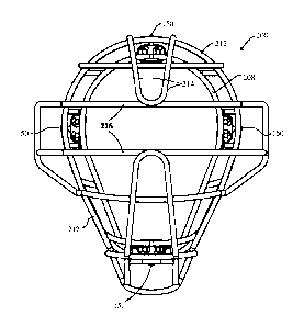
Referring to FIGS. 1-9, the first illustrative embodiment of the present
invention is
directed to a shock absorber 100 and headgear 200 that employs a shock
absorber such as, for
example, the shock absorber 100. The headgear 200 includes a faceguard 202 and
a head-
engaging member 204. The shock absorber 100 supports the protective faceguard
202 relative
to the head-engaging member 204. The shock absorber 100 includes a support
structure 102, a
guide rod 122 or 132, a sliding member 142, and a resilient member 152. The
support structure
102 is adapted for rigid attachment to either the head-engaging member 204 or
the faceguard
Date Recue/Date Received 2023-01-30
-8-
202. The guide rod 122 or 132 is supported by the support structure 102 in a
fixed position
relative to the support structure 102. The guide rod 122, 132 has first and
second end portions, a
length, and a longitudinal axis. The guide rod 122, 132 is supported by the
support structure 102
near the end portions of the guide rod. The sliding member 142 is guided by
the guide rod 122,
132 for rectilinear movement in a direction parallel to the longitudinal axis
of the guide rod.
The movement of the sliding member 142 is confined between the ends of the
guide rod 122,
132. The sliding member 142 is adapted for rigid attachment to either the head-
engaging
member 204 or the faceguard 202 depending upon which of these is the one to
which the support
structure is attached. The resilient member 152 acts on the sliding member 142
to bias the
sliding member toward one end of the guide rod 122, 132. In the illustrated
example, the
resilient member is a coil spring 154 or 156 that is provided on the guide rod
122, 132 between
the sliding member 142 and the second end portion of the guide rod and biases
the sliding
member 142 toward the first end portion of the guide rod 122, 132. In the
illustrated example,
the support structure 102 is attached to the head-engaging member 204 and the
sliding member
is attached to the faceguard 202. When an object impacts the faceguard 202,
the sliding member
142 is pushed from one end of the guide rod 122, 132 toward the other end
resulting in the
compression of the coil spring 154, 156. Thus, the resilient member 152, in
this case the coil
spring 154, 156, can absorb at least a portion of the impact energy of the
object and cushion the
blow to the faceguard 202. The movement of the sliding member 142 is limited
to a portion of
the length of the guide rod 122, 132. The movement of the sliding member 142
is limited to
rectilinear motion in a direction parallel to the longitudinal axis of the
guide rod 122, 132.
The headgear 200 of the present invention includes a head-engaging portion 204
and a
faceguard 202. The head-engaging portion 204 is made of first and second
substantially
Date Recue/Date Received 2023-01-30
-9-
enclosed frames 206 and 208, respectively. The first frame 206 is larger than
the second frame
208 and is designed to surround the wearer's face. The first frame 206 is the
closest to the
wearer's face. The second frame 208 surrounds the wearer's face and appears
roughly
concentric with the first frame 206 when viewed from the front in relation to
the wearer's face.
The second frame 208 is spaced apart from the first frame 206 such that it is
farther from the
wearer's face as compared to the first frame. The second frame 208 is
connected to the first
frame 206 by pairs of L-shaped bars 210. Each pair of L-shaped bars 210
supports a shock
absorber 100 in a protected location between the first and second frames of
the head-engaging
portion 204. The faceguard 202 includes a substantially enclosed frame 212
that surrounds the
wearer's face when viewed from the front in relation to the wearer's face. The
frame 212 of the
faceguard 202 is larger than the second frame 208 of the head-engaging portion
204 and
envelops the second frame 208 of the head-engaging portion 204 when viewed
from the front in
relation to the wearer's face. The faceguard 202 includes a first plurality of
bars 214 that are
substantially parallel to the sagittal plane of the wearer's body and a second
plurality of bars 216
that are parallel to the transverse plane of the wearer's body. These
pluralities of bars 214, 216
are attached to the frame 212 of the faceguard 202 such that they are
positioned in front of the
wearer's face and can thus provide protection to the wearer's face. The
pluralities of bars 214,
216 are positioned to provide complete protection to the entire frontal area
of the wearer's head.
The frame 212 of the faceguard 202 is attached to the plurality of shock
absorbers 100.
In the illustrated embodiment, the support structure 102 of shock absorber 100
is rigidly
attached to a corresponding pair of the L-shaped bars 210 while the sliding
member 142 is
rigidly attached to the frame 212 of the faceguard 202. The shock absorber 100
or the headgear
200 could be configured such that the sliding member 142 is attached to the
head-engaging
Date Recue/Date Received 2023-01-30
-10-
portion 204 and the support structure 102 of the shock absorber 100 is
attached to the faceguard
202. Also the attachments between the shock absorber 100 and the head-engaging
portion 204
or the attachment between the shock absorber 100 and the faceguard 202 or both
could be made
flexible instead of rigid as long as the attachment means used is resilient
and strong enough to
withstand the punishment it would be expected to receive.
The sliding member 142 has an opening 144 through it and the guide rod 122
extends
through the opening 144. The support structure 102 supports the guide rod 122
at the first end
portion 124 of the guide rod 122 and at the second end portion 126 of the
guide rod 122. The
resilient member 152 can be a coil spring 154 that has a plurality of coils.
The guide rod 122
extends through the plurality of coils of the coil spring 154. The coil spring
154 is positioned
intermediate a portion of the sliding member 142 that surrounds the opening
144 and the second
end portion 126 of the guide rod 122.
The coil spring 154 has a first end and a second end, and the first end of the
coil spring
154 bears directly or indirectly against a portion of the sliding member 142
that surrounds the
opening 144. The second end of the coil spring 154 bears directly or
indirectly against a portion
of the support structure 102 proximate the second end portion of the guide rod
122.
The sliding member 142 has at least one hole 148 for engagement by at least
one sliding
member fastener 150 to thereby rigidly attach the sliding member 142 to the
faceguard 202.
The support structure 102 has means for engagement by at least one support
structure
fastener 162, 164 to thereby rigidly attach the support structure 102 to the
head-engaging
member 204. The support structure 102 is a bracket comprising a base plate
104, a first endplate
106, and a second endplate 108. The first endplate 106 has a hole 110, 112 for
the first end
portion 124, 134 of the guide rod 122, 132. The second endplate 108 has a hole
114, 116 for the
Date Recue/Date Received 2023-01-30
-11-
second end portion 126, 136 of the guide rod 122, 132. A first lateral flange
118 is provided on
a first side of the base plate 104, and a second lateral flange 120 is
provided on a second side of
the base plate 104. The first endplate 106 is provided proximate a first end
166 of the base plate
104, and the second endplate 108 is provided proximate a second end 168 of the
base plate 104
opposite the first endplate 106. The first lateral flange 118 extends
approximately laterally from
the first side 170 of the base plate 104, and the second lateral flange 120
extends approximately
laterally from the second side 172 of the base plate 104 in a direction
approximately opposite
that of the first lateral flange 118. Each of the first lateral flange 118 and
the second lateral
flange 120 has means for engagement by at least one support structure fastener
162, 164 to
thereby rigidly attach the support structure 102 to the head-engaging member
204. Each of the
first lateral flange 118 and the second lateral flange 120 has a hole 174,
176, respectively, for
engagement by a respective support structure fastener 162, 164 to thereby
rigidly attach the
support structure 102 to the head-engaging member 204. The lateral flanges
118, 120 and the
holes 174, 176 constitute the means for engagement by at least one support
structure fastener
162, 164 to thereby rigidly attach the support structure 102 to the head-
engaging member 204.
In the illustrated embodiment, the shock absorber 100 has two guide rods 122
and 132
and two coil springs 154 and 156. The first guide rod 122 has first and second
end portions 124
and 126, a length, and a longitudinal axis. The second guide rod 132 extends
in parallel to the
first guide rod 122. The second guide rod 132 has first and second end
portions 134 and 136, a
length, and a longitudinal axis extending parallel to the longitudinal axis of
the first guide rod
122.
Accordingly, the sliding member 142 has a first opening 144 and a second
opening 146
that extend through the sliding member 142. The first guide rod 122 extends
through the first
Date Recue/Date Received 2023-01-30
-12-
opening 144 and the second guide rod 132 extends through the second opening
146. The
support structure 102 supports the first guide rod 122 at the first end
portion 124 of the first
guide rod 122 and at the second end portion 126 of the first guide rod 122.
The support
structure 102 supports the second guide rod 132 at the first end portion 134
of the second guide
rod 132 and at the second end portion 136 of the second guide rod 132.
The resilient member 152 includes the first coil spring 154 and the second
coil spring
156. The first coil spring 154 has a plurality of coils 158 and the first
guide rod 122 extends
through the plurality of coils of the first spring 154. The second coil spring
156 has a plurality
of coils 160 and the second guide rod 132 extends through the plurality of
coils of the second
spring 156. The first coil spring 154 is positioned intermediate a first
portion of the sliding
member 142 and the second end 126 of the first guide rod 122. The second coil
spring 156 is
positioned intermediate a second portion of the sliding member 142 and the
second end 136 of
the second guide rod 132.
The first coil spring 154 has a first end 155 and a second end 157. The first
end 155 of
the first coil spring 154 bears directly or indirectly against a first portion
of the sliding member
142 and the second end 157 of the first coil spring 154 bears directly or
indirectly against a first
portion of the support structure 102 proximate the second end 126 of the first
guide rod 122. In
the illustrated example, the second end 157 of the first coil spring 154 bears
directly against the
support structure 102, specifically the second endplate 108. The first end 155
of the first coil
spring 154 bears indirectly against the sliding member 142. However, the
spring 154 may bear
directly or indirectly against either of those parts while the shock absorber
remains within the
scope of the appended claims. For example, one or more washers may be provided
between the
second end 157 of spring 154 and the second endplate 108 to prevent the spring
from marring
Date Recue/Date Received 2023-01-30
-13-
the endplate, or the first end 155 of the spring 154 may directly contact the
sliding member 142
with the shock absorber still remaining functional.
The second coil spring 156 has a first end 159 and a second end 161. The first
end 159
of the second coil spring 156 bears directly or indirectly against a second
portion of the sliding
member 142 and the second end 161 of the second coil spring 156 bears directly
or indirectly
against a second portion of the support structure 102 proximate the second end
136 of the
second guide rod 132. In the illustrated example, the second end 161 of the
second coil spring
156 bears directly against the support structure 102, specifically the second
endplate 108. The
first end 159 of the second coil spring 156 bears indirectly against the
sliding member 142.
However, the spring 156 may bear directly or indirectly against either of
those parts while the
shock absorber remains within the scope of the appended claims. For example,
one or more
washers may be provided between the second end 161 of spring 156 and the
second endplate
108 to prevent the spring from marring the endplate, or the first end 159 of
the spring 156 may
directly contact the sliding member 142 with the shock absorber still
remaining functional.
In the illustrated embodiment, the first endplate 106 has a first hole 110 for
the first end
portion 124 of the first guide rod 122 and a second hole 112 for the first end
portion 134 of the
second guide rod 132. The second endplate 108 has a first hole 114 for the
second end portion
126 of the first guide rod 122 and a second hole 116 for the second end
portion 136 of the
second guide rod 132. The hole 110 is in registry with the hole 114 and the
hole 112 is in
registry with the hole 116.
The guide rod 122 has a first diameter and a second diameter. The second
diameter is
smaller than the first diameter. The second end portion 126 of the guide rod
122 is in large part
of the first diameter. The first end portion 124 and the portion of the guide
rod 122 extending
Date Recue/Date Received 2023-01-30
-14-
between the first end portion 124 and a location proximate the second end
portion 126 are
essentially of the second diameter. This arrangement forms an annular step or
shoulder 123
proximate the second end portion 126 of the first guide rod 122. The portion
of the rod 122
extending from the shoulder 123 to the second end portion 126 is of the first
diameter. The
terminal portion of the first end portion 124 of the guide rod 122 extends
through the hole 110 in
the endplate 106. An annular groove 125 is provided on the terminal portion of
the first end
portion 124 of the guide rod 122 on the side of the endplate 106 opposite the
side of the endplate
106 that faces the sliding member 142. An E-clip or retaining ring 127 is
positioned in
engagement with the groove 125. In the illustrated embodiment, the guide rod
122 is provided
with an annular flange 129 at the terminus of the second end portion 126 that
cooperates with
the clip 127 to secure the guide rod 122 to the support structure 102. The
hole 114 in endplate
108 is sized to provide clearance for the first diameter of the guide rod 122
while providing a
bearing surface for the second end portion 126 of the guide rod 122. The hole
110 has a
diameter smaller than the first diameter of the guide rod 122 and is sized to
provide clearance for
the terminal portion of the first end portion 124 of the guide rod 122 that
has the second
diameter.
The guide rod 132 has a first diameter and a second diameter. The second
diameter is
smaller than the first diameter. The second end portion 136 is in large part
of the first diameter.
The first end portion 134 and the portion of the guide rod 132 extending
between the first end
portion 134 and a location proximate the second end portion 136 are of the
second diameter.
This arrangement forms an annular step or shoulder 133 proximate the second
end portion 136.
The portion of the rod 132 extending from the shoulder 133 to the second end
portion 136 is of
the first diameter. The terminal portion of the first end portion 134 of the
guide rod 132 extends
Date Recue/Date Received 2023-01-30
-15-
through the hole 112 in the endplate 106. An annular groove 135 is provided on
the terminal
portion of the first end portion 134 of the guide rod 132 on the side of the
endplate 106 opposite
the side of the endplate 106 that faces the sliding member 142. An E-clip or
retaining ring 137
is positioned in engagement with the groove 135. In the illustrated
embodiment, the guide rod
132 is provided with an annular flange 139 at the terminus of the second end
portion 136 that
cooperates with the clip 137 to secure the guide rod 132 to the support
structure 102. The hole
116 in endplate 108 is sized to provide clearance for the first diameter of
the guide rod 132 while
providing a bearing surface for the second end portion 136 of the guide rod
132. The hole 112
has a diameter smaller than the first diameter of the guide rod 132 and is
sized to provide
clearance for the terminal portion of the first end portion 134 of the guide
rod 132 that has the
second diameter.
In the illustrated embodiment, the guide rod 122 and the guide rod 132 are
identical.
One or both of the guide rods 122 and 132 could be configured to provide a
second shoulder or
flange (not shown) near their second end portions 126, 136 such that the
second ends 157 and
161 of the springs 154 and 156 bear against that second shoulder or flange
rather than against
the second endplate 108. Thus, the second ends 157 and 161 of the springs 154
and 156 may
bear indirectly against the support structure 102.
In the illustrated embodiment, a plurality of tabs 218 are provided on the
frame 212 of
the faceguard 202. Each of the tabs 218 has a hole 220 that is engaged by a
respective fastener
150 to secure the sliding member 142 of a respective shock absorber 100 to the
faceguard 202.
The first plurality of bars 214 may also be attached to one or more of the
second plurality of bars
216. It is also possible to make the tabs 218 integral with the sliding member
142, while using a
fastener 150 to secure the sliding member 142 to the frame 212 or any of the
pluralities of bars
Date Recue/Date Received 2023-01-30
214, 216. The head-engaging member 204 is provided with padding, such as shown
in Figs.
23-27, for engagement with the wearer's head.
In the illustrated embodiment, first and second tubular sleeves 219 and 222
are provided
at the openings 144 and 146, respectively, to give a greater bearing surface
between the sliding
member 142 and the guide rods 122 and 132 so as to reduce tilting of the
sliding member
relative to the guide rods, thus reducing the possibility of the sliding
member 142 jamming on
the guide rods. The first and second tubular sleeves 219 and 222 are in
engagement with the
openings 144 and 146, respectively. The first and second tubular sleeves 219
and 222 are
identical to simplify manufacture. Each of the first and second tubular
sleeves 219 and 222 has
a first portion 224, 226, respectively, and a second portion 228, 230,
respectively. Each of the
first and second tubular sleeves 219 and 222 has an annular flange 232, 234,
respectively,
located intermediate its first portion 224, 226 and its second portion 228,
230. The guide rod
122 extends through the first sleeve 219, and the guide rod 132 extends
through the second
sleeve 222.
The first portion 224 of the first sleeve 219 fits into the opening 144 of the
sliding
member 142 with the flange 232 of the sleeve 219 abutting the sliding member
142. The second
portion 228 of the first sleeve 219 fits into the space between the coils of
the spring 154 and the
portion of the guide rod 122 that is of the second diameter. The first end 155
of the coil spring
154 engages the flange 232 of the sleeve 219 to bias the sliding member 142
toward the first end
portion 124 of the guide rod 122. Thus, the spring 154 indirectly bears
against the sliding
member 142.
The first portion 226 of the second sleeve 222 fits into the opening 146 of
the sliding
member 142 with the flange 234 of the sleeve 222 abutting the sliding member
142. The second
Date Recue/Date Received 2023-01-30
-17-
portion 230 of the second sleeve 222 fits into the space between the coils of
the spring 156 and
the portion of the guide rod 132 that is of the second diameter. The first end
159 of the coil
spring 156 engages the flange 234 of the sleeve 222 to bias the sliding member
142 toward the
first end portion 134 of the guide rod 132. Thus, the spring 156 indirectly
bears against the
sliding member 142.
The illustrated headgear is particularly suited for use by a baseball catcher
or umpire. In
use, the headgear 200 is secured to the wearer's head using straps (not shown)
or the like in the
conventional manner. Padding, such as shown in Figs. 23-27, is provided
between the
wearer's head and the head-engaging portion 204. The padding and straps must
be applied in
such a way so as to not interfere with the relative movement between the head-
engaging portion
204 and the faceguard 202. Normally, the springs 154, 156 of the shock
absorber 100 will bias
the sliding member 142 into contact with the first endplate 106. When an
object impacts the
faceguard 202, the sliding member 142 is pushed toward the endplate 108, which
causes the
springs 154, 156 to be compressed between the sliding member 142 and the
endplate 108. Thus,
the springs 154, 156 absorb at least a portion of the impact energy of the
object rather than
transmitting it to the wearer's head.
Referring to Figs. 10 and 11, a shock absorber 300 in accordance with the
second
embodiment of the present invention can be seen. The shock absorber 300 has a
support
structure 302, two guide rods 322 and 332, two coil springs 354 and 356, first
and second
tubular sleeves 419 and 422, and a sliding member 342. These parts are
essentially identical in
structure and function to the corresponding parts of the shock absorber 100,
and in turn the
shock absorber 300 is essentially identical in structure and function to the
shock absorber 100,
except as to the differences noted below. The sliding member 342 differs from
the sliding
Date Recue/Date Received 2023-01-30
-18-
member 142 in that the hole 148 is replaced by the hole 348 that extends in
the direction of the
thickness of the sliding member 342 rather than in the direction perpendicular
to the thickness of
the sliding member. The hole 348 is threaded to receive a screw fastener 350
that can secure the
strap 418 to the sliding member 342. The strap 418 has a loop that extends
between two end
portions that are each provided with a hole for the shaft of the screw 350.
The holes in the end
portions of the strap 418 are in registry with one another. The loop of the
strap 418 fits around a
portion of the frame 212 of the faceguard 202 such that, when the shaft of the
screw 350 is
placed through the holes in the end portions of the strap 418 and the screw
350 is tightened in
the hole 348, the strap 418 is clamped to the frame 212 of the faceguard 202
so as to attach the
sliding member 342 to the face guard 202.
The lateral flanges 118, 120 and the holes 174, 176 have been eliminated from
the
support structure 302. Instead, the support structure 302 is provided with a
plurality of tabs 318
that allow the support structure 302 to be welded to the bars of the head-
engaging member 204
to thereby fix the support structure 302 to the head-engaging member 204. In
addition to
welding, soldering and brazing may also be used, although welding is preferred
because it
ordinarily provides good bond strength.
The support structure 302 is a bracket comprising a base plate 304, a first
endplate 306,
and a second endplate 308. Each of the guide rods 322, 332 has a threaded hole
in the first end
portions 324, 334, respectively, for engagement by a respective one of the
screw fasteners 327,
337. The first end plate 306 has holes (not shown), corresponding to holes
110, 112 of the
support structure 102, that are smaller in diameter than the first end
portions 324, 334 of the
guide rods 322, 332 but are large enough to allow the shafts of the screw
fasteners 327, 337 to
extend through the first endplate 306. The screw fasteners 327, 337 engage the
threaded holes in
Date Recue/Date Received 2023-01-30
-19-
the first end portions 324, 334 of the guide rods 322, 332, respectively, in
order to secure the
guide rods 322, 332 to the support structure 302. The annular grooves 125, 135
and the E-clips
127, 137 are accordingly eliminated from the shock absorber 300.
The second endplate 308 has holes (not shown) corresponding to holes 114, 116
of the
support structure 102. The area around the holes in the end plate 308 is
dimpled to form dimples
315 and 317 that allow the second end portions 326, 336 of the guide rods 322,
332 to sit
substantially flush with the surface of the second endplate 308 on the side
opposite the springs
354, 356. The guide rods 322, 332 may be press fit to the holes in the dimples
315, 317, or the
second end portions 326, 336 of the guide rods 322, 332 may be welded, brazed,
or soldered to
the dimples.
Referring to Figs. 12-14, a shock absorber 500 in accordance with the third
embodiment of the present invention can be seen. The shock absorber 500 has a
support
structure 502, two guide rods 522 and 532, two coil springs 554 and 556, first
and second
tubular sleeves 619 and 622, and a sliding member 542. These parts are
essentially identical in
structure and function to the corresponding parts of the shock absorber 100,
and in turn the
shock absorber 500 is essentially identical in structure and function to the
shock absorber 100,
except as to the differences noted below.
The lateral flanges 118, 120 and the holes 174, 176 have been eliminated from
the
support structure 502. Instead, the support structure 502 is provided with a
plurality of tabs 518
that allow the support structure 502 to be welded to the bars of the head-
engaging member 204
to thereby fix the support structure 502 to the head-engaging member 204.
Referring to Figs. 15-25, a protective headgear 800 in accordance with the
fourth
embodiment of the present invention can be seen. In the headgear 800, the head-
engaging
Date Recue/Date Received 2023-01-30
-20-
portion 804 includes a shield 808 and a fixed frame 806. The shield 808 covers
the forehead,
the forward top portion of the skull, the sides of the head, and the chin of
the wearer. The shield
808 has a face opening 811 for the area corresponding to the mouth, nose, and
eyes of the
wearer. The fixed frame 806 is fixedly attached to the shield 808 on the
interior of the shield
808 such that the fixed frame 806 is positioned intermediate the shield 808
and the wearer's
head. The fixed frame 806 essentially surrounds the area corresponding to the
face opening 811
of the shield 808. Three shock absorber units 700 made in accordance with the
present
invention support the faceguard 802 relative to the head-engaging portion 804.
These three
shock absorber units 700 attach the face guard 802 to the fixed frame 806 and
thus to the head-
engaging portion 804. The shield 808 has openings 813 that allow the shock
absorber units 700
to be attached to the fixed frame 806. The shield 808 has vent openings 815 in
the top and
lateral areas around the forehead region. The shield 808 may be made of
fiberglass, carbon-fiber
composite, KEVLARO, molded polycarbonate, combinations thereof, and any other
material
suitable for use in the protective shell of protective headgear.
The shock absorber 700 has a support structure 702, two guide rods 722 and
732, two
coil springs 754 and 756, first and second tubular sleeves 819 and 822, and a
sliding member
742. These parts are essentially identical in structure and function to the
corresponding parts of
the shock absorber 100, and in turn the shock absorber 700 is essentially
identical in structure
and function to the shock absorber 100, except as to the differences noted
below.
The lateral flanges 118, 120 and the holes 174, 176 have been eliminated from
the
support structure 702. Instead, the support structure 702 is provided with a
slot 703 in the base
plate 704 of the support structure 702. An insert 705 is provided that has a
portion 707 that fits
into the slot 703 and that has a flange 709 that is too large to pass through
the slot 703. The
Date Recue/Date Received 2023-01-30
-21-
insert 705 also has holes 711 for engagement by the support structure
fasteners 762, 764. The
support structure 702 is fixed to the head-engaging member 804 by placing the
support structure
fasteners 762, 764, which may be screws or rivets for example, through holes
in the fixed frame
806 and then securing the support structure fasteners 762, 764 to the insert
705 to thereby
capture the support structure 702 between the insert 705 and the fixed frame
806. Thus the
shock absorber 700 is fixed to the head-engaging member 804. The guide rods
should be
supported high enough above the insert 705 so that the insert 705 and the
support structure
fasteners 762, 764 will not interfere with the travel of the sleeves 819, 822
and the sliding
member 742 or with the proper functioning of the springs 754, 756. The holes
711 in the insert
705 may also be countersunk to further aid in preventing the support structure
fasteners 762, 764
from interfering with the travel of the sliding member 742.
Alternatively, the support structure 702 may be provided with a plurality of
holes in the
base plate 704 of the support structure 702 that allow the support structure
702 to be fixed to the
head-engaging member 804 using the support structure fasteners 762, 764, which
may be screws
or rivets for example. The holes in the base plate 704 of the support
structure 702 for the
support structure fasteners 762, 764 would preferably be countersunk or
provided in a dimpled
region of the base plate 704 of the support structure 702 so that the support
structure fasteners
762, 764 do not interfere with the travel of the sleeves 819, 822 and the
sliding member 742 or
with the proper functioning of the springs 754, 756.
The fixed frame 806 is provided with spaced-apart bar portions 810 at
locations
corresponding to the shock absorbers 700. The support structure fasteners 762,
764 engage with
a respective spaced-apart bar portion 810 to fix the support structure 702 to
the fixed frame 806.
Date Recue/Date Received 2023-01-30
-22-
In the illustrated embodiment, a plurality of tabs 818 is provided on the
frame 812 of the
faceguard 802. Each of the tabs 818 has a hole that is engaged by a respective
fastener 750 to
secure the sliding member 742 of a respective shock absorber 700 to the
faceguard 802. The
head-engaging member 804 is preferably provided with padding, for example of a
type similar
to that illustrated in Figs. 26-31, for engagement with the wearer's head. In
the illustrated
embodiment, the faceguard 802 is of the cage type and is similar to the
faceguard 202. The
protective headgear 800 is particularly well suited for use by a hockey
goaltender.
Referring to Figs. 26-31, examples of pads for use with the protective
headgear of the
present invention or other protective headgear can be seen. The pads include
an upper pad 900
for engagement with the wearer's forehead and a lower pad 902 for engagement
with the
wearer's mandible at about the region of the chin or just above the chin. The
pads 900 and 902
may be provided with cutouts 904 and 906, visible from the front of the pad,
or they may be
otherwise dimensioned and configured to clear the shock absorbers. The lower
pad 908 uses a
downward extending bill 910 to shield the wearer's chin from the lowermost
shock absorber. A
similar configuration is used for the upper pad 914, which has an upward
extending bill 916 to
shield the wearer's forehead from the uppermost shock absorber. The upper pad
914 is
preferably also provided with an opening 918 for the straps (not shown) that
are used to secure
the headgear 200 to the wearer's head. The pads 900, 902, 908, and 914 are
preferably provided
with straps 912 that are equipped with hook-and-loop fastening systems for
attaching the pads to
the frames 206, 208, the shield 808 and the fixed frame 806. The pads
preferably have a natural
or simulated leather outer covering and a foam type cushioning material as the
filling. The foam
type cushioning material is preferably of a relatively firm variety.
Date Recue/Date Received 2023-01-30
-23-
Spring rates in the range of about 15 to about 50 lbs. seem to provide the
best results.
Most preferably, the spring rate is about 25 lbs. Any of the various disclosed
shock absorbers
and the various disclosed pads may be used with any of the disclosed
protective headgear of the
present invention or with other protective headgear.
TEST RESULTS
Testing methodology for assessing the risk of head injury associated with
athletic
headgear is promulgated by the National Operating Committee on Standards for
Athletic
Equipment (NOCSAE). There are only four independent facilities in the United
States approved
by the NOCSAE for performing testing of athletic equipment. A baseball
catcher's mask in
accordance with the present invention was tested at a NOCSAE-approved
facility. In addition,
currently-available competitive catcher's masks were also tested for
comparison. The results of
the testing are presented in Tables 1 and 2 below.
TABLE 1
Baseball Impacts
Required Velocity: 100 mph (43.81-45.60 m/s)
Peak Acceleration
Sample Impact Location Velocity (m/s) Severity
Index (g)
Front 43.86 149 123
Rawlings
Front 44.37 169 135
Front 44.24 90 54
Wilson
Front 43.86 112 127
Front 44.07 85 98
Champion
Front 43.86 119 121
Mask according Front 44.20 43 76
to the present
Front 43.86 59 74
invention
Date Recue/Date Received 2023-01-30
-24-
TABLE 2
Softball Impacts
Required Velocity: 70 mph (30.35-32.23 m/s)
Peak Acceleration
Sample Impact Location Velocity (m/s) Severity
Index (g)
Rawlings Front 30.71 96 111
Wilson Front 30.77 44 72
Champion Front 30.71 79 93
Mask according
to the present Front 30.82 11 49
invention
The Severity Index (SI) is defined as follows:
Si= A2.5 sit
=
Where: A is the instantaneous resultant acceleration expressed as a multiple
of g
(acceleration of gravity); dt are the time increments in seconds; and the
integration is carried out
over the essential duration (T) of the acceleration pulse. The lower the SI,
the lower the risk of
injury will be, while the higher acceleration is correlated with a higher risk
of injury. For a
comparable SI, the higher acceleration would present a higher risk of injury.
As can be seen from these results, the mask according to the present invention
provides
significant reductions in both SI and peak acceleration and would therefore be
expected to
correspondingly reduce the risk of injury from ball impacts.
Date Recue/Date Received 2023-01-30
-25-
It is to be understood that the present invention is not limited to the
embodiments
described above, but encompasses any and all embodiments within the scope of
the following
claims.
Date Recue/Date Received 2023-01-30