Note : Les descriptions sont présentées dans la langue officielle dans laquelle elles ont été soumises.
WO 2022/033721
PCT/EP2021/025303
1
DESCRIPTION
System comprising a cooling device for a machine enclosed in a
pressurized casing
FIELD OF THE INVENTION
Embodiments of the invention relate generally to a machine
enclosed in a pressurized casing.
In particular, embodiments of the invention relate to a cooling
device for a machine enclosed in a pressurized casing, and more
particularly to removable sealing elements of a cooling device for
circulation of a coolant medium through the pressurized casing.
Notably, integrated motor-compressor units are known, wherein
both the electric motor and the compressor are hermetically enclosed in
a cylindrical casing.
Integration of a cooling device in such a configuration requires
safety precautions related to differential pressure between the cooling
medium, water for example, and the pressurized gas inside the casing.
Notably, the pressurized gas tends to move towards the lower-pressure
cooling medium, the mixture exposing the cooling system to a potential
risk of over-pressure.
DESCRIPTION OF RELATED ART
A usual integration consists in welding the cooling device to the
inside of the pressurized casing.
Nevertheless, manufacturing is complicated and, considering the
location of the welds, it raises issues of accessibility. Besides, welding
is difficult on cast iron casing.
According to another commonly used solution, 0-rings are
positioned between a cooling jacket and the casing. Although it is
simple, this approach requires a frequent and complicated maintenance
for replacing the joints which involves entirely disassembling the
system Moreover, a potential damage of the O'ring during the assembly
would be identified only after full assembly which involves again
entirely disassembling the system.
CA 03188857 2023- 2-8
WO 2022/033721
PCT/EP2021/025303
2
There is a need to avoid at least some of the previously
mentioned drawbacks, especially by preventing a mixture between the
coolant medium circuit and the pressurized gas inside the casing.
SUMMARY
According to one aspect, a system comprising a pressurized
casing delimiting an enclosure for at least one machine and a cooling
device is proposed
The cooling device includes
a cooling jacket located inside the pressurized casing,
at least one removable sealing element between the cooling
jacket and one of a cooling medium inlet or outlet pipe located outside
the pressurized casing,
wherein the removable sealing element comprises inner and outer
cylindrical pieces extending coaxially through the casing and a flange
attached to the casing for maintaining the cylindrical pieces,
the inner cylindrical piece allowing the cooling medium
circulation between the cooling jacket and one of the cooling medium
inlet or outlet pipe,
the removable sealing element comprising a cooling medium
sealing barrier including a sealing device located between the inner
cylindrical piece and the cooling jacket, and a gas sealing barrier
including a sealing device located between the outer cylindrical piece
and the cooling jacket.
Preferably, the inner and outer cylindrical pieces are kept apart
from each other so as to form a gap connected to a vent leading to the
outside of the pressurized casing.
Advantageously, the removable sealing element may comprise an
adaptation piece, located between the casing and the flange, and
maintaining the inner and outer cylindrical pieces
Advantageously, the vent may be located in the adaptation piece.
Preferably, the gas sealing barrier further includes a sealing
device located between the outer cylindrical piece and the casing
CA 03188857 2023- 2-8
WO 2022/033721
PCT/EP2021/025303
3
Preferably, the gas sealing barrier further includes a sealing
device located between the inner cylindrical piece and the adaptation
piece, or located between the inner cylindrical piece and the flange if
the removable sealing element does not include an adaptation piece. Or
located between the inner cylindrical piece and the casing.
Advantageously, the cooling device comprises:
a first removable sealing element for the cooling medium circulation
between the cooling jacket and a cooling medium inlet pipe located
outside the pressurized casing, and
a second removable sealing element for the cooling medium
circulation between the cooling jacket and a cooling medium outlet pipe
located outside the pressurized casing.
According to one embodiment, the cooling jacket and the inner
cylindrical piece are attached by complementary screw-threads so as to
form a cooling medium sealing barrier between the inner cylindrical
piece and the cooling jacket.
Advantageously, the cooling jacket may comprise two
independent upper and lower parts, enclosing a cooling circuit and
welded one another to their extremities.
According to an alternative embodiment, the cooling jacket can
be made by additive manufacturing.
According to another alternative embodiment, the cooling jacket
can be made by casting process.
Besides, the pressurized casing may enclose at least one of the
following machines. a turbine, an electric generator, a compressor and
an electric driver.
BRIEF DESCRIPTION OF THE DRAWINGS
Other advantages and features of the invention will appear on
examination of the detailed description of embodiments, in no way
restrictive, and the appended drawings in which:
[Fig 11 represents an embodiment of a system comprising a
cooling device for a machine enclosed in a pressurized casing according
to the invention;
CA 03188857 2023- 2-8
WO 2022/033721
PCT/EP2021/025303
4
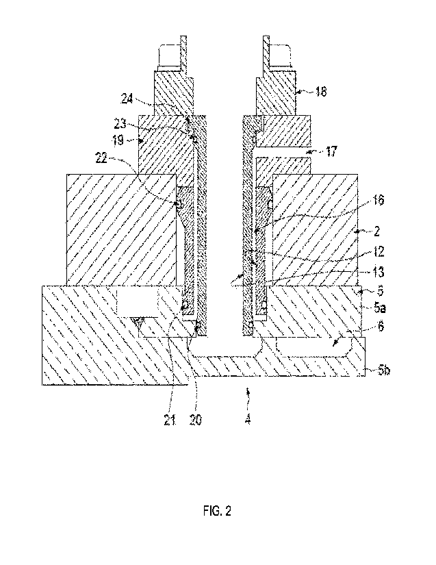
[Fig 2] is a detailed view of a removable sealing element
according to an embodiment of the invention, comprising an adaptation
piece;
[Fig 3] is a detailed view of a removable sealing element
according to another embodiment of the invention;
[Fig 4] is a detailed view of a removable sealing element
according to another embodiment of the invention, including a screw-
thread sealing; and
[Fig 5] represents another embodiment of a system comprising a
cooling device for a machine enclosed in a pressurized casing according
to the invention, comprising a passage for power supply cables.
DETAILED DESCRIPTION
Embodiments herein discloses arrangements of a compressor
cooling system comprising at least one removable sealing element for
cooling medium circulation in a cooling device extending between the
interior and the exterior of a pressurized casing.
The removable sealing element comprises at least one cooling
medium sealing barrier and one gas sealing barrier preventing the
mixture between the cooling medium flowing in the cooling circuit and
the gas contained on the pressurized casing.
Reference is made to figure 1 which represents an embodiment
of a system 1 comprising a pressurized casing 2 delimiting an enclosure
for at least one machine 3 and a cooling device 4.
In the illustrated example, the machine 3 is a motor compressor
unit. However, the pressurized casing encloses at least one of the
following machines a turbine, an electric generator, a compressor and
an electric driver
The pressurized casing 2 extends about a central axis A which is
coincident with an axis of rotation of the motor compressor unit.
The cooling device 4 includes a cooling jacket 5 located inside
the pressurized casing 2, preferably against the inner surface of the
pressurized casing 2.
CA 03188857 2023- 2-8
WO 2022/033721
PCT/EP2021/025303
As an example, the illustrated cooling jacket 5 comprises two
independent upper and lower parts, respectively 5a and 5b, enclosing a
cooling circuit 6. The upper and lower parts 5a and 5b are welded one
another to their extremities by welds 7 and 8.
5
According to alternative embodiments, the cooling jacket 5 can
be made by additive manufacturing or can be made by casting process.
The cooling circuit 6 may extend as a coil within the cooling
jacket 5.
Besides, in the illustrated example, the cooling medium is water.
The cooling device 4 further comprises at least one removable
sealing element between the cooling jacket 5 and one of a cooling
medium inlet or outlet pipe located outside the pressurized casing 2
Preferably, the cooling device 4 includes two removable sealing
elements, a first removable sealing element 9a for the cooling medium
circulation between the cooling jacket 5 and a cooling medium inlet pipe
10 and a second removable sealing element 9b for the cooling medium
circulation between the cooling jacket 5 and a cooling medium outlet
pipe 11.
The cooling medium coming from the cooling medium inlet 10
may thus penetrate the pressurized casing 2 passing through the first
removable sealing element 9a, may circulate inside the cooling jacket 5
and then get out the pressurized casing 2 passing through the second
removable sealing element 9b towards the cooling medium outlet 11.
Each removable sealing element comprises inner and outer
cylindrical pieces, respectively 12 and 13, extending coaxially through
the pressurized casing 2, in an opening provided for this purpose,
respectively 14 and 15 for the removable sealing elements 9a and 9b.
In another embodiment, inner and outer cylindrical pieces 12 and
13 can also be merged in a single element. In this case, a vent hole
between the seals is drilled.
The inner cylindrical piece 12 allows the cooling medium
circulation between the cooling jacket 5 and one of the cooling medium
inlet or outlet pipe 10, 11
CA 03188857 2023- 2-8
WO 2022/033721
PCT/EP2021/025303
6
Advantageously, for safety precaution, the inner and outer
cylindrical pieces 12, 13 are kept apart from each other so as to form a
gap 16 connected to a vent 17, visible in Figure 2, leading to the outside
of the pressurized casing 2. In case of leaks through this vent 17, one
may quickly identify if a sealing element does not operate properly.
A flange 18 is attached to the pressurized casing 2 for
maintaining the cylindrical pieces 12 and 13 For example, the flange
18 may be attached by screws. An opening is provided through the
flange 18 for the circulation of the cooling medium between the
removable sealing element 9a, 9b and the cooling medium inlet or outlet
pipe 10, 11
The embodiment of removable sealing element illustrated in
Figures 1 and 2 comprises an adaptation piece 19. The adaptation piece
19 is an intermediate piece located between the pressurized casing 2 and
the flange 18, and maintaining the inner and outer cylindrical pieces 12,
13 in position within the pressurized casing 2. As an example, the flange
18 may be attached to the pressurized casing 2 by screws passing
through the adaptation piece 19.
As illustrated, the vent 17 may be located in the adaptation piece
19.
According to an alternative embodiment shown in Figure 3, the
flange 18 may be configured to replace the adaptation piece 19. In this
case, the flange 18 may comprise the vent 17. As shown in Figure 3, the
upper part diameter of the inner cylindrical piece 12 can be
advantageously adapted to cooperate with the flange 18
Besides, each removable sealing element 9a, 9b comprises a
cooling medium sealing barrier including a sealing device 20 located
between the inner cylindrical piece 12 and the cooling jacket 5,
preventing the leaking of the cooling medium from the cooling circuit 6
to the outside of the inner cylindrical piece 12.
Each removable sealing element 9a, 9b further comprises a gas
sealing barrier including a sealing device 21 located between the outer
cylindrical piece 13 and the cooling jacket 5, preventing the leaking of
CA 03188857 2023- 2-8
WO 2022/033721
PCT/EP2021/025303
7
the gas from the pressurized casing 2 to the inside of the outer
cylindrical piece 13.
In the examples illustrated in the figures, the sealing devices of
the cooling medium sealing barrier and the gas sealing barrier include a
gasket, preferably 0-ring.
This forms a double sealing barrier preventing both cooling
medium and gas to mix
The gas sealing barrier further includes a sealing device 22,
preferably located between the outer cylindrical piece 13 and the
pressurized casing 2
The cooling medium sealing barrier of each removable sealing
element 9a, 9b of the illustrated embodiment also includes a sealing
device 23 located between the inner cylindrical piece 12 and the
adaptation piece 19 as illustrated in figure 2. The sealing device 23 can
also be located between the inner cylindrical piece 12 and the flange 18
as illustrated in figure 3, or located between the inner cylindrical piece
12 and the casing 2 (not illustrated here), if the removable sealing
element 9a, 9b does not include an adaptation piece 19.
Each of the sealing devices 20 and 23 of the cooling medium
sealing barrier is located at one end of the inner cylindrical piece 12,
and each of the sealing devices 21 and 22 of the gas sealing barrier is
located at one end of the outer cylindrical piece 13.
The inner cylindrical piece 12 may include an upper rim 24
cooperating with the adaptation piece 19 or the flange 18 if no
adaptation piece 19 is provided, in order to be well positioned and well
aligned within the opening 14, 15 of the casing 2.
Referring now to Figure 4 which depicts another embodiment of
the cooling medium sealing barrier, the cooling jacket 5 and the inner
cylindrical piece 12 are attached by complementary screw-threads so as
to form the sealing device 20 of the cooling medium sealing barrier
between the inner cylindrical piece 12 and the cooling jacket 5. The
sealing device may be for example a gas thread or NPT thread ("National
Pipe Thread", NPT)
CA 03188857 2023- 2-8
WO 2022/033721
PCT/EP2021/025303
8
Furthermore, the pressurized casing 2 of the system 1 may also
be provided with an opening 25 for the passage of power supply cables
from the machine 3 to a terminal box 26, visible in Figure 5.
In this embodiment, the cooling jacket 5 is advantageously
provided with a passage 27.
In order to protect the power supply cables against the gas, an
outer cylindrical piece 13 and, for example, an adaptation piece 19, may
be inserted within the opening 25 of the pressurized casing 2
Referring now to Figures 1, 2, 3, 4 and 5, one operating cycle of
the system 1 will now be described In operation, cooling medium from
cooling medium inlet pipe 10 can penetrate the interior of the
pressurized casing 2 through the inner cylindrical piece 12 of the first
removable sealing element 9a and circulates through the cooling circuit
6 of the cooling jacket 5 for cooling of the motor compressor unit 3.
The first removable sealing element comprises a cooling medium
sealing barrier including a sealing device 20 located between the inner
cylindrical piece 12 and the cooling jacket 5. Besides, a gas sealing
barrier including a sealing device 21 is located between the outer
cylindrical piece 13, which extends coaxially of the inner cylindrical
piece 12, and the cooling jacket 5
The cooling medium sealing barrier and the gas sealing barrier
of the system prevent the risk of over-pressure by preventing the mixture
between gas and cooling medium.
In a similar way, cooling medium can then flow back to the
exterior of the pressurized casing 2, circulating through the second
removable sealing element 9b, towards the cooling medium outlet pipe
11.
The configuration of the removable sealing elements 9a, 9b an
enable a fast and easy maintenance.
CA 03188857 2023- 2-8