Note : Les descriptions sont présentées dans la langue officielle dans laquelle elles ont été soumises.
CA 03189783 2023-01-20
WO 2022/020571
PCT/US2021/042743
1
LIGHTING FIXTURE WITH PERIPHERAL LIGHT EMISSION FEATURE
Cross-Reference to Related Applications
[0001] This application claims priority to U.S. Provisional Patent
Application No.
63/055,847 filed on July 23, 2020 and to U.S. Provisional Patent Application
No.
63/055,895 filed on July 23, 2020, wherein the entire disclosures of the
foregoing
applications are hereby incorporated by reference herein.
Field of the Disclosure
[0002] The present disclosure relates to a lighting fixtures incorporating
peripheral
light emission features and/or waveguides, as well as systems incorporating
such
fixtures.
Background
[0003] Lighting fixtures increasingly utilize lighting technologies with
increased
efficiency (e.g., relative to incandescent light bulbs) and/or which produce a
more
pleasing, natural light (e.g., relative to fluorescent lighting fixtures). One
such
lighting technology is light emitting diodes (LEDs). Compared with
incandescent
sources, LED-based lighting fixtures are much more efficient at converting
electrical
energy into light, are longer lasting, and are also capable of producing light
that is
very natural. Compared with fluorescent lighting, LED-based fixtures are also
very
efficient, but are capable of producing light that is much more natural and
more
capable of accurately rendering colors. LED sources may also be provided in
numerous color points and may be controlled to provide lighting effects not
easily
achievable with other (e.g., incandescent and fluorescent) sources in light
fixtures.
As a result, lighting fixtures that employ LED technologies are replacing
incandescent and fluorescent bulbs in residential, commercial, and industrial
applications.
[0004] Various LED-based lighting fixtures are known. However, some of
these
lighting fixtures may provide inferior performance and/or aesthetics. For
example,
some ceiling-mounted lighting fixtures may direct and/or reflect light in such
a way
that results in hard and uneven illumination. Further, it may be challenging
to
integrate conventional lighting fixtures with architectural and/or functional
features
CA 03189783 2023-01-20
WO 2022/020571
PCT/US2021/042743
2
that may be provided in a space to be illuminated, particularly in a manner
that is
cost effective, aesthetically pleasing, and/or unobtrusive.
[0005] A skylight is a window that is generally installed in a roof or
ceiling.
Windows, including skylights, beneficially admit natural light and are
desirable in
residential and commercial buildings. Providing natural light is known to
enhance
mood, increase productivity, maintain circadian rhythms, and improve ambiance
among other benefits. Skylights can be used to supplement natural light
provided by
windows, and frequently represent the only option to provide natural light to
interior
spaces that do not abut exterior walls of a structure where windows would be
ineffective.
[0006] Unfortunately, providing skylights in many spaces is impractical
or
impossible. The lower floors of a multi-story building typically lack direct
access to
the roof of the building. In many instances, even a top floor of a building
may have
structural or mechanical components that prevent the installation of
skylights, limit
the functionality of skylights, or would cause installation of the skylights
to be too
expensive.
[0007] Accordingly, there is a need to provide the benefits of windows
and/or
skylights to spaces where installation of skylights and/or windows would be
impractical or impossible, particularly in a manner that is cost-effective and
aesthetically pleasing.
Summary
[0008] The present disclosure relates to a lighting fixture
incorporating a
peripheral light emission feature. A peripheral light emission feature may
include a
plurality of light sources distributed around a periphery of the lighting
fixture and
configured to illuminate a peripheral light emission feature defining a
peripheral
region, optionally in conjunction with a peripheral reflector defining a
peripheral
reflector region laterally enclosing a non-reflector region and arranged
around
substantially an entire perimeter of the lighting fixture. A peripheral light
emission
feature may include a waveguide defining a peripheral waveguide region
laterally
enclosing a non-waveguide region and arranged around substantially an entire
perimeter of the lighting fixture. A peripheral light emission feature may
include at
least one waveguide that is used in conjunction with a light-transmissive
panel, with
the waveguide and light-transmissive panel being illuminated by different
light
CA 03189783 2023-01-20
WO 2022/020571
PCT/US2021/042743
3
sources. A lighting fixture may include a light-transmissive panel that is
configured to
be recessed, at least one waveguide positioned along a perimeter of the light-
transmissive panel and transverse to the light-transmissive panel, separate
light
sources configured to illuminate the light-transmissive panel and the at least
one
waveguide, and control circuitry. The control circuitry is configured to
selectively
adjust intensity and/or color temperature of the light sources to cause
aggregate
emissions of the lighting fixture to dynamically change over time. Portions or
an
entirety of a resulting light fixture may resemble a skylight or transom
window. A
lighting system incorporates a plurality of lighting fixtures each including a
light
transmissive panel, at least one waveguide, and separate light sources
configured to
illuminate the light-transmissive panel and the at least one waveguide, and
control
circuitry. The control circuitry is configured to selectively adjust intensity
and/or color
temperature of the light sources to cause aggregate emissions of the lighting
fixture
to dynamically change over time, wherein during at least some times the
dynamic
change of emissions of the lighting system includes simultaneous operation of
different lighting fixtures to provide different intensities and/or color
temperatures.
Lighting fixtures may be suspended or recessed, and such fixtures may be
operated
in a manner that a viewer perceives at least portions of a space as being
naturally
illuminated.
[0009] In one aspect, a lighting fixture includes: a light-transmissive
panel; at
least one peripheral light emission feature arranged around at least part of a
periphery of the light-transmissive panel; at least one first light source
configured to
illuminate the light-transmissive panel; at least one second light source
configured to
illuminate the at least one peripheral light emission feature; and control
circuitry
configured to selectively adjust, for one or more of the at least one first
light source
and the at least one second light source, at least one of intensity and color
temperature to cause aggregate emissions of the lighting fixture to
dynamically
change over time.
[0010] In certain embodiments, the at least one peripheral light
emission feature
comprises at least one waveguide that comprises at least one light extraction
feature
configured to emit light into a space to be illuminated by the lighting
fixture.
[0011] In certain embodiments, the at least one waveguide comprises a
face that
is transversely oriented relative to the light-transmissive panel and extends
from the
CA 03189783 2023-01-20
WO 2022/020571
PCT/US2021/042743
4
light-transmissive panel to a waveguide distal edge that is spaced from the
light-
transmissive panel.
[0012] In certain embodiments, the at least one waveguide comprises a
plurality
of waveguides, the at least one second light source comprises a plurality of
second
light sources, and each second light source is configured to illuminate a
different
waveguide of the plurality of waveguides.
[0013] In certain embodiments, the at least one peripheral light
emission feature
comprises at least one peripheral reflector region that is configured to
reflect at least
a portion of emissions of the at least one second light source in a downward
direction.
[0014] In certain embodiments, the at least one first light source
comprises a first
plurality of LEDs, and the at least one second light source comprises a second
plurality of LEDs.
[0015] In certain embodiments, the at least one light-transmissive panel
in
combination with the first light source are configured to emulate a window
portion of
a traditional skylight, without allowing transmission of natural light from an
external
environment through the at least one light-transmissive panel.
[0016] In certain embodiments, the control circuitry is configured to
selectively
adjust at least one of intensity and color temperature for the at least one
first light
source and for the at least one second light source to illuminate the light-
transmissive panel and the at least one peripheral light emission feature such
that
the lighting fixture resembles a skylight that is externally illuminated by
the sun, and
such that a perceived direction of external illumination of the lighting
fixture moves
from east to west over time. The control circuitry may be additionally or
separately
configured to provide any other effects disclosed herein.
[0017] In another aspect, a lighting fixture includes a light-
transmissive panel
configured to be recessed with respect to a surface of a static structure, and
at least
one waveguide positioned along a perimeter of the light-transmissive panel,
wherein
the at least one waveguide comprises a face that is transversely oriented
relative to
the light-transmissive panel and extends from the light-transmissive panel to
a
waveguide distal edge that is spaced from the light-transmissive panel. The
lighting
fixture further includes at least one first light source configured to
illuminate the light-
transmissive panel, and at least one second light source configured to
illuminate the
at least one waveguide. The lighting fixture additionally includes control
circuitry that
CA 03189783 2023-01-20
WO 2022/020571
PCT/US2021/042743
is configured to selectively adjust, for one or more of the at least one first
light source
and the at least one second light source, at least one of intensity and color
temperature to cause aggregate emissions of the lighting fixture to
dynamically
change over time.
5 [0018] In certain embodiments, the control circuitry is configured
to selectively
adjust at least one of intensity and color temperature for the at least one
first light
source and for the at least one second light source to illuminate the light-
transmissive panel and the at least one waveguide such that the lighting
fixture
resembles a skylight that is externally illuminated by the sun, and such that
a
perceived direction of external illumination of the lighting fixture moves
from east to
west over time.
[0019] In certain embodiments, the control circuitry is configured to
selectively
adjust at least one of intensity and color temperature for the at least one
second light
source to illuminate the at least one waveguide in a manner such that the at
least
one waveguide resembles being externally illuminated by the sun with a
perceived
direction of external illumination of the at least one waveguide moving from
east to
west over time, while the light-transmissive panel is illuminated by the at
least one
first light source but does not appear to be externally illuminated by the
sun.
Restated, the at least one waveguide may appear to be sun-illuminated while
the
light-transmissive panel does not appear to be sun-illuminated.
[0020] In certain embodiments, the control circuitry is configured to
selectively
adjust at least one of intensity and color temperature for the at least one
first light
source to illuminate the light-transmissive panel in a manner such that the
light-
transmissive panel resembles being externally illuminated by the sun with a
perceived direction of external illumination of the light-transmissive panel
moving
from east to west over time, while the at least one waveguide is illuminated
by the at
least one second light source but does not appear to be externally illuminated
by the
sun. Restated, the light-transmissive panel may appear to be sun-illuminated
while
the at least one waveguide does not appear to be sun-illuminated.
[0021] In certain embodiments, the at least one waveguide comprises a
plurality
of waveguides, the at least one second light source comprises a plurality of
second
light sources, and each second light source is configured to illuminate a
different
waveguide of the plurality of waveguides.
CA 03189783 2023-01-20
WO 2022/020571
PCT/US2021/042743
6
[0022] In certain embodiments, the at least one waveguide comprises a
plurality
of waveguides; the at least one second light source comprises a plurality of
second
light sources, with each second light source of the plurality of second light
sources
being configured to illuminate a different waveguide of the plurality of
waveguides;
.. the light-transmissive panel comprises a substantially rectangular shape
bounded by
first through fourth edges of the light-transmissive panel; the plurality of
waveguides
comprises first through fourth waveguides bounding the first through fourth
edges of
the light-transmissive panel, respectively; and each second light source of
the
plurality of second light sources is separately controllable by the control
circuitry to
separately adjust at least one of intensity and color temperature of emissions
with
which the first through fourth waveguides are illuminated. Such an embodiment
may
be suitable for in-ceiling mounting.
[0023] In certain embodiments, the at least one waveguide comprises a
plurality
of waveguides; the at least one second light source comprises a plurality of
second
light sources, with each second light source of the plurality of second light
sources
being configured to illuminate a different waveguide of the plurality of
waveguides;
the light-transmissive panel comprises a substantially rectangular shape
bounded by
first through fourth edges of the illuminated panel; the plurality of
waveguides
comprises first through third waveguides bounding first through third edges of
the
illuminated panel, respectively; and each second light source of the plurality
of
second light sources is separately controllable by the control circuitry to
separately
adjust at least one of intensity and color temperature of emissions with which
the first
through third waveguides are illuminated. Such an embodiment may be suitable
for
mounting within a wall (e.g., to resemble a transom window).
[0024] In certain embodiments, the static structure comprises a lateral
wall of a
space to be illuminated, and the light-transmissive panel is recessed into the
lateral
wall.
[0025] In certain embodiments, the at least one waveguide comprises a
face
having a plurality of light extraction features.
In certain embodiments, the at least one waveguide comprises a plurality of
waveguides, and at least some waveguides of the plurality of waveguides are
substantially coplanar.
[0026] In certain embodiments, the at least one waveguide comprises a
curved
face.
CA 03189783 2023-01-20
WO 2022/020571
PCT/US2021/042743
7
[0027] In another aspect, the disclosure relates to a lighting system
that includes
a plurality of lighting fixtures arranged in a single space to be illuminated
and
associated control circuitry. Each lighting fixture comprises: a light-
transmissive
panel; at least one waveguide positioned along a perimeter of the light-
transmissive
panel, wherein the at least one waveguide comprises a face that is
transversely
oriented relative to the light-transmissive panel and extends from the light-
transmissive panel to a waveguide distal edge spaced from the light-
transmissive
panel; at least one first light source configured to illuminate the light-
transmissive
panel; and at least one second light source configured to illuminate the at
least one
waveguide. The control circuitry is configured to selectively adjust, for one
or more
of (i) at least one light source and (ii) the at least one second light source
and
separately for each lighting fixture of the plurality of lighting fixtures, at
least one of
intensity and color temperature to cause emissions of the lighting system to
dynamically change over time, wherein during at least some times the dynamic
change of emissions of the lighting system includes simultaneous illumination
of
different lighting fixtures of the plurality of lighting fixtures at different
intensities
and/or color temperatures.
[0028] In certain embodiments, at least a portion of each lighting
fixture of the
plurality of lighting fixtures resembles a skylight that is externally
illuminated by the
sun, and the dynamic change of emissions of the lighting system includes
illumination of different lighting fixtures of the plurality of lighting
fixtures at different
intensities and/or color temperatures to cause a perceived direction of
external
illumination of the plurality of lighting fixtures to move from east to west
over time.
[0029] In certain embodiments, for each lighting fixture of the
plurality of lighting
fixtures, the at least one waveguide comprises a plurality of waveguides, the
at least
one second light source comprises a plurality of second light sources, and
each
second light source is configured to illuminate a different waveguide of the
plurality of
waveguides.
[0030] In certain embodiments, at least one lighting fixture of the
plurality of
lighting fixtures is configured to be recessed into a static structure
bounding at least
a portion of a space to be illuminated.
[0031] In certain embodiments, at least one lighting fixture of the
plurality of
lighting fixtures is configured to be suspended from a ceiling structure. In
certain
CA 03189783 2023-01-20
WO 2022/020571
PCT/US2021/042743
8
embodiments, the at least one lighting fixture further comprises a third light
source
configured to transmit emissions in an upward direction.
[0032] In certain embodiments, the control circuitry is further
configured to
selectively adjust, for the third light source of the at least one lighting
fixture, at least
one of intensity and color temperature of to cause emissions of the third
light source
to dynamically change over time.
[0033] In another aspect, a lighting fixture includes at least one
peripheral
reflector defining at least one peripheral reflector region laterally
enclosing a non-
reflector region, wherein the at least one peripheral reflector region is
arranged
around substantially an entire perimeter of the lighting fixture. The lighting
fixture
further includes a plurality of light sources distributed around a periphery
of the
lighting fixture and configured to illuminate the at least one peripheral
reflector
region. The at least one peripheral reflector is configured to reflect at
least a portion
of emissions of the plurality of light sources in a downward direction.
[0034] In certain embodiments, the at least one peripheral reflector is
configured
to reflect substantially an entirety of the emissions of the plurality of
light sources in
the downward direction for indirect illumination of a space in which the
lighting fixture
is arranged. In certain embodiments, the at least one peripheral reflector
includes a
curved cross-sectional shape. In certain embodiments, the at least one
peripheral
reflector is configured for diffuse reflection. In certain embodiments, the at
least one
peripheral reflector is configured for specular reflection. In certain
embodiments, the
at least one peripheral reflector region is arranged around at least 95% of
the entire
perimeter. In certain embodiments, the at least one peripheral reflector
region is
arranged around the entire perimeter. In certain embodiments, the at least one
peripheral reflector region includes less than 50% of a total projected bottom
area of
the lighting fixture. In certain embodiments, the at least one peripheral
reflector
region includes less than 20% of a total projected bottom area of the lighting
fixture.
[0035] In certain embodiments, the at least one reflector region
encloses a shape
that is generally rectangular, hexagonal, circular, or oval. In certain
embodiments,
the at least one reflector region encloses a shape having four or more sides.
In
certain embodiments, the non-reflector region includes an unfilled opening. In
certain embodiments, the non-reflector region includes an opening arranged in
the
non-reflector region, the opening configured to be at least partially filled
by at least
one functional feature. In certain embodiments, the at least one functional
feature
CA 03189783 2023-01-20
WO 2022/020571
PCT/US2021/042743
9
includes at least one of a ceiling tile, an air duct opening, a downlight, a
skylight, a
light-transmissive panel resembling a skylight (i.e., a skylight fixture), a
smoke
detector, or a sensor. In certain embodiments, the lighting fixture further
includes
acoustic insulation arranged within at least a portion of the non-reflector
region.
[0036] In certain embodiments, the lighting fixture is devoid of a lens
arranged
between the plurality of light sources and a light output surface configured
to direct
the at least a portion of the emissions of the plurality of light sources in
the
downward direction. In certain embodiments, the lighting fixture is devoid of
a
diffuser arranged between the plurality of light sources and a light output
surface
configured to direct the at least a portion of the emissions of the plurality
of light
sources in the downward direction. In certain embodiments, the lighting
fixture is
devoid of a lens and a diffuser in a light path originating from the plurality
of light
sources and the at least a portion of the emissions emitted into an
environment
containing the lighting fixture.
[0037] In certain embodiments, the lighting fixture is configured to be at
least
partially recessed into a ceiling structure, flush mounted to a ceiling
structure, or
suspended from a ceiling structure. In certain embodiments, the lighting
fixture is
configured to be at least partially recessed into a ceiling structure.
Further, light
sources of a plurality of light sources are configured to be positioned below
a visible
ceiling plane of the ceiling structure. In certain embodiments, light sources
of the
plurality of light sources are distributed around an inner edge of the at
least one
peripheral reflector region. In certain embodiments, light sources of the
plurality of
light sources are inset relative to an outer edge of the at least one
peripheral
reflector region.
[0038] In certain embodiments, a lighting system includes a plurality of
the
lighting fixtures arranged to illuminate a space. In certain embodiments, each
lighting fixture of the plurality of lighting fixtures abuts at least one
other lighting
fixture of the plurality of lighting fixtures in an array. In certain
embodiments, the
array is a one-dimensional array. In certain embodiments, the array is a two-
dimensional array. In certain embodiments, the lighting system further
includes
control circuitry configured to separately adjust, for each lighting fixture
of the
plurality of lighting fixtures, at least one of intensity, color temperature,
and
directionality of emissions of the lighting fixture to cause aggregate
emissions of the
lighting system to dynamically change over time. In certain embodiments, the
CA 03189783 2023-01-20
WO 2022/020571
PCT/US2021/042743
control circuitry is configured to selectively illuminate a plurality of solid-
state light
sources such that a perceived direction of external illumination of the
lighting fixture
moves from east to west over time.
[0039] In another aspect, a lighting fixture includes a plurality of
subassemblies
5 arranged in an array. Each subassembly of the plurality of subassemblies
includes
at least one peripheral reflector defining at least one peripheral reflector
region
laterally enclosing a non-reflector region, wherein the at least one
peripheral reflector
region is arranged around substantially an entire perimeter of the non-
reflector
region. Each subassembly further includes a plurality of light sources
distributed
10 around a periphery of the non-reflector region and configured to
illuminate the at
least one peripheral reflector region. The at least one peripheral reflector
is
configured to reflect at least a portion of emissions of the plurality of
light sources in
a downward direction.
[0040] In certain embodiments, for at least one subassembly of the
plurality of
subassemblies, the at least one peripheral reflector is configured to reflect
substantially an entirety of the emissions of the plurality of light sources
in the
downward direction for indirect illumination of a space in which the lighting
fixture is
arranged. In certain embodiments, for at least one subassembly of the
plurality of
subassemblies, the at least one peripheral reflector includes a curved cross-
sectional shape. In certain embodiments, for at least one subassembly of the
plurality of subassemblies, the at least one peripheral reflector is
configured for
diffuse reflection. In certain embodiments, for at least one subassembly of
the
plurality of subassemblies, the at least one peripheral reflector is
configured for
specular reflection. In certain embodiments, for at least one subassembly of
the
plurality of subassemblies, the at least one peripheral reflector region is
arranged
around at least 95% of the entire perimeter of the non-reflector region of the
subassembly. In certain embodiments, for at least one subassembly of the
plurality
of subassemblies, the at least one peripheral reflector region is arranged
around the
entire perimeter of the non-reflector region of the subassembly. In certain
embodiments, for at least one subassembly of the plurality of subassemblies,
the at
least one peripheral reflector region includes less than 50% of a total
projected
bottom area of the subassembly. In certain embodiments, for at least one
subassembly of the plurality of subassemblies, the at least one peripheral
reflector
region includes less than 20% of a total projected bottom area of the
subassembly.
CA 03189783 2023-01-20
WO 2022/020571
PCT/US2021/042743
11
[0041] In certain embodiments, for at least one subassembly of the
plurality of
subassemblies, the at least one reflector region encloses a shape that is
generally
rectangular, hexagonal, circular, or oval. In certain embodiments, for at
least one
subassembly of the plurality of subassemblies, the at least one reflector
region
encloses a shape having four or more sides. In certain embodiments, for at
least
one subassembly of the plurality of subassemblies, the non-reflector region
includes
an unfilled opening. In certain embodiments, for at least one subassembly of
the
plurality of subassemblies, the non-reflector region includes an opening
arranged in
the non-reflector region, the opening configured to be at least partially
filled by at
least one functional feature. In certain embodiments, the at least one
functional
feature includes at least one of a ceiling tile, an air duct opening, a
downlight, a
skylight, a light-transmissive panel resembling a skylight (i.e., a skylight
fixture), a
smoke detector, or a sensor. In certain embodiments, at least one subassembly
of
the plurality of subassemblies further includes acoustic insulation arranged
within at
least a portion of the non-reflector region.
[0042] In certain embodiments, at least one subassembly of the plurality
of
subassemblies is devoid of a lens arranged between the plurality of light
sources and
a light output surface configured to direct the at least a portion of the
emissions of
the plurality of light sources in the downward direction. In certain
embodiments, at
least one subassembly of the plurality of subassemblies is devoid of a
diffuser
arranged between the plurality of light sources and a light output surface
configured
to direct the at least a portion of the emissions of the plurality of light
sources in the
downward direction. In certain embodiments, at least one subassembly of the
plurality of subassemblies is devoid of a lens and a diffuser in a light path
originating
from the plurality of light sources and the at least a portion of the
emissions emitted
into an environment containing the lighting fixture.
[0043] In certain embodiments, the lighting fixture is configured to be
at least
partially recessed into a ceiling structure, flush mounted to a ceiling
structure, or
suspended from a ceiling structure. In certain embodiments, the lighting
fixture is
configured to be at least partially recessed into a ceiling structure.
Further, for at
least one subassembly of the plurality of subassemblies, light sources are
configured
to be positioned below a visible ceiling plane of the ceiling structure. In
certain
embodiments, for at least one subassembly of the plurality of subassemblies,
light
sources are distributed around an inner edge of the at least one peripheral
reflector
CA 03189783 2023-01-20
WO 2022/020571
PCT/US2021/042743
12
region. In certain embodiments, for at least one subassembly of the plurality
of
subassemblies, light sources are inset relative to an outer edge of the at
least one
peripheral reflector region.
[0044] In certain embodiments, the array is a one-dimensional array. In
certain
embodiments, the array is a two-dimensional array. In certain embodiments, for
at
least one subassembly of the plurality of subassemblies, at least a portion of
the at
least one peripheral reflector region overlaps with at least a portion of a
peripheral
reflector region of another subassembly of the plurality of subassemblies.
[0045] In another aspect, a lighting fixture includes at least one
peripheral
waveguide defining at least one peripheral waveguide region laterally
enclosing a
non-waveguide region, wherein the at least one peripheral waveguide region is
arranged around substantially an entire perimeter of the lighting fixture. The
lighting
fixture further includes a plurality of light sources configured to illuminate
the at least
one peripheral waveguide region.
[0046] In certain embodiments, the at least one peripheral waveguide region
is
arranged around at least 95% of the entire perimeter of the lighting fixture.
In certain
embodiments, the at least one peripheral waveguide region is arranged around
the
entire perimeter of the lighting fixture. In certain embodiments, the at least
one
peripheral waveguide region includes less than 50% of a total projected bottom
area
of the lighting fixture. In certain embodiments, the at least one peripheral
waveguide
region includes less than 20% of a total projected bottom area of the lighting
fixture.
[0047] In certain embodiments, the at least one waveguide region
encloses a
shape that is generally rectangular, hexagonal, circular, or oval. In certain
embodiments, the at least one waveguide region encloses a shape having four or
more sides. In certain embodiments, the non-waveguide region includes an
unfilled
opening. In certain embodiments, the non-waveguide region includes an opening
arranged in the non-waveguide region, and the opening is configured to be at
least
partially filled by at least one functional feature. In certain embodiments,
the at least
one functional feature includes at least one of a ceiling tile, an air duct
opening, a
downlight, a skylight, a light-transmissive panel resembling a skylight (i.e.,
a skylight
fixture), a smoke detector, or a sensor. In certain embodiments, the lighting
fixture
further includes acoustic insulation arranged within at least a portion of the
non-
waveguide region.
CA 03189783 2023-01-20
WO 2022/020571
PCT/US2021/042743
13
[0048] In certain embodiments, the lighting fixture is configured to be
at least
partially recessed into a ceiling structure, flush mounted to a ceiling
structure, or
suspended from a ceiling structure. In certain embodiments, light sources of
the
plurality of light sources are distributed around an inner edge of the at
least one
peripheral waveguide region. In certain embodiments, light sources of the
plurality of
light sources are inset relative to an outer edge of the at least one
peripheral
waveguide region.
[0049] In certain embodiments, a lighting system includes a plurality of
lighting
fixtures arranged to illuminate a space. In certain embodiments, lighting
fixtures of
the plurality of lighting fixtures are arranged in a one-dimensional array. In
certain
embodiments, lighting fixtures of the plurality of lighting fixtures are
arranged in a
two-dimensional array.
[0050] In another aspect, any of the foregoing aspects, and/or various
separate
aspects and features as described herein, may be combined for additional
advantage. Any of the various features and elements as disclosed herein may be
combined with one or more other disclosed features and elements unless
indicated
to the contrary herein.
[0051] Those skilled in the art will appreciate the scope of the present
disclosure
and realize additional aspects thereof after reading the following detailed
description
of the preferred embodiments in association with the accompanying drawing
figures.
Brief Description of the Drawings
[0052] The accompanying drawing figures incorporated in and forming a
part of
this specification illustrate several aspects of the disclosure, and together
with the
description serve to explain the principles of the disclosure.
[0053] FIG. 1 is a cross-sectional view of a lighting fixture according
to one
embodiment of the present disclosure, including an illuminated light-
transmissive
panel configured to emit light in a downward direction, two illuminated
waveguides
arranged in parallel along peripheral portions of and extending in a
transverse
direction relative to the light-transmissive panel, and an illuminated upper
portion
configured to emit light in an upward direction.
[0054] FIG. 2 is a perspective view of the lighting fixture of FIG. 1.
[0055] FIG. 3 is a schematic perspective view of a lighting fixture
according to
one embodiment including an illuminated light-transmissive panel bounded along
CA 03189783 2023-01-20
WO 2022/020571
PCT/US2021/042743
14
four sides by illuminated waveguides that extend in a transverse direction
relative to
the light-transmissive panel.
[0056] FIG. 4A is a perspective view of a portion of a lighting fixture
useable as a
transom window, including an illuminated light-transmissive panel bounded
along
three sides by illuminated waveguides that extend in a transverse direction
relative to
the light-transmissive panel, and bounded along a fourth side by a reflective
(e.g.,
upper) surface.
[0057] FIG. 4B is a perspective view of a lighting fixture incorporating
the portion
shown in FIG. 4A.
[0058] FIG. 5 is a cross-sectional view of a lighting fixture similar to
that shown in
FIGS. 4A-4B, but with waveguide and/or reflector surfaces angled non-
perpendicular
to a light-transmissive panel.
[0059] FIG. 6 is a perspective view of three lighting fixtures according
to FIG. 5
recessed within a wall and oriented in a horizontal direction to resemble
transom
windows at a level generally above a door defined in the wall.
[0060] FIG. 7 is a perspective view of a lighting fixture recessed
within a wall,
extending from floor to ceiling, and oriented in a vertical direction to
resemble a
window, with the lighting fixture including an illuminated light-transmissive
panel
bounded along four sides by illuminated waveguides that extend in a transverse
direction relative to the light-transmissive panel.
[0061] FIG. 8 is a perspective view of a lighting fixture recessed
within a ceiling
and extending horizontally to a wall-ceiling interface, with the lighting
fixture including
an illuminated light-transmissive panel bounded along four sides by
illuminated
waveguides that extend in a transverse direction relative to the light-
transmissive
panel.
[0062] FIG. 9A is a perspective view of two lighting fixtures installed
in a wall and
a ceiling, respectively, with the lighting fixtures abutting one another at a
wall-ceiling
interface, and with each lighting fixture including an illuminated light-
transmissive
panel bounded along four sides by illuminated waveguides that extend in a
transverse direction relative to the light-transmissive panel.
[0063] FIGS. 9B and 9C are magnified perspective views of portions of
the two
lighting fixtures of FIG. 9A proximate to the wall-ceiling interface.
[0064] FIG. 10 is a schematic illustrating components of an intelligent
lighting
network according to one embodiment of the present disclosure.
CA 03189783 2023-01-20
WO 2022/020571
PCT/US2021/042743
[0065] FIG. 11 is a high-level schematic illustrating control components
of a
lighting fixture in the intelligent lighting network of FIG. 10.
[0066] FIG. 12 is a schematic illustrating interconnections between
components
of a driver module and an LED array according to one embodiment of the present
5 disclosure.
[0067] FIG. 13A is a diagram illustrating a first dynamic lighting
operating state
provided by a lighting system incorporating multiple light fixtures as
disclosed herein.
[0068] FIG. 13B is a diagram illustrating a second dynamic lighting
operating
state provided by the lighting system of FIG. 13A.
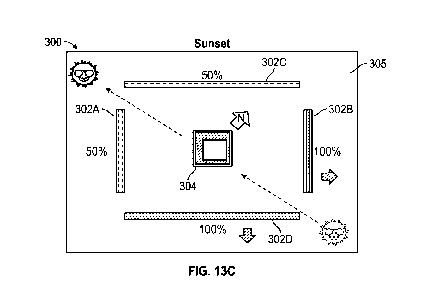
10 [0069] FIG. 13C is a diagram illustrating a third dynamic lighting
operating state
provided by the lighting system of FIG. 13A.
[0070] FIG. 14 is a perspective view of a lighting fixture according to
one
embodiment including an illuminated light-transmissive panel configured to
emit light
in a downward direction, and two groups of illuminated waveguides having a
15 substantially planar light emitting faces and arranged in parallel along
peripheral
portions of, and extending in a transverse direction relative to, the light-
transmissive
panel.
[0071] FIG. 15 is a perspective view of a lighting fixture according to
one
embodiment including an illuminated light-transmissive panel of an annular
shape
configured to emit light in a downward direction, and two circular groups of
illuminated waveguides each having curved light-emitting faces and extending
in a
transverse direction relative to the light-transmissive panel.
[0072] FIG. 16 is a perspective view of a lighting fixture according to
one
embodiment including four illuminated light-transmissive panels arranged in a
rectangular assembly and configured to emit light in a downward direction,
with each
light-transmissive panel being bordered by two parallel groups of illuminated
waveguides each having a generally planar light-emitting face and extending in
a
transverse direction, and four corner connectors.
[0073] FIG. 17 is a perspective view of a lighting fixture according to
one
embodiment including multiple illuminated light-transmissive panels configured
to
emit light in a downward direction and joined in an assembly having a
serpentine
configuration, with each light-transmissive panel being bordered along sides
thereof
by illuminated waveguides each having a curved light-emitting face and
extending in
a transverse direction.
CA 03189783 2023-01-20
WO 2022/020571
PCT/US2021/042743
16
[0074] FIG. 18 is a perspective view of a lighting fixture according to
one
embodiment including three illuminated light-transmissive panels configured to
emit
light in a downward direction and joined by a central connector into a Y-
shaped
assembly, with each light-transmissive panel being bordered by two parallel
groups
of illuminated waveguides each having a generally planar light-emitting face
and
extending in a transverse direction.
[0075] FIG. 19 is a perspective view of a lighting fixture according to
one
embodiment including multiple illuminated light-transmissive panels configured
to
emit light in a downward direction and joined by two Y-shaped connectors into
a
double Y-shaped assembly, with each light-transmissive panel being bordered by
two parallel groups of illuminated waveguides each having a generally planar
light-
emitting face and extending in a transverse direction.
[0076] FIG. 20 is a perspective view of a lighting fixture according to
one
embodiment including multiple illuminated light-transmissive panels configured
to
emit light in a downward direction and joined by bent connectors into a zig-
zag
shaped assembly, with each light-transmissive panel being bordered by two
parallel
groups of illuminated waveguides each having a generally planar light-emitting
face
and extending in a transverse direction.
[0077] FIG. 21A is a cross-sectional view of a lighting fixture
according to one
embodiment, including an illuminated light-transmissive panel configured to
emit light
in a downward direction, with two illuminated waveguides arranged in parallel
along
peripheral portions of and extending in a transverse direction relative to the
light-
transmissive panel.
[0078] FIG. 21B is a magnified cross-sectional view of a portion of the
lighting
fixture of FIG. 21A.
[0079] FIG. 21C is a perspective view of the lighting fixture of FIG.
21A
configured to be suspended from a static surface (e.g., a ceiling).
[0080] FIG. 210 is a side elevational view of the lighting fixture of
FIG. 21A.
[0081] FIG. 21E is a magnified elevational view of a portion of the
lighting fixture
depicted in FIG. 210.
[0082] FIG. 22 is a cross-sectional view of a lighting fixture according
to one
embodiment similar to the lighting fixture of FIGS. 21A-21E, but including
only one
waveguide extending in a transverse direction relative to a light-transmissive
panel.
CA 03189783 2023-01-20
WO 2022/020571
PCT/US2021/042743
17
[0083] FIG. 23A is a perspective view of a lighting fixture according to
one
embodiment including an illuminated light-transmissive panel of an annular
shape
configured to emit light in a downward direction with a hollow interior, and
two
concentric circular groups of illuminated waveguides each having curved light-
emitting faces and extending in a transverse direction relative to the light-
transmissive panel.
[0084] FIG. 23B is a perspective view of a lighting fixture according to
one
embodiment including an illuminated light-transmissive panel of an annular
shape
configured to emit light in a downward direction with an interior of the
annular shape
containing one or more sound-damping materials (e.g., acoustic insulation),
and two
concentric circular groups of illuminated waveguides each having curved light-
emitting faces and extending in a transverse direction relative to the light-
transmissive panel.
[0085] FIG. 24 is a perspective view of a lighting fixture according to
one
embodiment including an illuminated light-transmissive panel of "racetrack" or
rounded rectangular shape having curved ends and being configured to emit
light in
a downward direction with a hollow interior, with two groups of illuminated
waveguides extending in a transverse direction relative to the light-
transmissive
panel along inner and outer edges of the light-transmissive panel.
[0086] FIG. 25A is a perspective view of a room including a lighting
fixture
recessed into a wall and resembling a horizontal transom window and positioned
closer to the ceiling than the floor of the room, with the lighting fixture
including an
illuminated light-transmissive panel bounded along multiple sides by
illuminated
waveguides that extend in a transverse direction relative to the light-
transmissive
panel.
[0087] FIG. 25B is magnified perspective view of the recessed lighting
fixture
depicted in FIG. 25A.
[0088] FIG. 26A is a perspective view of a room including multiple
lighting fixtures
recessed into a wall and resembling a vertically oriented narrow windows, with
each
lighting fixture including an illuminated light-transmissive panel bounded
along
multiple sides by illuminated waveguides that extend in a transverse direction
relative to the light-transmissive panel.
[0089] FIG. 26B is magnified perspective view of two recessed lighting
fixtures
depicted in FIG. 26A.
CA 03189783 2023-01-20
WO 2022/020571
PCT/US2021/042743
18
[0090] FIG. 27A is a perspective view of a room including at least one
lighting
fixture recessed into a wall and resembling a vertically oriented narrow
windows and
including at least one lighting fixture recessed into a ceiling a resembling a
skylight,
with each lighting fixture including an illuminated light-transmissive panel
bounded
along multiple sides by illuminated waveguides that extend in a transverse
direction
relative to the light-transmissive panel.
[0091] FIG. 27B is magnified perspective view of a portion of FIG. 27A
showing a
wall-recessed lighting fixture abutting a wall-recessed lighting fixture at a
wall-ceiling
interface of the room.
[0092] FIG. 28A is a perspective view of a room including a suspended
lighting
fixture that includes an illuminated light-transmissive panel bounded along
two sides
by illuminated waveguides that extend in a transverse direction relative to
the light-
transmissive panel.
[0093] FIG. 28B is a magnified perspective view of a portion of FIG. 28A
including the suspended lighting fixture.
[0094] FIG. 29 is a perspective view of a room including at least one
suspended
lighting fixture formed of multiple collinearly arranged subassemblies,
wherein each
subassembly includes an illuminated light-transmissive panel bounded along two
sides by illuminated waveguides that extend in a transverse direction relative
to the
light-transmissive panel.
[0095] FIG. 30 is a perspective view of light system including a
plurality of lighting
fixtures with each lighting fixture including a peripheral emission feature
embodied as
a peripheral reflector.
[0096] FIG. 31A is a lower perspective view of a lighting fixture of
FIG. 30 with a
peripheral reflector.
[0097] FIG. 31B is a bottom plan view of the lighting fixture of FIG.
31A.
[0098] FIG. 31C is an magnified upper perspective view of a portion of
the lighting
fixture of FIG. 31A.
[0099] FIG. 310 is an magnified lower perspective view of a portion of
the lighting
fixture of FIG. 31A.
[00100] FIG. 32A is a cross-sectional perspective view of a lighting fixture
similar
to that of FIGS. 30-310.
[00101] FIG. 32B is an enlarged cross-sectional perspective view of the
lighting
fixture of FIG. 32A.
CA 03189783 2023-01-20
WO 2022/020571
PCT/US2021/042743
19
[00102] FIG. 33A is a diagram illustrating a first dynamic lighting operating
state
provided by a system incorporating lighting fixtures according to FIGS. 30-
32B.
[00103] FIG. 33B is a diagram illustrating a second dynamic lighting operating
state provided by the system of lighting fixtures of FIG. 33A.
[00104] FIG. 33C is a diagram illustrating a third dynamic lighting operating
state
provided by the system of lighting fixtures of FIG. 33A.
[00105] FIG. 34A is a perspective view of another embodiment of a lighting
fixture
according to FIGS. 30-32B having a center non-reflector region flush with a
surrounding non-reflector region.
[00106] FIG. 34B is a perspective view of another embodiment of a lighting
fixture
according to FIGS. 30-32B having a circular shape.
[00107] FIG. 34C is a perspective view of another embodiment of a lighting
fixture
according to FIGS. 30-32B having an unfilled central opening.
[00108] FIG. 340 is a perspective view of another embodiment of a lighting
fixture
according to FIGS. 30-32B having an air vent within the central opening.
[00109] FIG. 34E is a perspective view of another embodiment of a lighting
fixture
according to FIGS. 30-32B having plurality of sensors within the central
opening.
[00110] FIG. 34F is a perspective view of another embodiment of a lighting
fixture
according to FIGS. 30-32B having a light-transmissive panel (i.e., a skylight
panel)
within the central opening.
[00111] FIG. 35A is a side cross-sectional view of a peripheral reflector
assembly
according to one embodiment useable with a lighting fixture according to FIGS.
30-
32B to provide indirect lighting, the peripheral reflector assembly including
a
reflecting outer wall to direct light downward.
[00112] FIG. 35B is a side cross-sectional view of a peripheral reflector
assembly
according to one embodiment useable with a lighting fixture according to FIGS.
30-
32B to provide indirect lighting, the peripheral reflector assembly including
a
transmissive outer wall to direct light outward.
[00113] FIG. 35C is a side cross-sectional view of a peripheral reflector
assembly
according to one embodiment useable with a lighting fixture according to FIGS.
30-
32B to provide indirect lighting, and having a light source arranged at an
outer edge
of the peripheral reflector.
[00114] FIG. 350 is a side cross-sectional view of a peripheral reflector
assembly
according to one embodiment useable with a lighting fixture according to FIGS.
30-
CA 03189783 2023-01-20
WO 2022/020571
PCT/US2021/042743
32B to provide direct lighting, the peripheral reflector assembly including a
curved
surface.
[00115] FIG. 35E is a side cross-sectional view of a peripheral reflector
assembly
according to one embodiment useable with a lighting fixture according to FIGS.
30-
5 32B to provide direct lighting, the peripheral reflector assembly
including an angled
(non-vertical, and non-horizontal) output surface.
[00116] FIG. 35F is a side cross-sectional view of a peripheral reflector
assembly
according to one embodiment useable with a lighting fixture according to FIGS.
30-
32B to provide direct lighting, the peripheral reflector assembly being
compact.
10 [00117] FIG. 36A is a perspective view of one embodiment of a lighting
fixture
according to FIGS. 30-32B, the lighting fixture being suspension mounted from
a
ceiling structure.
[00118] FIG. 36B is a perspective view of one embodiment of a lighting fixture
according to FIGS. 30-32B, the lighting fixture being pendant mounted from a
ceiling
15 structure.
[00119] FIG. 36C is a perspective view of one embodiment of a lighting fixture
according to FIGS. 30-32B, the lighting fixture being surface mounted from a
ceiling
structure.
[00120] FIG. 360 is a perspective view of one embodiment of a lighting fixture
20 according to FIGS. 30-32B, the lighting fixture being recess mounted
within a ceiling
structure.
[00121] FIG. 36E is a perspective view of one embodiment of a lighting fixture
according to FIGS. 30-32B, the lighting fixture being wall mounted to a wall
structure.
[00122] FIG. 37A is a perspective view of another embodiment of a lighting
fixture
according to FIGS. 30-32B with a single unitary bottom surface within the non-
reflector region.
[00123] FIG. 37B is a perspective view of another embodiment of a lighting
fixture
according to FIGS. 30-32B having a plurality of subassemblies with a single
fixture
housing.
[00124] FIG. 37C is a perspective view of another embodiment of a lighting
fixture
according to FIGS. 30-32B having a plurality of subassemblies with a plurality
of
subassembly housings.
CA 03189783 2023-01-20
WO 2022/020571
PCT/US2021/042743
21
[00125] FIG. 370 is a perspective view of another embodiment of a lighting
fixture
according to FIGS. 30-32B having a plurality of subassemblies with a plurality
of
subassembly housings, each subassembly having a central opening.
[00126] FIG. 37E is a perspective view of another embodiment of a lighting
fixture
according to FIGS. 30-32B, the lighting fixture being circular with a single
unitary
bottom surface within the non-reflector region.
[00127] FIG. 37F is a perspective view of another embodiment of a lighting
fixture
according to FIGS. 30-32B, the lighting fixture being circular and defining a
central
opening.
[00128] FIG. 37G is a perspective view of another embodiment of a lighting
fixture
according to FIGS. 30-32B, the lighting fixture being having a cluster of
circular
subassemblies.
[00129] FIG. 37H is a perspective view of another embodiment of a lighting
fixture
according to FIGS. 30-32B, the lighting fixture defining a central opening and
directing light downward.
[00130] FIG. 371 is a perspective view of another embodiment of a lighting
fixture
according to FIGS. 30-32B, the lighting fixture defining a central opening and
directing light downward and inward.
[00131] FIG. 37J is a perspective view of another embodiment of a lighting
fixture
according to FIGS. 30-31B, the lighting fixture including a sloped panel.
[00132] FIG. 38 is a cross-sectional side view of a peripheral emission
feature
embodied as a waveguide.
[00133] FIG. 39A is a perspective view of a lighting fixture using the
waveguide of
FIG. 38, the lighting fixture suspension mounted to a ceiling structure using
two
suspension mounts.
[00134] FIG. 39B is a perspective view of another embodiment of a lighting
fixture
using the waveguide of FIG. 38, the lighting fixture suspension mounted to a
ceiling
structure using a single suspension mount.
[00135] FIG. 39C is a perspective view of another embodiment of a lighting
fixture
using the waveguide of FIG. 38, the lighting fixture including a plurality of
subassemblies in a grid array.
[00136] FIG. 390 is a perspective view of another embodiment of a lighting
fixture
using a waveguide according to FIG. 38, the lighting fixture including a
plurality of
subassemblies in a linear array.
CA 03189783 2023-01-20
WO 2022/020571
PCT/US2021/042743
22
[00137] FIG. 39E is a perspective view of another embodiment of a lighting
fixture
using a waveguide according to FIG. 38, the lighting fixture being configured
for
suspension mounting to a ceiling structure and having a circular shape.
[00138] FIG. 39F is a perspective view of another embodiment of a lighting
fixture
using the waveguide of FIG. 38, the lighting fixture being configured for
surface
mounting to a ceiling structure and having a circular shape.
Detailed Description
[00139] The embodiments set forth below represent the necessary information to
enable those skilled in the art to practice the embodiments and illustrate the
best
mode of practicing the embodiments. Upon reading the following description in
light
of the accompanying drawing figures, those skilled in the art will understand
the
concepts of the disclosure and will recognize applications of these concepts
not
particularly addressed herein. It should be understood that these concepts and
applications fall within the scope of the disclosure and the accompanying
claims.
[00140] It will be understood that, although the terms first, second, etc. may
be
used herein to describe various elements, these elements should not be limited
by
these terms. These terms are only used to distinguish one element from
another.
For example, a first element could be termed a second element, and, similarly,
a
second element could be termed a first element, without departing from the
scope of
the present disclosure. As used herein, the term "and/or" includes any and all
combinations of one or more of the associated listed items.
[00141] It will be understood that when an element such as a layer, region, or
substrate is referred to as being "on" or extending "onto" another element, it
can be
directly on or extend directly onto the other element or intervening elements
may
also be present. In contrast, when an element is referred to as being
"directly on" or
extending "directly onto" another element, there are no intervening elements
present.
Likewise, it will be understood that when an element such as a layer, region,
or
substrate is referred to as being "over" or extending "over" another element,
it can be
directly over or extend directly over the other element or intervening
elements may
also be present. In contrast, when an element is referred to as being
"directly over"
or extending "directly over" another element, there are no intervening
elements
present. It will also be understood that when an element is referred to as
being
"connected" or "coupled" to another element, it can be directly connected or
coupled
CA 03189783 2023-01-20
WO 2022/020571
PCT/US2021/042743
23
to the other element or intervening elements may be present. In contrast, when
an
element is referred to as being "directly connected" or "directly coupled" to
another
element, there are no intervening elements present.
[00142] Relative terms such as "below" or "above" or "upper" or "lower" or
"horizontal" or "vertical" may be used herein to describe a relationship of
one
element, layer, or region to another element, layer, or region as illustrated
in the
Figures. It will be understood that these terms and those discussed above are
intended to encompass different orientations of the device in addition to the
orientation depicted in the Figures.
[00143] The terminology used herein is for the purpose of describing
particular
embodiments only and is not intended to be limiting of the disclosure. As used
herein, the singular forms "a," "an," and "the" are intended to include the
plural forms
as well, unless the context clearly indicates otherwise. It will be further
understood
that the terms "comprises," "comprising," "includes," and/or "including" when
used
herein specify the presence of stated features, integers, steps, operations,
elements,
and/or components, but do not preclude the presence or addition of one or more
other features, integers, steps, operations, elements, components, and/or
groups
thereof.
[00144] Unless otherwise defined, all terms (including technical and
scientific
terms) used herein have the same meaning as commonly understood by one of
ordinary skill in the art to which this disclosure belongs. It will be further
understood
that terms used herein should be interpreted as having a meaning that is
consistent
with their meaning in the context of this specification and the relevant art
and will not
be interpreted in an idealized or overly formal sense unless expressly so
defined
herein.
[00145] As used herein, "luminance" refers to a photometric measure of the
luminous intensity per unit area of light travelling in a given direction.
Luminance
described the amount of light that passes through, is emitted from, or is
reflected
from a particular area. In one example, the ratio of the maximum luminance
uniformity to the minimum luminance uniformity is analyzed according to one or
more
IES standards, such as but not limited to RP-20 standards for outdoor use and
RP-1-
12 for office lighting. In one example, a maximum/minimum ratio of less than
3:1 is
considered excellent. In one example, a maximum/minimum ratio of less than 5:1
is
considered good.
CA 03189783 2023-01-20
WO 2022/020571
PCT/US2021/042743
24
[00146] As used herein, "illuminance" refers to the total luminous flux
incident on a
surface, per unit area. Illuminance is a measure of how much the incident
light
illuminates the surface, wavelength-weighted by the luminosity function to
correlate
with human brightness perception.
[00147] As used herein, "glare" refers to the difficulty of seeing in the
presence of
bright light. Glare is caused by a significant ratio of luminance between the
object
looked at and the glare source.
[00148] Visual discomfort is the subjective adverse effects encountered on
viewing
certain stimuli (e.g., headaches, eyestrain, blurred vision, etc.).
[00149] Disabling glare is caused by light too bright for the eye and
reduces/blocks
visions due to retinal veiling. This type of glare comes from excessive,
intense light.
[00150] The Unified Glare Rating (UGR) is a measure of the discomfort produced
by a lighting system along a psychometric scale of discomfort. In other words,
the
UGR is an indicative rating for glare based on a prescribed set of
circumstances in a
lit environment. The UGR is calculated based on an equation that includes the
luminance value of the luminaire, the value of background luminance, the solid
angle
of the luminaire as seen by the viewer, among other considerations.
[00151] Visual comfort probability (VCP) is a metric used to rate lighting
scenes
and is defined as the percentage of people that will find a certain scene
(viewpoint
and direction) comfortable with regard to visual glare.
[00152] Embodiments are described herein with reference to schematic
illustrations of embodiments of the disclosure. As such, the actual dimensions
of the
layers and elements can be different, and variations from the shapes of the
illustrations as a result, for example, of manufacturing techniques and/or
tolerances,
are expected. For example, a region illustrated or described as square or
rectangular can have rounded or curved features, and regions shown as straight
lines may have some irregularity. Thus, the regions illustrated in the figures
are
schematic and their shapes are not intended to illustrate the precise shape of
a
region of a device and are not intended to limit the scope of the disclosure.
Additionally, sizes of structures or regions may be exaggerated relative to
other
structures or regions for illustrative purposes and, thus, are provided to
illustrate the
general structures of the present subject matter and may or may not be drawn
to
scale. Common elements between figures may be shown herein with common
element numbers and may not be subsequently re-described.
CA 03189783 2023-01-20
WO 2022/020571
PCT/US2021/042743
[00153] Lighting fixtures according to certain embodiments herein incorporate
at
least one peripheral emission features. In certain embodiments, a peripheral
light
emission feature may include a plurality of light sources distributed around a
periphery of the lighting fixture and configured to illuminate a peripheral
light
5 emission feature defining a peripheral region, optionally in conjunction
with a
peripheral reflector defining a peripheral reflector region laterally
enclosing a non-
reflector region and arranged around substantially an entire perimeter of the
lighting
fixture. In certain embodiments, a peripheral light emission feature may
include a
waveguide defining a peripheral waveguide region laterally enclosing a non-
10 waveguide region and arranged around substantially an entire perimeter
of the
lighting fixture. In certain embodiments, a peripheral light emission feature
may
include at least one waveguide, which is used in conjunction with a light-
transmissive
panel (optionally configured to be recessed within a structure such as a
ceiling or a
wall, such as to resemble a skylight or transom window), with the at least one
15 waveguide and the light-transmissive panel being illuminated by
different light
sources. In certain embodiments, at least one waveguide extends in a direction
that
is transverse to a light transmissive panel, wherein separate light sources
are
provided to separately illuminate the light-transmissive panel and the at
least one
waveguide. Light sources either within one fixture or within multiple fixtures
of a
20 lighting system are controlled by control circuitry that may be
configured to
selectively adjust intensity and/or color temperature of the light sources to
cause
aggregate emissions of the lighting fixture to dynamically change over time.
Lighting
fixtures may be suspended or recessed, and such fixtures may be operated in a
manner that a viewer perceives at least portions of a space as being naturally
25 illuminated.
[00154] In certain embodiments, a light-transmissive panel in combination with
at
least one light source (e.g., a plurality of LEDs, which may be controlled
with control
circuitry) are configured to emulate a window portion of a traditional
skylight, without
allowing transmission of natural light from an external environment through
the light-
transmissive panel.
[00155] Lighting fixtures according to certain embodiments disclosed herein
utilize
a light-transmissive panel that is illuminated by a first light source, and
utilize at least
one waveguide arranged transverse to the light-transmissive panel and that is
illuminated by at least one second light source.
CA 03189783 2023-01-20
WO 2022/020571
PCT/US2021/042743
26
[00156] In certain embodiments, a light-transmissive panel may comprise a
display
element (e.g., a LED display or a LCD display element), an edge-lit optical
element,
a backlit optical element, or a side-lit optical element, which may be
illuminated with
LEDs or other light sources of different colors and/or color points to permit
adjustment of localized and/or aggregate color point. In certain embodiments,
multiple light-transmissive panels may be provided in any suitable
configuration (e.g.,
abutting one another in an open or closed geometric shape, in a one-
dimensional
array, or in a two-dimensional array).
[00157] As noted previously, lighting fixtures according to certain
embodiments
include at least one waveguide illuminated by at least one second light
source. The
at least one waveguide may be arranged along at least a portion of (or
substantially
an entirety of) a perimeter of the light-transmissive panel. In certain
embodiments, at
least one waveguide may include multiple waveguides. In certain embodiments,
multiple waveguides may be arranged in parallel, such as along two parallel
sides of
a light-transmissive panel. In certain embodiments, multiple waveguides may be
linearly arranged and substantially coplanar with one another (e.g., with an
end of
one waveguide abutting or proximate to an end of another waveguide). In
certain
embodiments, a waveguide may include a body structure with one or more faces
that
are substantially flat, or with one or more faces that are curved. One or more
faces
of a waveguide may include light extraction features.
[00158] An optical waveguide may be used to mix and direct light emitted by
one
or more light sources, such as one or more light emitting diodes (LEDs). A
typical
optical waveguide may include one or more coupling elements, one or more
distribution elements, and one or more extraction elements, wherein the
coupling
element(s) direct light into the distribution element(s), and the extraction
element(s)
determine how light is removed from the waveguide. The distribution element(s)
determine how light flows through the waveguide, and are primarily dependent
on
the waveguide geometry and material. A distribution element may include a
waveguide body. Redirecting features may also be used to redirect light
traveling
laterally through a waveguide body. Various waveguides, including coupling
elements, distribution elements, extraction elements, and redirecting features
of
different types and that may be utilized with lighting fixtures and/or
lighting devices
described herein are disclosed in U.S. Patent No. 9,366,799, U.S. Patent No.
9,442,243, U.S. Patent No. 9,519,095, U.S. Patent No. 9,625,636, U.S. Patent
No.
CA 03189783 2023-01-20
WO 2022/020571
PCT/US2021/042743
27
9,690,029, U.S. Patent No. 9,773,760, U.S. Patent No. 10,042,106, and U.S.
Patent
No. 10,168,467, wherein the entire disclosures of the foregoing patents are
hereby
incorporated by reference as if fully set forth herein.
[00159] Waveguides according to various embodiments herein preferably
comprise optical grade materials that exhibit total internal reflection (TIR)
characteristics, such as (but not limited to) one or more of acrylic,
polycarbonate,
molded silicone, glass, and/or cyclic olefin copolymers, and combinations
thereof,
optionally in a layered arrangement, to achieve a desired effect and/or
appearance.
In certain embodiments, waveguides are all solid of a substantially continuous
material; in other embodiments, waveguides may have one or more voids or
discrete
bodies of differing materials therein. Waveguides may be fabricated using
procedures such as hot embossing or molding, such as injection molding or
compression molding, but other manufacturing methods may be used as desired.
[00160] Various structures and methods may be used to promote extraction of
light
from one or more waveguides used in lighting fixtures as disclosed herein. In
certain
embodiments, an optical waveguide may include a waveguide body and a film
(e.g.,
a light extraction film) disposed on a surface of the waveguide body, wherein
the film
includes a base (i.e., a film base) and plurality of undercut light extraction
elements
disposed between the film base and the surface. The film may be optically
transmissive. In certain embodiments, a plurality of undercut light extraction
elements may be disposed in a regular pattern between the film base and the
surface. Undercut light extraction elements may include features of any
suitable
shape, such as curved shapes, truncated curved shapes, truncated hemispherical
shapes, hexagonal arrays, and the like. A light extraction film may control
stray light,
promote efficient light extraction, facilitate highly directional light
distributions (e.g., a
high proportion of light emitted from one side of a waveguide), and/or provide
a wide
range of illuminate distributions. In certain embodiments, extraction elements
and/or
optical waveguides may be independently selected from acrylic, silicone,
polycarbonate, glass, or other suitable materials to provide a desired effect.
Further
details regarding light extraction films and related waveguide structures
incorporating
same that may be incorporated into lighting fixtures and/or lighting devices
described
herein are disclosed in U.S. Patent No. 9,651,740, wherein the entire
disclosure of
the foregoing patent is hereby incorporated by reference as if fully set forth
herein.
CA 03189783 2023-01-20
WO 2022/020571
PCT/US2021/042743
28
[00161] In certain embodiments, waveguides and associated architectures may be
used for dynamic alteration of illuminance distribution patterns. For example,
in
certain embodiments, a lighting fixture may incorporate at least one waveguide
body
and individual light sources (e.g., LEDs) having different angular positions
relative to
the waveguide body for altering illuminance distribution patterns according to
one or
more activation patterns of the individual light sources. In certain
embodiments,
individual light sources with differing angular positions can be located along
a
perimeter of a waveguide body and/or at one or more internal locations of a
waveguide body. Further details regarding waveguide-based lighting elements
that
may be incorporated into lighting fixtures and/or lighting devices described
herein are
disclosed in U.S. Patent No. 10,527,785, wherein the entire disclosure of the
foregoing patent is hereby incorporated by reference as if fully set forth
herein.
[00162] In certain embodiments, at least a portion of a lighting fixture
resembles a
skylight, such that the resulting fixture may be referred to as a skylight
fixture. A
skylight fixture may include a sky-resembling assembly. In certain
embodiments, a
light-transmissive panel may embody a sky-resembling assembly. In certain
embodiments, at least one waveguide may embody a sky-resembling assembly. A
skylight may further include at least one sun-resembling source (preferably
multiple
sun-resembling sources), which may be embodied in a light-transmissive panel
or a
waveguide in various embodiments. A sky-resembling assembly has a sky-
resembling optical assembly and a sky-specific light source, wherein light
from the
sky-specific light source exits a surface of the sky-resembling optical
assembly as
skylight light. In general, light exiting a sky-resembling assembly may be
relatively
shifted toward blue in the light spectrum to better emulate the appearance of
a blue
sky. In certain embodiments, light exiting a sky-resembling assembly may have
a
color point within a first skylight color space (which may be defined by the
following
x, y coordinates on the 1931 CIE Chromaticity diagram: (0.37, 0.34), (0.35,
0.38),
(0.15, 0.20), and (0.20, 0.14)) or within a second skylight color space (which
may be
defined by the following x, y coordinates on the 1931 CIE Chromaticity
diagram:
(0.32, 0.31), (0.30, 0.33), (0.15, 0.17), and (0.17, 0.14)). In certain
embodiments,
light exiting a sun-resembling assembly may have a color point within a first
sunlight
color space (which may be defined by the following x, y coordinates on the
1931 CIE
Chromaticity diagram: (0.29, 0.32), (0.32, 0.29), (0.41, 0.36), (0.48, 0.39),
(0.48,
0.43), (0.40, 0.41), and (0.35, 0.38) or within a second sunlight color space
(which
CA 03189783 2023-01-20
WO 2022/020571
PCT/US2021/042743
29
may be defined by the following x, y coordinates on the 1931 CIE Chromaticity
diagram: (0.30, 0.34), (0.30, 0.30), (0.39, 0.36), (0.45, 0.39), (0.47, 0.43),
(0.40,
0.41), and (0.35, 0.38)). A sky-resembling assembly and a sun-resembling
assembly may be configured to vary a color point of emissions thereof during
operation to emulate and/or track changing conditions of outside environments
throughout the day and/or night. In certain embodiments, a sky-resembling
assembly may comprise a display, an edge-lit optical element, a backlit
optical
element, or a side-lit optical element, which may be illuminated with LEDs or
other
light sources of different colors and/or color points to permit adjustment of
localized
and/or aggregate color point. Further details regarding skylight fixtures and
components thereof that may be incorporated into lighting fixtures and/or
lighting
devices described herein are disclosed in U.S. Patent No. 10,451,229, U.S.
Patent
No. 10,465,869, and U.S. Patent No. 10,502,374, wherein the entire disclosures
of
the foregoing patents are hereby incorporated by reference as if fully set
forth herein.
[00163] FIGS. 1 and 2 provide cross-sectional and perspective views,
respectively,
of a lighting fixture 10 according to one embodiment of the present
disclosure. The
lighting fixture 10 includes a light-transmissive panel 12 that is illuminated
by a first
light source 14 that includes an array of LEDs 16 supported by a first
substrate 18
that may include a circuit board. The light-transmissive panel 12 is separated
from
the first light source 14 by a first cavity 20. The first substrate 18 is
supported by a
lateral portion 24 of a frame member 22 that also includes transverse portions
26.
The frame member 22 is configured to receive inner retaining members 28 that,
in
combination with the transverse portions 26, define channels 30 for receiving
waveguides 40A, 40B. Each inner retaining member 28 is joined to the frame
member 22 with a fastener 32, and may include a retaining feature 34 for
receiving
portions of the light-transmissive panel 12. Each waveguide 40A, 40B includes
an
outer face 42A, 42B, an inner face 44A, 44B, and a distal edge 46A, 46B that
is
positioned distal from the light transmissive panel 12. If desired, light
extraction
features (not shown) may be arranged on either or both of the outer face 42A,
42B
and the inner face 44A, 44B of the waveguides 40A, 40B. As shown, the
waveguides 40A, 40B are arranged in parallel along peripheral edges 13 of the
light
transmissive panel 12 and extend in a transverse direction (e.g., are
perpendicular)
relative to the light transmissive panel 12. If the lighting fixture 10 is
arranged along
or suspended from a ceiling structure, the light-transmissive panel 12 may be
CA 03189783 2023-01-20
WO 2022/020571
PCT/US2021/042743
configured to cast emissions in a generally downward direction, and low-angle
emissions from the light-transmissive panel 12 (e.g., in a generally lateral
direction)
may be filtered or otherwise shielded by the waveguides 40A, 40B.
[00164] With further reference to FIG. 1, each waveguide 40A, 40B is
configured
5 to be illuminated with a second light source 50A, 50B arranged along a
proximal end
48A, 48B of the waveguide 40A, 40B. Each second light source 50A, 50B may
include LEDs 52A, 52B supported by a second substrate 54A, 54B that may
include
a circuit board, with the second substrate 54A, 54B retained by the frame
member
22. An inter-waveguide cavity 58 is provided between the waveguides 40A, 40B
and
10 is partially bounded by the light-transmissive panel 12. The lighting
fixture 10 further
includes a third light source 60 that includes LEDs 62 supported by a third
substrate
64 (which may include a circuit board) that is arranged on a surface (e.g.,
upper
surface) of the lateral portion 24 of the frame member 22 that opposes the
first
substrate 18. A light-transmissive cover 66, which may be retained by
retaining
15 features 25 of the frame member 22, may be separated from the third
light source 60
by a third cavity 68. If the lighting fixture 10 is suspended from above
(e.g., from a
ceiling structure, using suspension member 74, connecting member 70, and
fasteners 72), then the third light source 60 may be configured to transmit
emissions
through the light-transmissive cover 66 in a generally upward direction.
20 [00165] In certain embodiments, the light sources 14, 50A, 50B, 60 may
include
light emitting diodes (e.g., LEDs 16, 52A, 52B). In certain embodiments, each
such
LEDs may embody LED elements or modules that may include individual LEDs that
are white or non-white in color, which may be mounted separately or together
on a
single substrate or package to form a module including, for example, at least
one
25 phosphor-coated LED either alone or in combination with at least one
colored LED
(e.g., a green LED, a yellow LED, a red LED, etc.). Different color
temperatures and
appearances could be produced using other LED combinations, as known in the
art.
In certain embodiments, the lighting fixture 10 (and other lighting fixtures
disclosed
herein) may provide aggregate emissions having a correlated color temperature
in a
30 range of 2700K ¨ 6500K, and in certain embodiments such correlated color
temperature may be adjusted to provide Circadian benefits).
[00166] FIG. 3 is a schematic perspective view of a lighting fixture 110
according
to one embodiment including an illuminated light-transmissive panel 112
bounded
along four peripheral edges 113 (or sides) by illuminated waveguides 140A-1400
CA 03189783 2023-01-20
WO 2022/020571
PCT/US2021/042743
31
that each extend in a transverse direction relative to the light-transmissive
panel 112.
The light-transmissive panel 112 is configured to be illuminated by a first
light source
(not shown) and each waveguide 140A-1400 has a corresponding second light
source (not shown) configured to illuminate the respective waveguide 140A-
1400.by
a corresponding second light source (not shown). Each waveguide 140A-1400 has
a distal edge 146A-1460 that is positioned distal from the light-transmissive
panel
112. An inter-waveguide cavity 158 is provided between the waveguides 140A-
1400 and is partially bounded by the light-transmissive panel 112.
[00167] In certain embodiments, the lighting fixture 110 may be at least
partially (or
fully) recessed into a ceiling, with the light-transmissive panel 112 being
recessed
relative to a visible ceiling plane and optionally being positioned in a
horizontal
orientation. In such an embodiment, the light-transmissive panel 112 may
comprise
a sky-resembling assembly, and the waveguides 140A-1400 may comprise a sun-
resembling source. In certain embodiments, the lighting fixture 110 may be at
least
partially (or fully) recessed into a wall, with the light-transmissive panel
112 being
recessed relative to a visible wall plane and optionally being positioned in a
vertical
orientation, and with at least some of the waveguides 140A-1400 each
comprising a
sun-resembling source. In such an embodiment configured for wall-mounting, a
reflective surface may be substituted for an uppermost one of the waveguides
140A-
1400, since an uppermost surface of a window positioned horizontally would not
typically be illuminated by the sun.
[00168] FIGS. 4A and 46 provide perspective views of a lighting fixture 110'
configured to be at least partially recessed into a wall and useable as a
transom
window (e.g., arrangeable at a level generally above a top of a door defined
in the
wall), with the lighting fixture 110' including an illuminated light-
transmissive panel
112' bounded along three sides by illuminated waveguides 140A', 140C', 1400'
that
extend in a transverse direction relative to the light-transmissive panel
112', and
bounded along a fourth side by a reflective (e.g., upper) surface 1416'. In
certain
embodiments, the light-transmissive panel 112' comprises a sky-resembling
assembly, and each waveguide 140A', 140C', 1400' comprises a sun-resembling
source.
[00169] In certain embodiments, a lighting fixture may include waveguide
surfaces
that extend transversely relative to a light-transmissive panel but including
one or
more surfaces arranged at an angle that is non-perpendicular to a light-
transmissive
CA 03189783 2023-01-20
WO 2022/020571
PCT/US2021/042743
32
panel. For example, FIG. 5 is a cross-sectional view of a lighting fixture
110"
including an illuminated light-transmissive panel 112" bounded along multiple
sides
by waveguides 140A", 1400" that extend in a transverse direction relative to
the
light-transmissive panel 112' but that are non-perpendicular to the light-
transmissive
panel 112". In certain embodiments, the light-transmissive panel 112" may be
bounded along at least one side by a reflective (e.g., upper) member 141B".
The
waveguides 140A", 1400" and/or reflective member 141B" may have a tapered
cross-sectional shape as shown. In certain embodiments, the light-transmissive
panel 112" comprises a sky-resembling assembly, and each waveguide 140A",
1400" comprises a sun-resembling source.
[00170] FIG. 6 is a perspective view of three lighting fixtures 110'-1 to 110'-
3 each
according to FIGS. 4A-4B recessed within a wall 102. The wall 102 extends in a
vertical direction between a floor 101 and a ceiling 103. The lighting
fixtures 110'-1
to 110'-3 are oriented in a horizontal direction to resemble transom windows
at a
level generally above a door 104 defined in the wall 102 and below a wall-
ceiling
interface 105.
[00171] FIG. 7 is a perspective view of a lighting fixture 110-1 recessed
within a
wall 102, extending from a floor 101 to a ceiling 103, and oriented in a
vertical
direction to resemble a window. The lighting fixture 110 may embody a lighting
fixture according to FIG. 3, including an illuminated light-transmissive panel
bounded
along four sides by illuminated waveguides that extend in a transverse
direction
relative to the light-transmissive panel. In certain embodiments, an uppermost
waveguide of the lighting fixture (proximate to a wall-ceiling interface 105)
and the
light-transmissive panel each comprises a sky-resembling assembly, and the
remaining waveguides may embody a sun-resembling source.
[00172] FIG. 8 is a perspective view of a lighting fixture 110-2 recessed
within a
ceiling 103 and oriented horizontally to resemble a skylight. The lighting
fixture 110-
2 may embody a lighting fixture according to FIG. 3, including an illuminated
light-
transmissive panel bounded along four sides by illuminated waveguides that
extend
in a transverse direction relative to the light-transmissive panel. In certain
embodiments, the light-transmissive panel and a waveguide proximate to a wall-
ceiling interface 105 (i.e., a corner where the ceiling 103 meets a wall 105)
may each
comprise a sky-resembling assembly, and the remaining waveguides may embody a
sun-resembling source
CA 03189783 2023-01-20
WO 2022/020571
PCT/US2021/042743
33
[00173] FIG. 9A is a perspective view of two lighting fixtures 110-1, 110-2
installed
in a wall 102 and a ceiling 103, respectively, with the lighting fixtures 110-
1, 110-2
abutting one another at a wall-ceiling interface 105. Each lighting fixture
110-1, 110-
2 may embody a lighting fixture according to FIG. 3, with a first lighting
fixture 110-1
specifically corresponding to the lighting fixture of FIG. 7 a second lighting
fixture
specifically corresponding to the lighting fixture 110-2 of FIG. 8. Each
waveguide
positioned at the wall-ceiling interface 105, as well as the light-
transmissive panel of
each lighting fixture 110-1, 110-2 may embody a sky-resembling assembly.
[00174] FIGS. 9B and 9C are magnified perspective views of portions of the two
lighting fixtures 110-1, 110-2 of FIG. 9A proximate to the wall-ceiling
interface 105.
The first lighting fixture 110-1 is recessed within the wall 102, extends from
a floor
101 to a ceiling 103, and is oriented in a vertical direction to resemble a
window.
The second lighting fixture 110-2 is recessed within the ceiling 103 and is
oriented
horizontally to resemble a skylight. In FIG. 9B, two waveguides 140A-1, 1400-1
and
the light-transmissive panel 112-1 of the first lighting fixture 110-1 are
visible,
together with two waveguides 140A-2, 140B-2 of the second lighting fixture 110-
2.
Endmost waveguides 1400-1, 140B-2 of the lighting fixtures 110-1, 110-2 abut
one
another at a corner interface 111 that may be arranged collinearly with the
wall-
ceiling interface 105. In FIG. 9C, two waveguides 140C-1, 1400-1 and the light-
transmissive panel 112-1 of the first lighting fixture 110-1 are visible,
together with
two waveguides 140C-2, 140B-2 and the light-transmissive panel 112-2 of the
second lighting fixture 110-2.
[00175] FIG. 10 is a schematic illustrating components of an intelligent
lighting
network 200 comprised in or useable with one or more embodiments of the
present
disclosure. The intelligent lighting network 200 includes one or more lighting
fixtures
110 and an intelligent lighting coordinator 202. The intelligent lighting
network 200
may be a mesh network such as one based on the IEEE 802.15.4 standard. The
intelligent lighting coordinator 202 may also be part of an additional network
204
such as a TCP/IP network (e.g., via Ethernet, Wi-Fi, or any other suitable
connection
mechanism). Accordingly, the intelligent lighting coordinator 202 may provide
gateway functionality to bridge communication between the intelligent lighting
network 200 and the additional network 204. A user application 206 may connect
to
the intelligent lighting coordinator 202 via the additional network 204 in
order to
determine information about the one or more lighting fixtures 110 and/or
control one
CA 03189783 2023-01-20
WO 2022/020571
PCT/US2021/042743
34
or more aspects of the functionality of the one or more lighting fixtures 110.
The
user application 206 may be a software application running on a computing
device
such as a smartphone, a tablet, a computer, or the like.
[00176] FIG. 11 is a high-level schematic illustrating control components of a
lighting fixture 110 in the intelligent lighting network of FIG. 10 according
to one
embodiment of the present disclosure. The lighting fixture 110 includes light
sources
100, sensor circuitry 208 including one or more sensors, communications
circuitry
210, processing circuitry 212 coupled to the light source 100, the sensor
circuitry
208, and the communications circuitry 210, and a memory 214 coupled to the
processing circuitry 212. The light sources 100 may include any suitable type
of light
sources for providing light for general illumination. For example, the light
sources
100 may include a number of light emitting diodes (LEDs). Circuitry for
providing
signals suitable to drive the light source 100 to provide light having one or
more light
output characteristics may be integrated into each light source 100 itself
such that
the processing circuitry 212 provides control signals for controlling the
light source
100, may be provided by the processing circuitry 212, or may be provided by
external circuitry such as driver circuitry. The sensor circuitry 208 may
include any
number of sensors such as an external light sensor, an ambient light sensor,
an
occupancy sensor, one or more image sensors, a temperature sensor, atmospheric
data, weather data, or the like, and may provide sensor data from the one or
more
sensors to the processing circuitry 212 in order to enable certain
functionality of the
lighting fixture 110 discussed below. The communications circuitry 210 enables
communication with other devices such as one or more other lighting fixtures
110
and an intelligent lighting coordinator. The memory 214 stores instructions,
which,
when executed by the processing circuitry 212 cause the lighting fixture 110
to
perform one or more functions, such as provide dynamic lighting as discussed
in
detail below.
[00177] In certain embodiments, a lighting fixture 110 is capable of providing
white
light over an extended range of correlated color temperature (CCT) values.
Such a
lighting fixture 110 may include a driver module that is configured to drive
at least
three LEDs (or at least three strings of LEDs), including one or more first
wavelength-converted LEDs of a first color point (e.g., blue-shifted yellow
(BSY) or
blue-shifted green (BSG)), one or more second wavelength-converted LEDs of a
second color point (e.g., BSY or BSG), and one or more third wavelength-
converted
CA 03189783 2023-01-20
WO 2022/020571
PCT/US2021/042743
LEDs of a third color point (e.g., orange or red). In certain embodiments, one
or
more first wavelength-converted LEDs may be blue-shifted yellow (BSY) or blue-
shifted green (BSG), one or more second wavelength-converted LEDs may be BSY
or BSG, and one or more third wavelength-converted LEDs may be orange or red.
5 .. Emissions of the respective LEDs (or strings thereof) may be combined to
form white
light of a desired COT value, wherein COT may be adjusted by adjusting current
to
different emitters or strings thereof. Further details regarding combinations
of
emitters and control circuitry that may be incorporated into lighting fixtures
and/or
lighting devices described herein are disclosed in U.S. Patent No. 10,278,250,
10 wherein the entire disclosure of the foregoing patent is hereby
incorporated by
reference as if fully set forth herein.
[00178] FIG. 12 is a schematic of a driver module 216 and an LED array 218 of
a
light source according to one embodiment of the disclosure. It is to be
appreciated
that the driver module 216 may apply to a single light source (e.g., a first
source for
15 illuminating a light-transmissive panel, a second source for
illuminating a waveguide,
or a third source for illuminating a light-transmissive cover), such that a
lighting
fixture may include multiple drivers. A LED array 218 may be divided into
multiple
strings of series connected LEDs 220. Red, low COT blue-shifted yellow (BSY-
L),
and high COT blue shifted yellow (BSY-H) are provided as labels in FIG. 12 but
it is
20 to be appreciated that any desired combination of LEDs may be used. In
essence,
LED string 51, which includes a number of red LEDs (RED), forms a first group
of
LEDs 220. LED string S2, which includes a number of low BSY LEDs (BSY-L),
forms a second group of LEDs 220. LED string S3, which includes a number of
high
BSY LEDs (BSY-H), forms a third group of LEDs 220.
25 [00179] For clarity, the various LEDs 220 of the LED array 218 are
referenced as
RED, BSY-L, and BSY-H in FIG. 12 to indicate which LEDs are located in the
various LED strings 51, S2, and S3. While BSY LEDs 220 are illustrated, BSG or
other phosphor-coated, wavelength converted LEDs may be employed in analogous
fashion. Non-phosphor-coated LEDs, such as non-wavelength converted red,
green,
30 and blue LEDs, may also be employed in certain embodiments.
[00180] In general, the driver module 216 controls the currents ii, i2, and
i3, which
are used to drive the respective LED strings 51, S2, and S3. The ratio of
currents ii,
i2, and i3 that are provided through respective LED strings 51, S2, and S3 may
be
adjusted to effectively control the relative intensities of the reddish light
emitted from
CA 03189783 2023-01-20
WO 2022/020571
PCT/US2021/042743
36
the red LEDs 220 of LED string Si, the yellowish/greenish light emitted from
the low
BSY-L LEDs 220 of LED string S2, and the yellow/greenish light emitted from
the
high BSY-H LEDs 220 of LED string S3. The resultant light from each LED string
Si, S2, and S3 mixes to generate an overall light output that has a desired
color,
OCT, and intensity, the latter of which may also be referred to as dimming
level. As
noted, the overall light output may be white light that falls on or within a
desired
proximity of the blackbody locus (BBL) and has a desired CCT.
[00181] The driver module 216 depicted in FIG. 12 generally includes AC-DC
conversion circuitry 222, control circuitry 224, and a number of current
sources, such
as the illustrated DC-DC converters 226. The AC-DC conversion circuitry 222 is
adapted to receive an AC power signal (AC IN), rectify the AC power signal,
correct
the power factor of the AC power signal, and provide a DC output signal. The
DC
output signal may be used to directly power the control circuitry 224 and any
other
circuitry provided in the driver module 216, including the DC-DC converters
226, a
communication interface 228, as well as a sensor module 230.
[00182] The DC output signal may also be provided to the power bus, which is
coupled to one or more power ports, which may be part of the standard
communication interface. The DC output signal provided to the power bus may be
used to provide power to one or more external devices that are coupled to the
power
bus and separate from the driver module 216. These external devices may
include
the communications module and any number of auxiliary devices, such as the
sensor module 230. Accordingly, these external devices may rely on the driver
module 216 for power and can be efficiently and cost effectively designed
accordingly. The AC-DC conversion circuitry 222 of the driver module 216 may
be
robustly designed in anticipation of being required to supply power to not
only its
internal circuitry and the LED array 218, but also to supply power to these
external
devices, thereby simplifying the power supply design (if not eliminating the
need for a
power supply) and reducing the cost for external devices.
[00183] As illustrated, the three respective DC-DC converters 226 of the
driver
module 216 provide currents ii, i2, and i3 for the three LED strings Si, S2,
and S3 in
response to control signals CS1, C52, and C53. The control signals CS1, C52,
and
C53 may be pulse width modulated (PWM) signals that effectively turn the
respective DC-DC converters on during a logic high state and off during a
logic low
CA 03189783 2023-01-20
WO 2022/020571
PCT/US2021/042743
37
state of each period of the PWM signal. In one embodiment, the control signals
CS1, CS2, and CS3 are the product of two PWM signals.
[00184] The OCT and dimming levels may be initiated internally or received
from
the commissioning tool, a wall controller, or another lighting fixture. If
received from
an external device via the communications module, the COT and/or dimming
levels
are delivered from the communications module to the control circuitry 224 of
the
driver module 216 in the form of a command via the communication bus. The
driver
module 216 will respond by controlling the currents ii, i2, and i3 in the
desired manner
to achieve the requested COT and/or dimming levels.
[00185] The intensity and COT of the light emitted from the LEDs 220 may be
affected by temperature. If associated with a thermistor Si or other
temperature-
sensing device, the control circuitry 224 can control the currents ii, i2, and
i3 provided
to each of the LED strings 51, S2, and S3 based on ambient temperature of the
LED
array 218 in an effort to compensate for temperature effects. The control
circuitry
224 may also monitor the output of the occupancy and ambient light sensors SO
and
SA for occupancy and ambient light information and further control the
currents ii, i2,
and i3 in a desired fashion. Each of the LED strings 51, S2, and S3 may have
different temperature compensation adjustments, which may also be functions of
the
magnitude of the various currents ii, i2, and i3.
[00186] The control circuitry 224 may include a central processing unit (CPU)
and
sufficient memory 232 to enable the control circuitry 224 to bidirectionally
communicate with the communications module or other devices over the
communication bus through an appropriate communication interface (I/F) 228
using
a defined protocol, such as the standard protocol described above. The control
circuitry 224 may receive instructions from the communications module or other
device and take appropriate action to implement the received instructions. The
functionality of the communications module may be integrated into the driver
module
216, and vice versa.
[00187] In certain embodiments, the control circuitry 224 of the driver module
216
is loaded with a current model in the form of one or more functions (equation)
or look
up tables for each of the currents ii, i2, and i3. Each current model is a
reference
model that is a function of dimming or output level, temperature, and CCT. The
output of each model provides a corresponding control signal 051, 052, and
053,
which effectively sets the currents ii, i2, and i3 in the LED strings 51, S2,
and S3.
CA 03189783 2023-01-20
WO 2022/020571
PCT/US2021/042743
38
The three current models are related to each other. At any given output level,
temperature, and COT, the resulting currents ii, i2, and i3 cause the LED
strings Si,
S2, and S3 to emit light, which, when combined, provides an overall light
output that
has a desired output level and COT, regardless of temperature. While the three
current models do not need to be a function of each other, they are created to
coordinate with one another to ensure that the light from each of the strings
Si, S2,
and S3 mix with one another in a desired fashion.
[00188] In certain embodiments, multiple independently-controllable groups of
solid state light emitters of different dominant wavelengths have operation of
the
groups of solid state light emitters being automatically adjusted by at least
one
processor (and/or other control circuitry) to provide desired illumination,
and have
operation of the groups of solid state emitters subject to being further
affected by
sensors and/or user input commands. In certain embodiments, a lighting device
may
be adjusted to compensate for presence, absence, intensity, and/or color point
of
ambient or incident light. In certain embodiments, at least one sensor may be
arranged to receive or provide at least one signal indicative of an
environmental
condition, and is arranged to sense one or more of: humidity, air pressure,
ambient
sound, gas concentration, presence or absence of gas, particulate
concentration,
presence or absence of particulates, temperature, cloud cover, outdoor ambient
temperature, outdoor ambient light level, outdoor COT, presence of
precipitation,
type of precipitation, UV index, solar radiation index, moon phase, moonlight
light
level, presence of aurora, and chill factor. Based on such sensing, operation
of at
least one lighting fixture may be adjusted. Further details regarding the
foregoing
features that may be incorporated into lighting fixtures and/or lighting
devices
described herein are disclosed in U.S. Patent No. 10,412,809, wherein the
entire
disclosure of the foregoing patent is hereby incorporated by reference as if
fully set
forth herein.
[00189] In certain embodiments, operation of multiple lighting sources within
a
single lighting fixture may be adjusted to selectively adjust intensity and/or
color
temperature of the light sources to cause aggregate emissions of a lighting
fixture to
change with respect to time. In certain embodiments, the dynamic change of
emissions of the lighting fixture includes illumination of different lighting
sources at
different intensities and/or color temperatures to cause a perceived direction
of
external illumination of the plurality of lighting fixtures to move from east
to west over
CA 03189783 2023-01-20
WO 2022/020571
PCT/US2021/042743
39
time. In certain embodiments, control circuitry is configured to selectively
adjust at
least one of intensity and color temperature of multiple light sources to
cause a light
transmissive panel and at least one waveguide to appear to be externally
illuminated
by the sun, such that a perceived direction of external illumination of the
lighting
fixture moves from east to west over time.
[00190] In certain embodiments, within a light fixture at least one waveguide
may
appear to be sun-illuminated while a light-transmissive panel does not appear
to be
sun-illuminated. In certain embodiments, within a light fixture a light-
transmissive
panel may appear to be sun-illuminated while at least one waveguide does not
appear to be sun-illuminated. In this manner, either task lighting or ambient
lighting
may remain unchanged, while other lighting provided by a fixture may change
with
time to mimic external illumination by the sun that changes with time.
[00191] In certain embodiments, operation of multiple lighting fixtures (each
having
multiple light sources) may be adjusted to selectively adjust intensity and/or
color
temperature of the light sources to cause aggregate emissions of a lighting
system to
change with respect to time. In certain embodiments, the dynamic change of
emissions of the lighting system includes illumination of different lighting
fixtures of
the plurality of lighting fixtures at different intensities and/or color
temperatures to
cause a perceived direction of external illumination of the plurality of
lighting fixtures
to move from east to west over time. During at least some times, the dynamic
change of emissions of the lighting system includes simultaneous illumination
of
different lighting fixtures of the plurality of lighting fixtures at different
intensities
and/or color temperatures.
[00192] FIGS. 13A-13C are diagrams illustrating, according to one embodiment,
dynamic lighting operating states provided by a lighting fixture 300 including
waveguides 302A-3020 arranged around peripheral portions of a light
transmissive
panel 304, wherein the waveguides 302A-3020 and the light transmissive panel
304
are illuminated by different light sources (not shown) and configured to
illuminate a
space 305. In certain embodiments, the lighting fixture 300 includes control
circuitry
configured to separately adjust, for the light source of each lighting fixture
302A-
3020, at least one of intensity, color temperature, and directionality of
emissions of
the lighting fixture to cause aggregate emissions of the lighting system to
dynamically change over time. In certain embodiments, the control circuitry is
CA 03189783 2023-01-20
WO 2022/020571
PCT/US2021/042743
configured to selectively illuminate the plurality of solid-state light
sources to adjust
according to the position of the sun throughout the day.
[00193] Referring to FIG. 13A as utilized to depict a lighting fixture, in the
morning,
to simulate sunrise, first and third waveguides 302A, 302C may emit light at
100%
5 relative intensity, the second and fourth waveguides 302B, 3020 may emit
light at
75% relative intensity, and a light transmissive panel 304 may having one
quadrant
(e.g., upper left as shown) illuminated more brightly than other quadrants,
with each
of the waveguides 302A-3020 and the light transmissive panel 304 emitting
light of a
relatively warm correlated color temperature, to simulate external
illumination of the
10 space 305 by the sun under sunrise conditions. Such a configuration
increases the
brightness at the west side of the space 305 when the sun is positioned on the
east
side of the space 305 during sunrise.
[00194] Referring to FIG. 13B as utilized to depict a lighting fixture, at mid-
day, the
first through fourth waveguides 302A-3020 may emit light at 100% relative
intensity,
15 and the light-transmissive panel may have equally illuminated quadrants,
at a
relatively cool COT in order to simulate external illumination of the space
305 by the
sun at mid-day conditions.
[00195] Referring to FIG. 13C as utilized to depict a lighting fixture, in the
late
afternoon, to simulate sunset, second and fourth waveguides 302B, 3020 may
emit
20 light at 100% relative intensity, the first and third waveguides 302A,
302C may emit
light at 50% relative intensity, and the light transmissive panel 304 may
having one
quadrant (e.g., lower right as shown) illuminated more brightly than other
quadrants,
with each of the waveguides 302A-3020 and the light transmissive panel 304
emitting light of a relatively warm correlated color temperature, to simulate
external
25 illumination of the space 305 by the sun under sunset conditions. Such a
configuration increases the brightness at the east side of the space 305 when
the
sun is positioned on the west side of the space 305 during sunset.
[00196] In another embodiment, FIGS. 13A-13C may be utilized as diagrams to
illustrate, according to one embodiment, dynamic lighting operating states
provided
30 by a lighting system 300 including lighting fixtures 302A-3020 and 305
arranged at
different locations of a space 305 to be illuminated, wherein each lighting
fixture
302A-3020 includes multiple light sources enabling one or more of intensity,
color
temperature, and directionality of light emissions to be adjusted.
CA 03189783 2023-01-20
WO 2022/020571
PCT/US2021/042743
41
[00197] Referring to FIG. 13A as utilized to depict a lighting system, in the
morning, to simulate sunrise, first and third lighting fixtures 302A, 302C may
emit
light at 100% relative intensity, the second and fourth lighting fixtures
302B, 3020
may emit light at 75% relative intensity, and a fifth lighting fixture 304
including a light
transmissive panel may having one quadrant (e.g., upper left as shown)
illuminated
more brightly than other quadrants, with each of the lighting fixtures 302A-
3020 and
304 emitting light of a relatively warm correlated color temperature, to
simulate
external illumination of the space 305 by the sun under sunrise conditions.
Such a
configuration increases the brightness at the west side of the space 305 when
the
sun is positioned on the east side of the space 305 during sunrise.
[00198] Referring to FIG. 13B as utilized to depict a lighting system, at mid-
day,
the first through fifth lighting fixtures 302A-3020 and 305 may emit light at
100%
relative intensity, and a light transmissive panel of the fifth lighting
fixture 304 may
have equally illuminated quadrants, at a relatively cool COT in order to
simulate
external illumination of the space 305 by the sun at mid-day conditions.
[00199] Referring to FIG. 13C as utilized to depict a lighting system, in the
late
afternoon, to simulate sunset, second and fourth lighting fixtures 302B, 3020
may
emit light at 100% relative intensity, the first and third lighting fixtures
302A, 302C
may emit light at 50% relative intensity, and the light transmissive panel of
the fifth
lighting fixture 304 may having one quadrant (e.g., lower right as shown)
illuminated
more brightly than other quadrants, with each of the lighting fixtures 302A-
3020 and
304 emitting light of a relatively warm correlated color temperature, to
simulate
external illumination of the space 305 by the sun under sunset conditions.
Such a
configuration increases the brightness at the east side of the space 305 when
the
sun is positioned on the west side of the space 305 during sunset.
[00200] In certain embodiments, each lighting fixture 302A-3020 may provide
uniform illumination throughout each lighting fixture 302A-3020. In certain
embodiments, each lighting fixture 302A-3020 can provide non-uniform
illumination,
such that, for example, one side of the lighting fixture 302A-3020 delivers
light of a
different intensity than an opposing side of the lighting fixture 302A-3020.
[00201] FIGS. 14-20 illustrate lighting fixtures of varying shapes and
configurations. Although each of the lighting fixtures is illustrated as being
configured to be suspended from a static surface (e.g., a ceiling structure),
it is to be
appreciated that in certain embodiments, lighting fixtures may be fully
recessed,
CA 03189783 2023-01-20
WO 2022/020571
PCT/US2021/042743
42
partially recessed (semi-recessed), flush-mounted, or surface-mounted relative
to a
static structure such as a wall, ceiling, or floor. Mounting relative to a
surface may
be provided in any suitable orientation, including horizontal, vertical, and
any angle
therebetween. In certain embodiments, fixtures may be arranged upside down in
a
floor (e.g., with a light transmissive panel configured to emit light upward,
and with
one or more waveguides extending upward relative to a light transmissive
panel.
[00202] FIG. 14 is a perspective view of a lighting fixture 400 according to
one
embodiment including a frame 401, an illuminated light-transmissive panel 402
configured to emit light in a downward direction, and two groups of
illuminated
waveguides 404A, 404B having a substantially planar light emitting faces and
arranged in parallel along peripheral portions of, and extending in a
transverse
direction relative to, the light-transmissive panel 402. Each group of
illuminated
waveguides 404A, 404B may multiple waveguides that may be collinearly
arranged.
Light extraction features 406A, 406B may be provided along one or more faces
of
each waveguide 404A, 404B, with the waveguides 404A, 404B also including clear
portions 405A, 405B devoid of light extraction features. The frame 401 is
suspended by suspension elements 403.
[00203] FIG. 15 is a perspective view of a lighting fixture 410 according to
one
embodiment including a generally annular frame 411, an illuminated light-
transmissive panel 412 having an annular shape surrounding a central opening
418
and configured to emit light in a downward direction, and including two
circular
groups of illuminated waveguides 414A, 414B each having curved light-emitting
faces and extending in a transverse direction relative to the light-
transmissive panel
412. The frame 411 is suspended by suspension elements 413. Light extraction
features may be provided along one or more faces of each waveguide 414A, 414B.
[00204] FIG. 16 is a perspective view of a lighting fixture 420 according to
one
embodiment including a generally rectangular frame structure 421 having a
central
opening 428, with four modules 425 coupled by corner connectors 427. Each
module 425 includes a light-transmissive panel 422 configured to emit light in
a
downward direction, with multiple waveguides 424A, 424B. Each light-
transmissive
panel 422 is bordered by two parallel groups of illuminated waveguides 424A,
424B
each having a generally planar light-emitting face and extending in a
transverse
direction. The frame 421 is suspended by suspension elements 423, which may be
CA 03189783 2023-01-20
WO 2022/020571
PCT/US2021/042743
43
suspended from an upper frame portion 423'. Light extraction features may be
provided along one or more faces of each waveguide 424A, 424B.
[00205] FIG. 17 is a perspective view of a lighting fixture 430 according to
one
embodiment formed of multiple modules 435 joined into a serpentine
configuration.
Each module 435 includes a frame structure 431, an illuminated light-
transmissive
panel 432 configured to emit light in a downward direction being supported by
the
frame structure 431, and multiple waveguides 434A, 434B. Each light-
transmissive
panel 432 is bordered along sides thereof by illuminated waveguides 434A, 434B
each having a curved light-emitting face and extending in a transverse
direction.
The frame 431 is suspended by suspension elements 433.
[00206] FIG. 18 is a perspective view of a lighting fixture 440 according to
one
embodiment formed of multiple (three) modules 445 joined with a central
connector
447 into a Y-shaped configuration. Each module 445 includes a frame structure
441,
an illuminated light-transmissive panel 442 configured to emit light in a
downward
direction and supported by the frame 441, with multiple waveguides 444A, 444B.
Each light-transmissive panel 442 is bordered by two parallel illuminated
waveguides
444A, 444B (or groups thereof) each having a generally planar light-emitting
face
and extending in a transverse direction. The frame 441 is suspended by
suspension
elements 443.
[00207] FIG. 19 is a perspective view of a lighting fixture 450 according to
one
embodiment formed of multiple modules 455 joined with a multiple Y-shaped
connectors 457 into a double- Y-shaped configuration. Each module 455 includes
a
frame structure 451, multiple illuminated light-transmissive panels 452
configured to
emit light in a downward direction being supported by the frame 451, and
multiple
waveguides 454A, 454B. Each light-transmissive panel 452 is bordered by two
parallel illuminated waveguides 454A, 454 (or groups thereof) each having a
generally planar light-emitting face and extending in a transverse direction.
The
frame 451 is suspended by suspension elements 453.
[00208] FIG. 20 is a perspective view of a lighting fixture 460 according to
one
embodiment formed of multiple modules 465 joined with angled connectors 467
into
a zig-zag configuration. Each module 465 includes a frame structure 461, an
illuminated light-transmissive panel 462 configured to emit light in a
downward
direction, and multiple waveguides 464A, 464B. Each light-transmissive panel
is
bordered by two parallel illuminated waveguides 464A, 464B (or groups thereof)
CA 03189783 2023-01-20
WO 2022/020571
PCT/US2021/042743
44
each having a generally planar light-emitting face and extending in a
transverse
direction. The frame 461 is suspended by suspension elements 463.
[00209] FIGS. 21A -21E provide views of a lighting fixture 500 according to
one
embodiment, including an illuminated light-transmissive panel 502 configured
to emit
light in a downward direction, with two illuminated waveguides 504A, 504B
arranged
in parallel along peripheral portions of, and extending in a transverse
direction
relative to, the light-transmissive panel 502. A frame 501 is provided to
support a
first light source 520 (with LEDs 521) and second light sources 510A, 510B
(with
LEDs 511A, 511B). The first light source 520 is configured to illuminate the
light-
transmissive panel 502, which is separated from the first light source 520 by
a cavity
523. Each waveguide 504A, 504B is configured to be illuminated by a
corresponding second light source 510A, 510B. Each waveguide 504A, 504B
extends in a transverse direction relative to the light-transmissive panel
502, and
includes a light extraction region 506A, 506B arranged between two non-light-
extraction regions 508A1, 508A2, 508131, 508132 (which may be clear, causing
the
light extraction regions 506A, 506B to appear to float in space). The light
extraction
regions 506A, 506B may be medially arranged between the second light sources
510A, 501B and distal ends 505A, 505B of the waveguides 504A, 504B. As shown
in FIG. 21C, the frame 501 may be suspended by suspension elements 503.
[00210] FIG. 22 is a cross-sectional view of a lighting fixture 530 according
to one
embodiment similar to the lighting fixture of FIGS. 21A-21E, but including
only one
illuminated waveguide 534 extending in a transverse direction relative to a
light-
transmissive panel 532. A frame 531 is provided to support a first light
source 540
(with LEDs 541 to illuminate the light-transmissive panel 532) and a second
light
source 540 (with LEDs 541 to illuminate the waveguide 534). The first light
source
550 is separated from the light-transmissive panel 532 by a cavity 553. The
waveguide 534 includes a light extraction region 536 arranged between two non-
light-extraction regions 538-1, 538-2 (which may be clear, causing the light
extraction
region 536 to appear to float in space). The light extraction region 536 may
be
medially arranged between the second light source 540 and a distal end 555 of
the
waveguide 534.
[00211] FIG. 23A is a perspective view of a lighting fixture 559 according to
one
embodiment including two semi-circular assemblies 560-1, 560-2 that each
include a
semi-annular light-transmissive panel (e.g., resembling the light-transmissive
panel
CA 03189783 2023-01-20
WO 2022/020571
PCT/US2021/042743
532 described in connection with FIG. 22) being laterally bounded by two
downwardly-extending waveguides 565-1A, 565-1B, 565-2A, 565-2B that are
transversely oriented relative to the light-transmissive panels. Each assembly
560-1,
560-2 includes a housing 561-1, 561-2 along an upper boundary thereof, wherein
5 each light-transmissive panel is arranged within (or below) the
respective housing
561-1, 561-2. In combination, the two semi-circular assemblies 560-1, 560-2
form an
annular shape, with the inner waveguides 565-1B, 565-2B forming a first circle
that
is concentric with a second circle formed by the outer waveguides 565-1A, 565-
2A,
wherein the housings 561-1, 561-2 and the inner waveguides 565-1B, 565-2B
10 .. bounding a hollow interior 563 that is unfilled (i.e., open from above
and below). The
light-transmissive panels of the assemblies 560-1, 560-2 are arranged
generally
above and between the waveguides 565-1A, 565-1B, 565-2A, 565-2B, and are
configured to emit light in a generally downward direction, while the
waveguides 565-
1A, 565-1B, 565-2A, 565-2B include curved light-emitting faces and may be
15 configured to emit light in any desired lateral and/or downward
direction depending
on the presence and orientation of light extraction features.
[00212] FIG. 23B is a perspective view of a lighting fixture 559' according to
one
embodiment that is substantially identical to the lighting fixture 559 of FIG.
23A,
except that a space bounded by the housings 561-1, 561-2 of the semi-circular
20 .. assemblies 560-1, 560-2 is filled instead of being unfilled. In certain
embodiments,
this space contains one or more sound-damping materials (e.g., acoustic
insulation).
Presence of sound damping materials in suspended fixtures may be very
desirable
in high ceiling loud sport-related areas, libraries, tall hotel lobbies, and
the like. The
remaining features of FIG. 23B are substantially identical to those of FIG.
23A and
25 will not be described again, with the description for FIG. 23A being
incorporated by
reference with respect to FIG. 23B.
[00213] FIG. 24 is a perspective view of a lighting fixture 569 according to
one
embodiment including two linear assemblies 570-1, 570-2 and two semi-circular
assemblies 580-1, 580-2 that in combination form a "racetrack" or rounded
30 rectangular shape having curved ends. Each of the foregoing assemblies
570-1,
570-2, 580-1, 580-2 has a housing 571-1, 571-2, 581-1, 581-2 along an upper
boundary thereof and extending in a horizontal direction, with each assembly
570-1,
570-2 including waveguides 575-1, 575-2, 585-1, 585-2 arranged transverse to
the
corresponding housing 571-1, 571-2, 581-1, 581-2 and extending in a downward
CA 03189783 2023-01-20
WO 2022/020571
PCT/US2021/042743
46
direction. Each assembly 570-1, 570-2, 580-1, 580-2 includes a light-
transmissive
panel arranged within (or below) the respective housing 571-1, 571-2, 581-1,
581-2.
The housings and the waveguides bound a hollow interior 574 that is unfilled
(i.e.,
open from above and below). The light-transmissive panels of the assemblies
570-1,
570-2 are arranged generally above and between the waveguides 575-1A, 575-1B,
575-2A, 575-2B, and are configured to emit light in a generally downward
direction,
while the waveguides 575-1A, 575-1B, 575-2A, 575-2B include curved light-
emitting
faces and may be configured to emit light in any desired lateral and/or
downward
direction depending on the presence and orientation of light extraction
features.
[00214] FIG. 25A is a perspective view of a room 590 including a lighting
fixture
110' recessed into a wall 594 and resembling a horizontal transom window, and
being positioned closer to the ceiling 593 than the floor 592 of the room 590.
The
lighting fixture 110' includes an illuminated light-transmissive panel bounded
along
multiple sides by illuminated waveguides that extend in a transverse direction
relative to the light-transmissive panel. FIG. 25B is magnified perspective
view of
the recessed lighting fixture 110' (with a light transmissive panel 112 and
waveguides 140) depicted in FIG. 25A.
[00215] FIG. 26A is a perspective view of a room 590 including multiple
lighting
fixtures 110 recessed into a wall 594 and resembling vertically oriented
narrow
.. windows, with each lighting fixture including an illuminated light-
transmissive panel
bounded along multiple sides by illuminated waveguides that extend in a
transverse
direction relative to the light-transmissive panel. Any desired number of
lighting
fixtures 110 may be positioned at any suitable location of the wall 594
between a
floor 592 and a ceiling 593 of the room 590.
.. [00216] FIG. 26B is magnified perspective view of two recessed lighting
fixtures
110 recessed within a wall 594 as depicted in FIG. 26A.
[00217] FIG. 27A is a perspective view of a room 590 including at least one
lighting fixture 110-1 recessed into a wall 594 and resembling a vertically
oriented
narrow window, and including at least one lighting fixture 110-2 recessed into
a
ceiling 110-2 and resembling a skylight, with each lighting fixture 110-1, 110-
2
including an illuminated light-transmissive panel bounded along multiple sides
by
illuminated waveguides that extend in a transverse direction relative to the
light-
transmissive panel. The at least one lighting fixture recessed into the wall
594 may
extended from a floor 592 to the ceiling 593 of the room 590.
CA 03189783 2023-01-20
WO 2022/020571
PCT/US2021/042743
47
[00218] FIG. 27B is magnified perspective view of a portion of FIG. 27A
showing
the wall-recessed lighting fixture 110-1 (in wall 594) abutting the wall-
recessed
lighting fixture 110-2 (in ceiling 593) at a wall-ceiling interface 593' of
the room 590
of FIG. 27A.
[00219] FIG. 28A is a perspective view of a room 590 including a suspended
lighting fixture 400 (shown in greater detail in the magnified view of FIG.
28B) that
includes an illuminated light-transmissive panel 402 bounded along two sides
by
illuminated waveguides 404 that extend in a transverse direction relative to
the light-
transmissive panel 402. As shown, the lighting fixture 400 is suspended from
ceiling
593 to primarily illuminate a table 591, but emissions of the lighting fixture
400 may
secondarily illuminate portions of walls 594 and a floor 592 of the room 590.
[00220] FIG. 29 is a perspective view of a room 590 including at least one
suspended lighting fixture 400A formed of multiple collinearly arranged
subassemblies, wherein each subassembly includes an illuminated light-
transmissive panel bounded along two sides by illuminated waveguides 404 that
extend in a transverse direction relative to the light-transmissive panel. As
shown,
the lighting fixture 400A is suspended from ceiling 593 to primarily
illuminate a table
591, but emissions of the lighting fixture 400 may secondarily illuminate
portions of
walls 594 and a floor 592 of the room 590.
.. [00221] Various embodiments including lighting fixtures and/or lighting
systems the
incorporate peripheral emission features will now be described. In certain
embodiments, a peripheral light emission feature may include a plurality of
light
sources distributed around a periphery of the lighting fixture and configured
to
illuminate a peripheral light emission feature defining a peripheral region,
optionally
in conjunction with a peripheral reflector defining a peripheral reflector
region
laterally enclosing a non-reflector region and arranged around substantially
an entire
perimeter of the lighting fixture. In certain embodiments, a peripheral light
emission
feature may include a waveguide defining a peripheral waveguide region
laterally
enclosing a non-waveguide region and arranged around substantially an entire
perimeter of the lighting fixture. In certain embodiments, a peripheral light
emission
feature may include at least one waveguide that is used in conjunction with a
light-
transmissive panel
[00222] FIG. 30 is a perspective view of a lighting system 600 including a
plurality
of lighting fixtures 602A-602C each including a respective peripheral emission
CA 03189783 2023-01-20
WO 2022/020571
PCT/US2021/042743
48
feature embodied in a peripheral reflector 604A-604C. FIG. 31A is a As shown,
the
lighting fixtures 602A-602C may come in a plurality of shapes and sizes (e.g.,
with
lighting fixtures 602B-602C being smaller than fixture 602A, but all having a
square
footprint), such as having a width in a range between 1 foot and 10 feet
(e.g., 2 feet,
4 feet, 8 feet, etc.). Of course, different shapes and/or sizes may be used as
desired. Although the lighting fixtures 602A-602C are illustrated as being
suspended
in a room 590 above a table 591, lighting fixtures according to various
embodiments
may be mounted in a variety of ways (e.g., partially recessed, flush mounted,
surface
mounted, suspended, etc.) relative to a ceiling and/or walls of a room. Each
of the
lighting fixtures 602A-602C may be generically referred to as lighting fixture
602
hereinafter.
[00223] FIGS. 31A-31 D are views of a lighting fixture 602 incorporating a
peripheral reflector 604. The lighting fixture 602 includes a fixture housing
700 and a
mounting element 702. The lighting fixture 602 further includes a plurality of
light
sources (e.g., including light emitting diodes (LEDs) in certain embodiments)
and
electrical components (e.g., as shown in FIGS. 32A-32B) contained within the
fixture
housing 700.
[00224] The fixture housing 700 includes an upper shell 704, a lower shell
706,
and the at least one peripheral reflector 604. In certain embodiments, the
upper
shell 704 is of unitary construction and spans the entirety of a total
projected top
and/or bottom area of the lighting fixture 602. In certain embodiments, the
upper
shell 704 includes a metal material. In certain embodiments, the lower shell
706 is a
non-unitary construction and spans less than an entirety of the total
projected top
and/or bottom area of the lighting fixture 602. In certain embodiments, the
lower
shell 706 includes a surrounding non-reflector region 708 and a central non-
reflector
region 710. In certain embodiments, the central non-reflector region 710 is
vertically
offset from the surrounding non-reflector region 708. In certain embodiments,
at
least a portion of the bottom shell 706 includes acoustic insulation material
(which
may also be referred to as sound damping materials). Such acoustic insulation
may
prevent echoes and improve the overall acoustics of a room in which the
lighting
fixture 602 is mounted.
[00225] The at least one peripheral reflector 604 defines at least one
peripheral
reflector region 712 laterally bounding or surrounding a non-reflector region
714. In
certain embodiments, the at least one peripheral reflector region 712 is
continuous
CA 03189783 2023-01-20
WO 2022/020571
PCT/US2021/042743
49
and is arranged around substantially an entire perimeter of the lighting
fixture 602.
In certain embodiments, the at least one peripheral reflector region 712 is
arranged
around at least 95% of the entire perimeter (e.g., 100% of the entire
perimeter in
certain embodiments). In certain embodiments, the at least one peripheral
reflector
region 712 embodies less than 50% of a total projected bottom area of the
lighting
fixture 602 (e.g., less than 20% of a total projected bottom area of the
lighting fixture
602).
[00226] A plurality of light sources (as shown in FIGS. 32A-32B) is
distributed
around a periphery of the lighting fixture 602 and is configured to illuminate
the at
least one peripheral reflector region 712. In certain embodiments, the
plurality of
light sources and/or the peripheral reflector 704 are configured for direct
lighting
and/or indirect lighting. The at least one peripheral reflector 604 is
configured to
reflect at least a portion of emissions of the plurality of light sources in a
downward
direction, such that the peripheral reflector 604 may provide substantially
even and
uniform lighting with little to no glare.
[00227] FIGS. 32A-32B are cross-sectional perspective views of portions of a
lighting fixture 602' similar to the fixtures shown in FIGS. 30-31D. The
lighting fixture
602' includes a fixture housing 700' and a mounting element 702'. As shown in
FIG.
32B, a plurality of light sources 800 and electrical components 802 are
contained
within the fixture housing 700'.
[00228] In certain embodiments, the light sources 800 include light emitting
diodes
(LEDs), which may be embodied in single- or multiple-LED chips and/or LED
modules. In certain embodiments, each LED element or module may be a single
white LED chip, a single non-white colored LED chip, or other bare LED, either
mounted separately or together on a single substrate or package to form a
module
including, for example, at least one phosphor-coated LED either alone or in
combination with at least one colored LED (e.g., a green LED, a yellow LED, a
red
LED, etc.). Different color temperatures and appearances may be produced using
other LED combinations, as known in the art. In certain embodiments, the
lighting
fixture 602' may provide aggregate emissions having a correlated color
temperature
(COT) in a range of 2700K ¨ 6500K, and in certain embodiments the COT may be
adjusted with respect to time (e.g., within a day and/or with respect to
different days
of a calendar year) to provide Circadian benefits.
CA 03189783 2023-01-20
WO 2022/020571
PCT/US2021/042743
[00229] With continued reference to FIGS. 32A-32B, the fixture housing 700'
further includes an upper shell 704', a lower shell 706', and the at least one
peripheral reflector 604'. The upper shell 704' and the lower shell 706'
define a
central opening 803 extending vertically through the lighting fixture 602'. In
certain
5 embodiments, the central opening 803 may be decorative or functional
(e.g., to
receive a functional feature therein).
[00230] The electrical components 802 are positioned in an interior bounded by
the upper shell 704', the lower shell 706', and the peripheral reflector 604'.
The
plurality of light sources 800 are positioned along a periphery of the non-
reflector
10 region 714 at an upper surface 804 of the lower shell 806'. In certain
embodiments,
the plurality of light sources 800 are distributed around an inner edge of the
at least
one peripheral reflector region 712 and/or inset relative to an outer edge of
the at
least one peripheral reflector region 712.
[00231] The peripheral reflector 604' includes an upper casing 806 and a lower
15 casing 808. The upper casing 806 of the peripheral reflector 604'
mechanically
couples to the upper shell 704' of the lighting fixture 602', and the lower
casing 808
of the peripheral reflector 604' mechanically couples to the lower shell 706'
of the
lighting fixture 602'. The lower casing 808 of the peripheral reflector 604'
includes a
curved cross-sectional shape. The lower casing 808 of the peripheral reflector
604'
20 includes a reflective light output surface 810 to direct light from the
plurality of light
sources 800 downward.
[00232] The light output surface 810 partially overlaps with, and extends
outwardly
from, the lower shell 706'. The plurality of light sources 800 is adjacent to
the
peripheral reflector 604' and is configured to direct emissions upward toward
the
25 .. light output surface 810. The peripheral reflector 604' is configured to
reflect
substantially an entirety of the emissions of the plurality of light sources
800 in the
downward direction for indirect illumination of a space in which the lighting
fixture
602 is arranged. In certain embodiments, the peripheral reflector 604' is
configured
for diffuse reflection. In certain embodiments, the peripheral reflector 604'
is
30 configured for specular reflection.
[00233] In certain embodiments, the lighting fixture 602' is devoid of a lens
arranged between the plurality of light sources 800 and the light output
surface 810,
and the light output surface 810 is configured to direct the at least a
portion of the
emissions of the plurality of light sources 800 in the downward direction. In
certain
CA 03189783 2023-01-20
WO 2022/020571
PCT/US2021/042743
51
embodiments, the lighting fixture 602' is devoid of a diffuser arranged
between the
plurality of light sources 800 and the light output surface 810, and the light
output
surface 810 is configured to direct the at least a portion of the emissions of
the
plurality of light sources 800 in the downward direction. In certain
embodiments, the
lighting fixture 602' is devoid of a lens and a diffuser in a light path
originating from
the plurality of light sources 800 and the at least a portion of the emissions
emitted
into an environment containing the lighting fixture 602'. The plurality of
light sources
800 emit light upward at an inner edge of the peripheral reflector region 712
and
toward the light output surface 810, which redirects the light downward. Thus,
a light
path from the plurality of light sources 800 into a room may be devoid of a
lens
and/or diffuser. In certain embodiments, the light output surface 810 can be
configured to alter (e.g., diffuse) light emitted from the plurality of light
sources 800.
[00234] In certain embodiments, the lighting fixture 602' may be configured to
be
at least partially recessed into a ceiling structure. In such an embodiment,
the
plurality of light sources 600 may be configured to be positioned below a
visible
ceiling plane of the ceiling structure.
[00235] FIGS. 33A-33C are diagrams illustrating dynamic lighting operating
states
provided by a system 600 including multiple lighting fixtures 602(1) to 602(4)
each
according to the light fixtures described in connection with one or more of
FIGS. 30-
32B. In certain embodiments, the system 600 includes control circuitry (e.g.,
including some or all elements depicted in FIG. 12) configured to separately
adjust,
for each lighting fixture 602(1) to 602(4), at least one of intensity, color
temperature,
and directionality of emissions of the lighting fixture 602(1) to 602(4) to
cause
aggregate emissions of the lighting system 6000 to dynamically change over
time.
In certain embodiments, the control circuitry is provided within each lighting
fixture
602(1) to 602(4). In certain embodiments, the control circuitry is configured
to
selectively illuminate the plurality of solid-state light sources (see FIG.
32A-32B) of
each lighting fixture 602(1) to 602(4) to compensate for, and adjust operation
of the
light sources 800, according to the position of the sun (and/or the position
of the
moon) throughout a 24 hour period.
[00236] Referring to FIG. 33A, the lighting system 600 in room 1000 includes
four
lighting fixtures 602(1)-602(4) positioned adjacent to different corners or
quadrants of
the room 1000, which in the illustrated embodiment coincide with the four
cardinal
directions (north, south, east, and west). In the morning, to simulate
sunrise, the first
CA 03189783 2023-01-20
WO 2022/020571
PCT/US2021/042743
52
lighting fixture 602(1) emits light at 100% relative brightness, the second
lighting
fixture 602(2) and the third lighting fixture 602(3) emit light at 75%
relative
brightness, and the fourth lighting fixture 602(4) emits light at 50% relative
brightness. Accordingly, such a configuration increases the brightness at the
west
side of the room 1000 when the sun is positioned on the east side of the room
1000
during sunrise.
[00237] Referring to FIG. 33B, to simulate midday when the sun is directly
overhead, the lighting fixtures 602(1)-602(4) all emit light at 100% relative
brightness.
[00238] Referring to FIG. 33C, in the evening, to simulate sunset, the first
lighting
fixture 602(1) emits light at 50% relative brightness, the second lighting
fixture 602(2)
and the third lighting fixture 602(3) emit light at 75% relative brightness,
and the
fourth lighting fixture 602(4) emits light at 100% relative brightness.
Accordingly,
such a configuration increases the brightness at the east side of the room
1000
when the sun is positioned on the west side of the room 1000 during sunset.
[00239] Similarly, in certain embodiments, control circuitry may be configured
to
selectively illuminate the plurality of solid-state light sources (as shown in
FIG. 32A-
32B) such that a perceived direction of external illumination of one or more
lighting
fixtures 602(1) to 602(4) moves from east to west over time. Accordingly, as
the sun
passes throughout the day, the color of the light, the panels/fixture
illuminated, and
the intensity of light are controlled. In such a configuration, the lighting
system 600
works together to increase relative brightness at the east side of the room
1000
(and/or decrease relative brightness at the west side of the room 1000) in the
morning consistent with a natural sunrise condition. Further, the lighting
system
works together to increase the brightness at the west side of the room 1000
(and/or
decrease relative brightness at the east side of the room 1000) in the evening
consistent with a natural sunset condition.
[00240] In certain embodiments, as illustrated, each lighting fixture 602(1)
to
602(4) provides uniform illumination over an entire lower area thereof. In
certain
embodiments, each lighting fixture 602(1) to 602(4) can provide non-uniform
illumination, such that, for example, one side of a lighting fixture 602(1) to
602(4)
delivers a different brightness than an opposing side of the lighting fixture
602(1) to
602(4).
CA 03189783 2023-01-20
WO 2022/020571
PCT/US2021/042743
53
[00241] FIGS. 34A-34F are views of further embodiments of the lighting
fixtures
embodying features similar to the lighting fixtures 602, 602' described in
connection
with FIGS. 30-32B.
[00242] FIG. 34A is a perspective view of a lighting fixture 602(34A)
according to
one embodiment having a square shape, in which a central non-reflector region
710
is arranged substantially flush with a surrounding a non-reflector region 714
that
includes a lower shell 706 that may be divided into multiple panels 708. In
certain
embodiments, acoustic insulation is arranged within at least a portion of the
non-
reflector region 714. The central non-reflector region 710, and the
surrounding non-
reflector region 714, may be provided in a variety of shapes and sizes. A
peripheral
reflector region 710 having at least one peripheral reflector 604 is arranged
around a
perimeter of the lighting fixture 602(34A) and surrounds the non-reflector
region 714.
[00243] FIG. 34B is a perspective view of a lighting fixture 602(34B)
according to
one embodiment having a circular shape. The fixture housing 700 and a central
non-reflector region 710 have a circular shape, while an intermediately
arranged
non-reflector region 714 and a peripheral reflector region 712 (having at
least one
peripheral reflector 604), each having an annular shape. It is to be
appreciated that
the lighting fixture 602(34B) could be provided in any of a variety of shapes
and
sizes. In certain embodiments, the peripheral reflector region 712 may enclose
a
shape that is generally rectangular, hexagonal, circular, or oval. In certain
embodiments, the at least one peripheral reflector region 712 may enclose a
shape
having four or more sides. The intermediately arranged non-reflector region
714
includes a lower shell 706 that may be divided into multiple panels 708.
[00244] FIG. 34C is a perspective view of a lighting fixture 602(34C)
according to
another embodiment having an unfilled central opening 803. The lighting
fixture
602(34C) is square in shape, and includes a peripheral reflector region 712
having at
least one peripheral reflector 604. The peripheral reflector region 712
laterally
surrounds a non-reflector region 714 (including a lower shell 706 that may be
divided
into multiple panels 708) that laterally surrounds the central opening 803.
The
unfilled central opening 803 may be decorative and/or functional. For example,
the
unfilled central opening 803 may accommodate a functional feature associated
with
a room (e.g., an air register or return air vent) to blend with the room.
[00245] Referring to FIGS. 340-34F, in certain embodiments, a non-reflector
region 714 bounds a central opening 803 configured to be at least partially
filled by
CA 03189783 2023-01-20
WO 2022/020571
PCT/US2021/042743
54
at least one functional feature. In certain embodiments, the at least one
functional
feature includes at least one of a ceiling tile, an air duct opening, a
downlight, a
skylight, a light-transmissive panel resembling a skylight (which may also be
referred
to as a skylight fixture or skylight subassembly), a smoke detector, or a
sensor. In
each of FIGS. 340-34F, the respective lighting fixtures 602(340)-602(34F) each
include a peripheral reflector region 712 (having at least one peripheral
reflector 604)
that laterally surrounds a non-reflector region 714 (including a lower shell
706 that
may be divided into multiple panels 708) that itself laterally surrounds the
central
opening 803, FIG. 340 is a perspective view of a lighting fixture 602(340)
according
to one embodiment having an air vent 1100 within the central opening 803.
FIG.34E
is a perspective view of a lighting fixture 602(34E) according to one
embodiment
having plurality of sensors 1102 within the central opening 803. In certain
embodiments, the plurality of sensors 1102 may include an ambient light
sensor, an
occupancy sensor, one or more image sensors, and/or a temperature sensor, etc.
[00246] FIG. 34F is a perspective view of a lighting fixture 602(34F)
according to
one embodiment having a light-transmissive panel 1104 such as a skylight panel
within the central opening 803. In certain embodiments, the light-transmissive
panel
1104 incorporates dynamic lighting functionality similar to that described in
connection with FIGS. 33A-33C. In certain embodiments, the light-transmissive
panel 1104 cooperates with a plurality of light sources within the lighting
fixture
602(34F) to provide such dynamic lighting. In certain embodiments, the light-
transmissive panel 1104 emulates a window portion of a traditional skylight.
[00247] In certain embodiments, the light-transmissive panel 1104 is
configured to
be oriented substantially parallel to a wall structure or a ceiling structure.
The
lighting fixture 602(34F) includes a first light source configured to
illuminate the light-
transmissive panel, a plurality of waveguides arranged around a perimeter of
the
light-transmissive panel, and a plurality of second light sources. Control
circuitry is
configured to separately adjust, for the first light source and the plurality
of second
light sources, at least one of intensity and color temperature to cause
aggregate
emissions of the lighting system to dynamically change over time. In certain
embodiments, the control circuitry is configured to selectively adjust at
least one of
intensity and color temperature for the first light source and the plurality
of second
light sources to illuminate the light-transmissive panel and the plurality of
waveguides such that the lighting fixture resembles a skylight that is
externally
CA 03189783 2023-01-20
WO 2022/020571
PCT/US2021/042743
illuminated by the sun, such that a perceived direction of external
illumination of the
lighting fixture moves from east to west over time.
[00248] In certain embodiments, at least a portion of a lighting fixture
602(34F)
resembles a skylight and may be referred to as a skylight fixture as described
5 previously herein.
[00249] As noted previously, peripheral reflectors 604 of lighting fixtures
disclosed
here may embody various shapes and configurations to provide desired beam
output
patterns, illumination functionality, and/or aesthetics. FIGS. 35A-35F provide
side
cross-sectional views of peripheral reflector assemblies 604A-604F that may be
10 used with lighting fixtures of FIGS. 30-32B and other fixtures disclosed
herein to
provide indirect and/or direct lighting.
[00250] FIG. 35A is a side cross-sectional side view of a peripheral reflector
assembly 604A according to one embodiment and useable with a lighting fixture
to
provide indirect lighting. The peripheral reflector assembly 604A includes a
15 reflective curved inner wall 1200 and an angled outer wall 1202
(together forming a
light output surface 810) to direct light downward and provide an output beam
pattern 711A. A light source 800 is positioned at an inner edge of the
peripheral
reflector region 712 (offset from an outer edge of a lighting fixture) toward
a bottom
of the peripheral reflector assembly 604A, and is oriented to emit light
upward. FIG.
20 35B is a side cross-sectional side view of a peripheral reflector
assembly 604B
according to one embodiment and useable with a lighting fixture to provide
indirect
lighting. The peripheral reflector assembly 604B includes a reflective curved
inner
wall 1200 and a transmissive outer wall 1202' (in combination serving as a
light
output surface 810) to direct light outward, and to provide an output beam
pattern
25 711B. A light source 800 is positioned at an inner edge of the
peripheral reflector
region 712 (offset from an outer edge of a lighting fixture) toward a bottom
of the
peripheral reflector assembly 604B, and oriented to emit light upward. FIG.
35C is a
side cross-sectional view of a peripheral reflector assembly 604C according to
one
embodiment and useable with a lighting fixture to provide indirect lighting. A
light
30 source 800 is positioned at an outer edge of the peripheral reflector
assembly 604C.
A light source 800 is positioned at an outer edge of the peripheral reflector
region
712 (at an outer edge of a lighting fixture) and arranged to transmit light
through a
transmissive intermediate wall 809 to impinge on a reflective curved inner
wall 1200
that serves as a light output surface 810 to reflect light downward through a
CA 03189783 2023-01-20
WO 2022/020571
PCT/US2021/042743
56
transmissive bottom wall 1203' to reflect light downward to provide an output
beam
pattern 711C.
[00251] FIG. 350 is a side cross-sectional view of a peripheral reflector
assembly
6040 according to another embodiment and useable with a lighting fixture
providing
direct lighting. The peripheral reflector assembly 6040 includes a curved
reflective
surface 810. A light source 800 is positioned at an inner edge of a peripheral
reflector region 712 (offset from an outer edge of a lighting fixture) toward
a top of
the peripheral reflector assembly 6040, and is oriented to emit light in a
generally
downward direction through an angled (non-vertical, and non-horizontal)
transmissive wall 809 and a transmissive horizontal wall 1203' to provide an
output
beam pattern 7110. FIG. 35E is a side cross-sectional view of a peripheral
reflector
assembly 604E according to another embodiment and useable with a lighting
fixture
to provide direct lighting. The peripheral reflector assembly 604E includes an
angled
(non-vertical, and non-horizontal) transmissive wall 809 and a horizontal
transmissive wall 1203'. A light source 800 is positioned at an inner edge of
the
peripheral reflector region 712 (offset from an outer edge of a lighting
fixture) toward
a top of the peripheral reflector assembly 704E, and is oriented to emit light
in a
generally downward and outward direction through the transmissive wall 809, to
be
reflected by reflective wall 810', and to pass through transmissive wall 1203'
to
provide an output beam pattern 711E. FIG. 35F is a side cross-sectional view
of a
peripheral reflector assembly 604F according to another embodiment and useable
with a the lighting fixture to provide direct lighting, the peripheral
reflector assembly
604F being compact and including an angled (non-vertical, and non-horizontal)
transmissive wall 809 that serves as a light output surface. A light source
800 is
positioned at an inner edge of the peripheral reflector region 712 (offset
from an
outer edge of a lighting fixture), in front of a reflective surface 810" and
toward a top
of the peripheral reflector 604F. The light source 300 is oriented to emit
light in a
generally downward and outward direction through the light-transmissive wall
809 to
provide an output beam pattern 711F.
[00252] FIGS. 36A-36E are perspective views of lighting fixtures according to
further embodiments illustrating various schemes for mounting lighting
fixtures to a
ceiling structure or wall structure. In certain embodiments, the lighting
fixture is
configured to be at least partially recessed into a ceiling structure, flush
mounted to a
ceiling structure, or suspended from a ceiling structure.
CA 03189783 2023-01-20
WO 2022/020571
PCT/US2021/042743
57
[00253] FIG. 36A is a perspective view of a lighting fixture 602, having a
peripheral
reflector region 604 surrounding a lower shell 706 (serving as a non-reflector
region),
that is suspension mounted from a ceiling mount 1301 by suspension cables
1300.
FIG. 36B is a perspective view a lighting fixture 602, having a peripheral
reflector
region 604 surrounding a lower shell 706 (serving as a non-reflector region),
that is
pendant mounted from a ceiling mount 1301 by a pendant 1302. FIG. 36C is a
perspective view of a lighting fixture 602, having a peripheral reflector
region 604
surrounding a lower shell 706 (serving as a non-reflector region), that is
surface
mounted to a ceiling structure with a fixture housing 700 configured to extend
downward relative to a ceiling. FIG. 360 is a perspective view of a lighting
fixture
602 configured to be mounted in a recessed manner within a ceiling structure.
The
lighting fixture 606 includes a peripheral reflector region 604 surrounding a
lower
shell 706 (serving as a non-reflector region), wherein a fixture housing (not
shown) is
configured to be positioned flush with or above a ceiling level FIG. 36E is a
perspective view of a lighting fixture 602, having a peripheral reflector
region
surrounding an outer shell 706, configured to be wall mounted to a wall
structure.
The lighting fixture 602 includes a fixture housing 700, and includes a
peripheral
reflector region 604 surrounding the outer shell 706 that embodies a non-
reflector
region.
[00254] FIGS. 37A-37J are perspective views of additional lighting fixtures
embodying features (e.g., peripheral emission features) similar to the
lighting fixtures
602, 602' described in connection with FIGS. 30-32B. FIG. 37A is a perspective
view of a lighting fixture 602(37A) according to one embodiment having a
rectangular fixture housing 700 with a unitary bottom surface (e.g., bottom
shell) 706
forming a central non-reflector region 714 that is laterally surrounded by a
peripheral
reflector region 604.
[00255] FIG. 37B is a perspective view of a lighting fixture 602(37B) having a
plurality of subassemblies 1400A-14000 arranged in an array and associated
with a
single fixture housing 700 having an upper shell 704. Each subassembly 1400A-
14000 is rectangular and has a lower shell 706 that serves as a non-reflector
region
715, and that is laterally surrounded by a peripheral reflector region 604.
Each subassembly 1400A-14000 further includes a plurality of light sources
(e.g.,
as shown in FIGS. 32A-32B) distributed around a periphery of the non-reflector
region 714 and configured to illuminate the at least one peripheral reflector
region
CA 03189783 2023-01-20
WO 2022/020571
PCT/US2021/042743
58
604, which is configured to reflect at least a portion of emissions of the
plurality of
light sources in a downward direction. For at least one subassembly 1400A-
14000,
at least a portion of the at least one peripheral reflector region 604
overlaps with at
least a portion of a peripheral reflector region 604 of another subassembly
1400A-
14000. The lighting fixture 602(37B) is arranged to be suspension mounted from
a
ceiling mount (not shown) by suspension cables 1300.
[00256] FIG. 37C is a perspective view of a lighting fixture 602(37C) having a
plurality of rectangular subassemblies 1400A-14000 each having a respective
subassembly housing 1402A-14020, and a peripheral reflector region. Each
subassembly 1400A-14000 is arranged to be suspension mounted from a ceiling
mount (not shown) by suspension cables 1300.
[00257] FIG. 370 is a perspective view of a lighting fixture 602(370) having a
plurality of subassemblies 1400A-14000 and that is substantially identical to
the
lighting fixture 602(37C) of FIG. 37C, except that each subassembly defines a
central opening 803 extending vertically through the subassembly 1400A-14000.
The description of the remaining features of the lighting fixture 602(37C) of
FIG. 37C
are hereby incorporated by reference with respect to FIG. 370.
[00258] Lighting fixtures as disclosed herein can be provided in any of a
variety of
shapes and sizes. FIGS. 37E-37G depict lighting fixtures each incorporating a
circular shape. FIG. 37E is a perspective view a lighting fixture 602(37E)
having a
fixture housing 700 and a non-reflector region 714 (embodying a unitary lower
shell
706) that are circular in shape. The non-reflector region 714 is surrounded by
a
peripheral reflector region 604 that is annular in shape. The lighting fixture
602(37E)
is arranged to be mounted from one or more ceiling mounts 1301 by cables 1300.
FIG. 37F is a perspective view of a similar lighting fixture 602(37F) that is
circular in
shape but that defines a circular central opening 803 through a lower shell
806 that
is annular in shape, and that is surrounded by an annular peripheral reflector
region
604 disposed below an annular fixture housing 700. The lighting fixture
602(37F) is
arranged to be mounted from one or more ceiling mounts 1301 by cables 1300.
[00259] FIG. 37G is a perspective view of a lighting fixture 602(37G) has
according
to one embodiment having a cluster of circular subassemblies 1400A-14000 each
having a circular fixture housing 700 and having a circular lower shell 706
serving as
a non-reflector region that is laterally surrounded by a peripheral reflector
region 604.
CA 03189783 2023-01-20
WO 2022/020571
PCT/US2021/042743
59
The lighting fixture 602(37G) is arranged to be suspension mounted from one or
more ceiling mounts 1301 by suspension cables 1300.
[00260] FIG. 37H is a perspective view of a lighting fixture 602(37H)
according to
one embodiment having a rectangular housing 700 supporting a peripheral
reflector
region 604 and defining a central opening 803, with the fixture 602(37H) being
configured to direct light downward. Viewed from below, the housing 700 is of
a
shape resembling two nested rectangular picture frames of slightly different
sizes.
FIG. 371 is a perspective view of a lighting fixture 602(371) according to one
embodiment having a rectangular housing 700 supporting a peripheral reflector
region 604 and having inwardly directed light transmissive walls 711 bounding
a
central opening 803. The lighting fixture 602(371) is configured to direct
light
downward and inward. FIG. 37J is a perspective view a lighting fixture
602(37J)
according to one embodiment including a fixture housing 700, a light-
transmissive
wall 711, and a sloped panel 713, being configured to transmit light in
downward and
outward directions.
[00261] In certain embodiments, one or more peripheral emission features of a
lighting fixture may include or embody waveguides. Such waveguides may be
arranged to emit light in downward, sideward, and/or upward directions. A
lighting
fixture incorporating waveguides as peripheral emission features may include
any
other features illustrated and/or described herein.
[00262] FIG. 38 is a side cross-sectional view of a portion of a lighting
fixture
602(38) including a peripheral emission feature embodied in a waveguide 1500.
The
lighting fixture portion 602(38) includes a fixture housing 700, a driver 916
positioned
within the fixture housing 700, light sources 800 (e.g., LEDs) positioned
within the
fixture housing 700, and an optical waveguide 1500 (which may also be referred
to
as an edge lit lens) protruding from a periphery of the fixture housing 700,
with a
distal end of the optical waveguide 1500 optionally having a bezel or end cap
1501
that may include a reflective inner surface. The driver 916 controls operation
of the
light source 800, which is arranged to emit light into the optical waveguide
1500.
The optical waveguide 1500 may include one or more light extraction features
to
cause light to be emitted from the lighting fixture portion 602(38).
[00263] The lighting fixture portion 602(38) of FIG. 38 and components thereof
(including waveguide 1500) may be incorporated into waveguide-containing
lighting
fixtures of various types and configurations. Exemplary embodiments including
a
CA 03189783 2023-01-20
WO 2022/020571
PCT/US2021/042743
waveguide 1500 and associated components incorporated into lighting fixtures
are
shown in FIGS. 39A-39F
[00264] FIG. 39A is a perspective view of a lighting fixture 602(39A)
incorporating
a waveguide 1500 according to FIG. 38. The lighting fixture 602(39A) is
suspension
5 mounted to two ceiling mounts 1301 using suspension cables 1300; however,
any
suitable mounting type may be used.
[00265] The lighting fixture 602(39A) includes at least one peripheral
waveguide
1500 defining at least one peripheral waveguide region 1502 that laterally
bounds a
non-waveguide region 1504, wherein the at least one peripheral waveguide
region
10 1502 is arranged around substantially an entire perimeter of the
lighting fixture
602(39A). The lighting fixture 602(39A) further includes a fixture housing
1305
containing a plurality of light sources (as shown in FIGS. 32A-32B) configured
to
illuminate the waveguide 1500. In certain embodiments, the lighting fixture
602(39A)
includes a bezel or cap 1505 at an outermost peripheral edge of the waveguide
15 1500.
[00266] The at least one peripheral waveguide region 1502 may include the same
or different configurations, orientations, and features as those discussed
above
regarding the peripheral reflector region. For example, in certain
embodiments, the
at least one peripheral waveguide region 1502 is arranged around at least 95%
of
20 the entire perimeter of the lighting fixture 602(39A) (e.g., around the
entire perimeter
of the lighting fixture). In certain embodiments, the at least one peripheral
waveguide region 1502 includes less than 50% of a total projected bottom area
of
the lighting fixture 602(39A) (e.g., less than 20% of a total projected bottom
area of
the lighting fixture 602(39A)).
25 [00267] In certain embodiments, at least one peripheral waveguide region
1502
may enclose a shape that is generally rectangular, hexagonal, circular, or
oval. In
certain embodiments, at least one peripheral waveguide region 1502 may
encloses a
shape having four or more sides.
[00268] In certain embodiments, the non-waveguide region 1504 laterally bounds
30 an unfilled opening 1506 configured to be at least partially filled by
at least one
functional feature (e.g., a ceiling tile, an air duct opening, a downlight, a
skylight, a
light-transmissive panel resembling a skylight, a smoke detector, or a
sensor). In
certain embodiments, the lighting fixture 602(39A) further includes acoustic
insulation arranged within at least a portion of the non-waveguide region
1504.
CA 03189783 2023-01-20
WO 2022/020571
PCT/US2021/042743
61
[00269] In certain embodiments, the lighting fixture 602(39A) may be
configured to
be at least partially recessed into a ceiling structure, flush mounted to a
ceiling
structure, or suspended from a ceiling structure. In certain embodiments,
light
sources of a plurality of light sources are distributed around an inner edge
of the at
least one peripheral waveguide region 1502. In certain embodiments, light
sources
may be inset relative to an outer edge of the at least one peripheral
waveguide
region 1502.
[00270] In certain embodiments, a lighting system includes a plurality of the
lighting fixtures 602(39A) arranged to illuminate a space. In certain
embodiments,
lighting fixtures 602(39A) of the plurality of lighting fixtures 602(39A) are
arranged in
a one-dimensional array. In certain embodiments, lighting fixtures 602(39A) of
the
plurality of lighting fixtures 602(39A) are arranged in a two-dimensional
array.
[00271] FIG. 39B is a perspective view of a lighting fixture 602(39B)
incorporating
a waveguide 1500 according to FIG. 38. The lighting fixture 602(39B) is
suspension
mounted to a single ceiling mount 1301 using suspension cables 1300. The
remaining features of the lighting fixture 602(39B) are identical to those
described in
connection with the lighting fixture 602(39A) of FIG. 39A.
[00272] FIG. 39C is a perspective view of a lighting fixture 602(39C)
incorporating
waveguides 1500 (each according to FIG. 38) that are included in multiple
subassemblies 1508A-15080 arranged in a two-dimensional array or grid. Each
subassembly 1508A-15080 includes a non-waveguide region 1504 that laterally
bounds an unfilled opening 1506, with the non-waveguide region being laterally
surrounded by a waveguide 1500. Each waveguide 1500 may be illuminated with
light sources contained in a subassembly housing 1305, and may be bounded
along
peripheral edges thereof with a bezel or cap 1505. The lighting fixture
602(39C) is
suspension mounted to a single ceiling mount 1301 using suspension cables
1300.
[00273] In certain embodiments, a lighting system includes a plurality of the
lighting fixtures 602(39C) arranged to illuminate a space. In certain
embodiments,
each lighting fixture 602(39C) of the plurality of lighting fixtures 602(39C)
abuts at
least one other lighting fixture 602(49C) of the plurality of lighting
fixtures 602(39C).
In certain embodiments, the array is a one-dimensional array. In certain
embodiments, the array is a two-dimensional array.
[00274] FIG. 390 is a perspective view of a lighting fixture 602(390)
according to
another embodiment including waveguides 1500 (each according to FIG. 38)
CA 03189783 2023-01-20
WO 2022/020571
PCT/US2021/042743
62
incorporated into respective subassemblies 1508A-15080 that are arranged in a
one-dimensional (linear) array. Each subassembly 1508A-15080 includes a non-
waveguide region 1504 that laterally bounds an unfilled opening 1506, with the
non-
waveguide region being laterally surrounded by a waveguide 1500. Each
waveguide
.. 1500 may be illuminated with light sources contained in a subassembly
housing
1305, and may be bounded along peripheral edges thereof with a bezel or cap
1505.
The lighting fixture 602(39C) is suspension mounted to a single ceiling mount
1301
using suspension cables 1300.
[00275] FIG. 39E is a perspective view of a lighting fixture 602(39E)
according to
one embodiment having a round shape, incorporating a waveguide 1500 according
to FIG. 38, and being configured for suspension mounting by a ceiling mount
1301
and cables 1300. The lighting fixture 602(39E) includes a non-waveguide region
1504 that laterally bounds an unfilled opening 1506, with the non-waveguide
region
1504 being laterally surrounded by the waveguide 1500. The waveguide 1500 may
.. be illuminated with light sources contained in an annular shaped fixture
housing
1305, and the waveguide 1500 may be devoid of a peripheral bezel or cap at an
outermost edge thereof,
[00276] FIG. 39F is a perspective view of a lighting fixture 602(39F) that is
substantially identical to the fixture 602(39E) shown in FIG. 39E (such that
like
elements will not be described again), but that is configured for surface
mounting to
a ceiling and is therefore devoid of suspension cables.
[00277] In certain embodiments, lighting fixtures described herein may include
one
or more peripheral reflector regions as well as one or more waveguides,
wherein the
foregoing items may be illuminated by separate light sources.
[00278] It is to be appreciated that any lighting fixtures described herein
may be
operated according to any of the operating modes or states described herein.
[00279] In certain embodiments, any of the foregoing aspects, and/or various
separate aspects and features as described herein, may be combined for
additional
advantage. Any of the various features and elements as disclosed herein may be
combined with one or more other disclosed features and elements unless
indicated
to the contrary herein.
[00280] Those skilled in the art will recognize improvements and modifications
to
the preferred embodiments of the present disclosure. All such improvements and
CA 03189783 2023-01-20
WO 2022/020571
PCT/US2021/042743
63
modifications are considered within the scope of the concepts disclosed herein
and
the claims that follow.