Note : Les descriptions sont présentées dans la langue officielle dans laquelle elles ont été soumises.
WO 2022/049545
PCT/IB2021/058074
CHILD-RESISTANT CONTAINER FOR TOBACCO-CONTAINING PRODUCTS
TECHNOLOGICAL FIELD
The present disclosure relates to child-resistant containers and methods of
making same for oral
products made or derived from tobacco, incorporate tobacco, or may be tobacco-
free and are intended for
human consumption.
BACKGROUND
Tobacco may be enjoyed in a so-called "smokeless" form. Particularly popular
smokeless tobacco
products are employed by inserting some form of processed tobacco or tobacco-
containing formulation into
the mouth of the user. See, for example, the types of smokeless tobacco
formulations, ingredients, and
processing methodologies set forth in U.S. Pat. Nos. 1,376,586 to Schwartz;
3,696,917 to Levi; 4,513,756 to
Pittman et al.; 4,528,993 to Sensabaugh, Jr. et al.; 4,624,269 to Story et
al.; 4,991,599 to Tibbetts; 4,987,907
to Townsend; 5,092,352 to Sprinkle, III et al.; 5,387,416 to White et al.;
6,668,839 to Williams; 6,834,654 to
Williams; 6,953,040 to Atchley et al.; 7,032,601 to Atchley et al.; 7,694,686
to Atchley et al.; 7,810,507 to
Dube et al.; 7,819,126 to Strickland et al.; 7,861,728 to Holton, Jr. et al.;
7,901,512 to Quinter et al.;
8,168,855 to Neilsen et al.; 8,336,557 to Kumar et al.; 8,469,036 to
Strickland et al.; 8,627,828 to Strickland
et al.; 8,940,344 to Crawford et at.; and 9,155,772 to Gao et al.; and U.S.
Pat. Pub. Nos. 2004/0020503 to
Williams; 2007/0062549 to Holton, Jr. et al.; 2008/0029116 to Robinson et al.;
2008/0029117 to Mua et al.;
2008/0173317 to Robinson et al.; 2008/0196730 to Engstrom et al.; 2009/0065013
to Essen et al.; and
2013/0206153 to Beeson et al.; PCT Pub. Nos. WO 04/095959 to Arnaip et al.;
and WO 100/134,444 to
Atchley; each of which is incorporated herein by reference.
Representative smokeless tobacco products that have been marketed include
those referred to as
CAMEL Orbs, CAMEL Strips and CAMEL Sticks by R. J. Reynolds Tobacco Company;
GRIZZLY moist
tobacco, KODIAK moist tobacco, LEVI GARRETT loose tobacco and TAYLOR'S PRIDE
loose tobacco by
American Snuff Company, LLC; KAYAK moist snuff and CHATTANOOGA CHEW chewing
tobacco by
Swisher International, Inc.; REDMAN chewing tobacco by Pinkerton Tobacco Co.
LP; COPENHAGEN
moist tobacco and RED SEAL long cut by U.S. Smokeless Tobacco Company; and
Taboka by Philip Morris
USA.
Representative types of snuff products, commonly referred to as "snus," which
may comprise
pasteurized or heat treated tobacco products, are manufactured in Europe.
particularly in Sweden, by or
through companies such as Swedish Match AB, Fiedler & Lundgren AB, Gustavus
AB, Skandinavisk
Tobakskompagni A/S and Rocker Production AB. Snus products available in the
U.S.A. have been
marketed under the trade names such as CAMEL Snus Frost, CAMEL Snus Original
and CAMEL Snus
Spice by R. J. Reynolds Tobacco Company. Snus products, such as CAMEL Snus
Original, are commonly
supplied in small teabag-like pouches. The pouches are typically a nonwoven
fleece material, and contain
about 0.4 to 1.5 grams of pasteurized tobacco. These products typically remain
in a user's mouth for about
-1 -
CA 03191633 2023- 3-3
WO 2022/049545
PCT/IB2021/058074
10-30 minutes. Unlike certain other smokeless tobacco products, snus products
typically do not require
expectoration by the user. Other pouch types of smokeless tobacco products
include those marketed as
COPENHAGEN Pouches, SKOAL Bandits, SKOAL Pouches, REVEL Mint Tobacco Packs by
U.S.
Smokeless Tobacco Company; and MARLBORO Snus by Philip Morris USA.
Various types of containers for dispensing moistened solid components,
particularly components
intended for human consumption, are known in the art. Such containers are
often characterized by a hand-
held size that can be easily stored and transported. For example, snus
products have been packaged in tins,
"pucks" or "pots" that are manufactured from metal or plastic. See, for
example, those types of containers
generally disclosed in U.S. Pat. Nos. 4,098,421 to Foster; 4,190,170 to Boyd
and 8,440,023 to Carroll et al.;
and U.S. Patent Pub. Nos. 2010/0065076 to Bergstrom et al.; 2010/0065077 to
Lofgreen-Ohrn et al.;
2012/0024301 to Carroll et al. and 2012/0193265 to Patel et al.; each of which
is incorporated by reference
herein. Yet other types of containers for smokeless types of tobacco products
are set forth in U.S. Pat. No.
8,458,996 to Bried et al.; D574,709 to Crotts et al. and D649,284 to Patel et
al.; U.S. Patent Pub. Nos.
2008/0202956 to Welk et al., 2010/0012534 to Hoffman, 2010/0018883 to Patel et
al., and 2014/0197054 to
Pipes et al.; as well as the various types of containers referenced in U.S.
Patent Pub. No. 2013/0206153 to
Beeson et al.; each of which is incorporated by reference herein. Further,
U.S. Patent No. 8,567,597 to
Gibson et al. discloses a compartment container for snus, and is incorporated
herein by reference in its
entirety.
A desirable feature for certain containers is the incorporation of child-
resistant features that make it
difficult for children to open or otherwise access the contents of the
container, thereby reducing the risk of
poisoning in children via the ingestion of potentially hazardous items.
However, such features may increase
the cost and complexity of the container and the manufacturing thereof.
BRIEF SUMMARY
In various implementations, the present disclosure relates to child-resistant
containers having a base
or body portion and a cover or lid, where the cover, the body portion, or both
include structure to make it
difficult for a child to separate the cover and the body portion, thereby
reducing the risk of children
accessing the contents of the container. However, typical adults will have
sufficient strength to separate the
cover and body portion. In addition, the container may include a visual and/or
tactical cue to assist an adult
with opening.
The present disclosure includes, without limitation, the following example
implementations.
Embodiment 1: A child-resistant container including a body portion defining a
first internal space
accessible via a first opening and a second internal space accessible via a
second opening, the body portion
comprising a bottom wall separating the first and second internal spaces; a
primary sidewall disposed about
a peripheral edge of the bottom wall and extending upwardly and downwardly
from the peripheral edge of
the bottom wall; a secondary wall comprising an upper edge and a lower edge,
the secondary wall coupled to
an outer surface of the primary wall and spaced outwardly therefrom and
defining a channel between the
-2-
CA 03191633 2023- 3-3
WO 2022/049545
PCT/IB2021/058074
primary and secondary walls such that one or more portions of the secondary
wall flexes relative to the
primary wall upon application of a force thereto; a first cover configured to
securely and removably engage
the first opening of the body portion, wherein the first cover is removable by
flexing one of the one or more
portions of the secondary wall inwardly to expose an edge of the first cover;
and a second cover configured
to securely and removably engage the second opening of the body portion,
wherein the second cover is
removable by flexing one of the one or more portions of the secondary wall
inwardly to expose an edge of
the second cover.
Embodiment 2: A child-resistant container including a body portion defining a
first internal space
accessible via a first opening and a second internal space accessible via a
second opening, the body portion
comprising a bottom wall separating the first and second internal spaces; a
primary sidewall disposed about
a peripheral edge of the bottom wall and extending upwardly from the
peripheral edge of the bottom wall to
define the first internal space and downwardly from the peripheral edge of the
bottom wall to define the
second internal space; a secondary wall comprising an upper edge and a lower
edge, the secondary wall
coupled to an outer surface of the primary wall and spaced outwardly therefrom
and defining a channel
between the primary and secondary walls such that two portions of the
secondary wall flex relative to the
primary wall upon application of a force thereto; a first cover configured to
securely and removably engage
the first opening of the body portion, wherein the first cover is removable by
flexing one of the two portions
of the secondary wall inwardly to expose an edge of the first cover; and a
second cover configured to
securely and removably engage the second opening of the body portion, wherein
the second cover is
removable by flexing the other one of the two more portions of the secondary
wall inwardly to expose an
edge of the second cover
Embodiment 3: The container of any of Embodiments 1 and 2, or any combination
thereof,
wherein a first portion of the secondary wall comprises a first tab configured
to flex inwardly relative to the
upper edge of the secondary wall so as to expose the edge of the first cover
and a second portion of the
secondary wall comprises a second tab configured to flex inwardly relative to
the lower edge of the
secondary wall so as to expose an edge of the second cover.
Embodiment 4: The container of any of Embodiments 1 to 3, or any combination
thereof, wherein
the secondary wall is coupled to the primary wall via a lateral extension
extending outwardly from the
primary wall and about a perimeter of the body portion.
Embodiment 5: The container of any of Embodiments 1 to 4, or any combination
thereof, wherein
the lateral extension does not extend about the perimeter of the body portion
in an area corresponding to the
one or more portions of the secondary wall so that the one or more portions
float relative to the primary wall.
Embodiment 6: The container of any of Embodiments 1 to 5, or any combination
thereof, wherein
the lateral extension couples to the secondary wall proximate a vertical
midline of an inner surface of the
secondary wall.
-3 -
CA 03191633 2023- 3-3
WO 2022/049545
PCT/IB2021/058074
Embodiment 7: The container of any of Embodiments 1 to 6, or any combination
thereof, wherein
an inner surface of the secondary wall comprises a retention mechanism
configured to engage a mating
structure on the first or second cover to secure the cover to the body
portion.
Embodiment 8: The container of any of Embodiments 1 to 7, or any combination
thereof, wherein
an inner surface of the secondary wall comprises two retention mechanisms, a
first retention mechanism
configured to engage a mating structure on the first cover and a second
retention mechanism configured to
engage a mating structure on the second cover to secure the first and second
covers to the body portion.
Embodiment 9: The container of any of Embodiments 1 to 8, or any combination
thereof, wherein
the secondary wall is coupled to the primary wall via a lateral extension
extending outwardly from the
primary wall and about a perimeter of the body portion.
Embodiment 10: The container of any of Embodiments 1 to 9, or any combination
thereof,
wherein the lateral extension comprises a first reverse compound bend disposed
at the first portion of the
secondary wall corresponding to the first tab and coupled to an upper edge of
the first tab and a second
reverse compound bend disposed at the second portion of the secondary wall
corresponding to the second
tab and coupled to a lower edge of the second tab.
Embodiment 11: The container of any of Embodiments 1 to 10, or any combination
thereof,
wherein the secondary wall further comprises a third portion of the secondary
wall comprising a third tab
configured to flex inwardly relative to the upper edge of the secondary wall
so as to expose the edge of the
first cover and a fourth portion of the secondary wall comprises a fourth tab
configured to flex inwardly
relative to the lower edge of the secondary wall so as to expose an edge of
the second cover.
Embodiment 12: The container of any of Embodiments 1 to 11, or any combination
thereof,
wherein the lateral extension further comprises a third reverse compound bend
disposed at the third portion
of the secondary wall oriented opposite of the first portion of the secondary
wall and corresponding to the
third tab and coupled to an upper edge of the third tab and a fourth reverse
compound bend disposed at the
fourth portion of the secondary wall corresponding to the fourth tab and
coupled to a lower edge of the
fourth tab.
Embodiment 13: The container of any of Embodiments 1 to 12, or any combination
thereof,
wherein the lateral extension comprises a plurality of non-contiguous
segments.
Embodiment 14: The container of any of Embodiments 1 to 13, or any combination
thereof,
wherein the primary wall comprises a top edge and a bottom edge and the bottom
wall is disposed proximate
the bottom edge of the primary wall.
Embodiment 15: The container of any of Embodiments 1 to 14, or any combination
thereof,
wherein the first internal space comprises a first volume and the second
internal space comprises a second
volume that is less than the first volume.
Embodiment 16: The container of any of Embodiments 1 to 15, or any combination
thereof,
wherein each of the first and second covers comprises a top wall; a primary
sidewall extending downwardly
from a peripheral edge of the top wall; and an inner sidewall extending
downwardly from the top wall and
-4-
CA 03191633 2023- 3-3
WO 2022/049545
PCT/IB2021/058074
spaced inwardly from the primary sidewall, wherein the primary and inner
sidewalls define a receptacle
configured to engage at least a portion of the primary wall of the body
portion.
Embodiment 17: The container of any of Embodiments 1 to 16, or any combination
thereof,
wherein each of the first and second covers engages the body portion via an
interference fit or a snap fit.
Embodiment 18: The container of any of Embodiments 1 to 17, or any combination
thereof,
wherein each of the first and second covers further comprises an outer
sidewall extending outwardly from
the peripheral edge of the top wall and configured to sit substantially flush
with an outer surface of the
secondary wall of the body portion when engaged.
Embodiment 19: The container of any of Embodiments 1 to 18, or any combination
thereof,
wherein the outer sidewalls and the primary sidewalls define a plurality of
gaps spaced equidistant about a
perimeter of the first and second covers.
Embodiment 20: The container of any of Embodiments 1 to 19, or any combination
thereof,
wherein a portion of the plurality of gaps are located so as to correspond to
the locations of the one or more
portions of the secondary wall that flex relative to the primary wall upon
application of a force.
Embodiment 21: The container of any of Embodiments 1 to 20, or any combination
thereof,
wherein the container comprises a polygonal shape and the gaps are located to
align with corners of the
polygonal shape.
Embodiment 22: The container of any of Embodiments 1 to 21, or any combination
thereof,
wherein the primary wall of the body portion defines a generally cylindrical
shape and the secondary wall
defines a generally prismatic shape, such as a hexagon.
Embodiment 23: The container of any of Embodiments 1 to 22, or any combination
thereof,
wherein a lower edge of each of the first and second covers abuts the upper
and lower edges, respectively, of
the secondary wall of the body portion when the covers are engaged with the
body portion.
Embodiment 24: The container of any of Embodiments 1 to 23, or any combination
thereof,
wherein the secondary wall returns to an unflexed position after removal of
the force.
Embodiment 25: The container of any of Embodiments 1 to 24, or any combination
thereof further
comprising an alignment mechanism.
Embodiment 26: The container of any of Embodiments 1 to 25, or any combination
thereof,
wherein the alignment mechanism comprises a plurality of grooves formed in an
outer surface of the
primary sidewall and disposed about a perimeter thereof and a plurality of
mating ribs disposed on an inner
surface of the first and second covers.
Embodiment 27: A child-resistant container including a body portion defining
an internal space
accessible via an opening, the body portion comprising a bottom wall and a
sidewall extending upwardly
from a peripheral edge of the bottom wall, wherein the sidewall comprises: a
primary wall extending along
a perimeter of the bottom wall and having an timer surface and an outer
surface and an upper rim defining
the opening; and a secondary wall spaced outwardly from and at least partially
surrounding the outer surface
of the primary wall thereby defining an open channel between the primary and
secondary walls, the open
-5 -
CA 03191633 2023- 3-3
WO 2022/049545
PCT/IB2021/058074
channel extending along a perimeter of the body portion, wherein the secondary
wall comprises an upper
edge and a lower edge and the secondary wall is coupled to the primary wall
along a portion of the lower
edge and a remaining portion of the lower edge is spaced apart from the
primary wall so as to define a gap
between the lower edge of the secondary wall and the primary wall proximate
the peripheral edge of the
bottom wall, such that a portion of the secondary wall flexes relative to the
primary wall upon application of
a force thereto; and a cover configured to securely and removably engage the
body portion.
Embodiment 28: The container of Embodiment 27, wherein the cover is removable
by flexing a
portion of the secondary wall inwardly to expose an edge of the cover.
Embodiment 29: The container of any of Embodiments 27 and 28, or any
combination thereof,
wherein the portion of the lower edge coupled to the primary wall is coupled
thereto via non-contiguous
segments so as that the remaining portion of the lower edge of the secondary
wall define a plurality of gaps
between the lower edge and the primary wall.
Embodiment 30: The container of any of Embodiments 27 to 29, or any
combination thereof,
wherein the cover comprises a top wall, a primary sidewall extending
downwardly from a peripheral edge of
the top wall, and an inner sidewall extending downwardly from the top wall and
spaced inwardly from the
primary sidewall, wherein the primary and inner sidewalls define a receptacle
configured to engage at least a
portion of the primary wall of the body portion.
Embodiment 31: The container of any of Embodiments 27 to 30, or any
combination thereof,
wherein the cover engages the body portion via an interference fit or a snap
fit.
Embodiment 32: The container of any of Embodiments 27 to 31, or any
combination thereof,
wherein the cover further comprises an outer sidewall extending outwardly from
the peripheral edge of the
top wall and configured to sit substantially flush with an outer surface of
the secondary wall of the body
portion when engaged.
Embodiment 33: The container of any of Embodiments 27 to 32, or any
combination thereof,
wherein an inner surface of the secondary wall comprises a retention mechanism
configured to engage a
mating structure on the cover to secure the cover to the body portion.
Embodiment 34: The container of any of Embodiments 27 to 33, or any
combination thereof,
wherein the secondary wall returns to an unflexed position after removal of
the force.
Embodiment 35: The container of any of Embodiments 27 to 34, or any
combination thereof
further comprising an alignment mechanism.
Embodiment 36: The container of any of Embodiments 27 to 35, or any
combination thereof,
wherein the alignment mechanism comprises a plurality of grooves formed in an
outer surface of the
primary sidewall and disposed about a perimeter thereof and a plurality of
mating ribs disposed on an inner
surface of the cover.
Embodiment 37: A child-resistant container including a body portion defining
an internal space
accessible via an opening and a cover configured to securely and removably
engage the body portion. The
body portion has a bottom wall and a sidewall extending upwardly from a
peripheral edge of the bottom
-6-
CA 03191633 2023- 3-3
WO 2022/049545
PCT/IB2021/058074
wall, where the sidewall includes a primary wall extending along a perimeter
of the bottom wall and having
an inner surface and an outer surface and an upper rim defining the opening,
and a secondary wall spaced
inwardly from and at least partially surrounding a portion of the inner
surface of the primary wall thereby
defining a channel between the primary and secondary walls, where the
secondary wall has a first vertical
edge, a second vertical edge, a top horizontal edge, and a bottom horizontal
edge and the secondary wall is
coupled to the primary wall along the first and second vertical edges, thereby
defining a top gap between the
top horizontal edge of the secondary wall and the primary wall proximate the
upper rim and a bottom gap
between the bottom horizontal edge of the secondary wall and the primary wall
proximate the peripheral
edge of the bottom wall, such that a portion of the primary wall flexes
relative to the secondary wall upon
application of a force thereto (i.e., when pressed).
Embodiment 38: A child-resistant container including a body portion defining
an internal space
accessible via an opening and a cover configured to securely and removably
engage the body portion. The
body portion comprises a bottom wall and a sidewall extending upwardly from a
peripheral edge of the
bottom wall, the sidewall extending along a perimeter of the bottom wall and
having an inner surface and an
outer surface and an upper rim defining the opening, wherein a portion of the
sidewall comprises a gap
extending along a length of the sidewall and between the inner and outer
surfaces, such that the gap defines
a channel running from an area proximate the upper rim to an area proximate
the peripheral edge of the
bottom wall, such that the outer surface of the sidewall flexes relative to
the inner surface of the sidewall
upon application of a force thereto.
Embodiment 39: The container of any of Embodiments 37 and 38, or any
combination thereof,
wherein the primary wall returns to an unflexed position after removal of the
force.
Embodiment 40: The container of any of Embodiments 37 to 39, or any
combination thereof,
wherein the sidewall returns to an unflexed position after removal of the
force.
Embodiment 41: The container of any of Embodiments 37 to 40, or any
combination thereof,
wherein the cover comprises a top wall and a sidewall extending downwardly
from and about a peripheral
edge of the top wall.
Embodiment 42: The container of any of Embodiments 37 to 41, or any
combination thereof,
wherein the sidewall of the cover engages with at least a portion of the
sidewall of the body portion.
Embodiment 43: The container of any of Embodiments 37 to 42, or any
combination thereof,
wherein the cover is removable by flexing a portion of the primary wall
aligning with the secondary wall
inwardly to expose an edge of the sidewall of the cover.
Embodiment 44: The container of any of Embodiments 37 to 43, or any
combination thereof,
wherein the cover engages the body portion via an interference fit or a snap
fit.
Embodiment 45: The container of any of Embodiments 37 to 44, or any
combination thereof,
wherein an outer surface of the cover sidewall is configured to sit
substantially flush with the outer surface
of the sidewall of the body portion when engaged.
-7-
CA 03191633 2023- 3-3
WO 2022/049545
PCT/IB2021/058074
Embodiment 46: The container of any of Embodiments 37 to 45, or any
combination thereof,
wherein at least a portion of the cover sidewall and a portion of the body
portion sidewall abut when
engaged.
Embodiment 47: The container of any of Embodiments 37 to 46, or any
combination thereof,
wherein the sidewall of the body portion comprises a plurality of secondary
walls, each spaced inwardly
from and at least partially surrounding a portion of the inner surface of the
primary wall, the secondary walls
and the primary wall defining a plurality of channels therebetween, wherein
each secondary wall comprises
a first vertical edge, a second vertical edge, a top horizontal edge, and a
bottom horizontal edge and each
secondary wall is coupled to the primary wall along their respective first and
second vertical edges, thereby
defining top gaps between the top horizontal edges of the secondary walls and
the primary wall proximate
the upper rim and bottom gaps between the bottom horizontal edges of the
secondary walls and the primary
wall proximate the peripheral edge of the bottom wall, such that the portions
of the primary wall flex relative
to the plurality of secondary walls upon application of the force thereto.
Embodiment 48: The container of any of Embodiments 37 to 47, or any
combination thereof,
wherein the secondary walls arc spaced equidistant about a perimeter of the
body portion.
Embodiment 49: The container of any of Embodiments 37 to 48, or any
combination thereof,
wherein a plurality of portions of the sidewall each comprise a gap extending
along a length of the sidewall
and between the inner and outer surfaces, such that each gap defines a channel
running from an area
proximate the upper rim to an area proximate the bottom wall and the outer
surfaces of the plurality of
portions of the sidewall flex relative to the inner surface of the sidewall
upon application of the force thereto.
Embodiment 50: The container of any of Embodiments 37 to 49, or any
combination thereof,
wherein the portions of the sidewall comprising a gap are spaced equidistant
about a perimeter of the body
portion.
Embodiment 51: The container of any of Embodiments 37 to 50, or any
combination thereof,
wherein the cover further comprises an inner ring extending downwardly from
the top wall and spaced
inwardly from the sidewall, wherein the cover is configured to provide an
interference fit between the cover
and the sidewall of the body portion.
Embodiment 52: The container of any of Embodiments 37 to 51, or any
combination thereof,
wherein the inner ring comprises a plurality of non-contiguous segments.
Embodiment 53: The container of any of Embodiments 37 to 52, or any
combination thereof,
wherein the cover comprises a top wall, an outer sidewall extending downwardly
from a peripheral edge of
the top wall, and an inner sidewall extending downwardly from the top wall and
spaced inwardly from the
outer sidewall, wherein the outer and inner sidevvalls define a receptacle
configured to engage at least a
portion the sidewall of the body portion via an interference fit.
Embodiment 54: A child-resistant container comprising a body portion defining
an internal space
accessible via an opening and a cover configured to securely and removably
engage the body portion. The
body portion comprises a bottom wall and a sidewall extending upwardly from a
peripheral edge of the
-8-
CA 03191633 2023- 3-3
WO 2022/049545
PCT/IB2021/058074
bottom wall. The cover comprises a top wall, an outer sidewall extending
downwardly from a peripheral
edge of the top wall, and an inner sidewall extending downwardly from the top
wall and spaced inwardly
from the outer sidewall, wherein the outer and inner sidcwalls define a
receptacle configured to engage at
least a portion of the sidewall of the body portion via an interference fit.
Embodiment 55: The container of Embodiment 54, wherein the inner sidewall
comprises a
plurality of non-contiguous segments.
Embodiment 56: The container of any of Embodiments 54 and 55, or any
combination thereof,
wherein the cover further comprises a plurality of buttresses spaced about an
inner perimeter of the inner
sidewall and coupled to the top wall.
Embodiment 57: The container of any of Embodiments 54 to 56, or any
combination thereof,
wherein the buttresses are spaced equidistant about the inner perimeter of the
inner sidewall.
Embodiment 58: The container of any of Embodiments 54 to 57, or any
combination thereof,
wherein the sidewall of the body portion comprises an inner surface and an
outer surface and an upper rim
defining the opening, a portion of the sidewall of the body portion comprises
a gap extending along a length
of the sidewall and between the inner and outer surfaces, such that the gap
defines a channel running from
an area proximate the upper rim to an area proximate the peripheral edge of
the bottom wall, such that the
outer surface of the sidewall flexes relative to the inner surface of the
sidewall upon the application of a
force thereto.
Embodiment 59: The container of any of Embodiments 54 to 58, or any
combination thereof,
wherein the sidewall of the body portion comprises a primary wall extending
along a perimeter of the
bottom wall and having an inner surface and an outer surface and an upper rim
defining the opening and a
secondary wall spaced inwardly from and at least partially surrounding a
portion of the inner surface of the
primary wall thereby defining a channel between the primary and secondary
walls, wherein the secondary
wall comprises a first vertical edge, a second vertical edge, a top horizontal
edge, and a bottom horizontal
edge and the secondary wall is coupled to the primary wall along the first and
second vertical edges, thereby
defining a top gap between the top horizontal edge of the secondary wall and
the primary wall proximate the
upper rim and a bottom gap between the bottom horizontal edge of the secondary
wall and the primary wall
proximate the peripheral edge of the bottom wall, such that a portion of the
primary wall flexes relative to
the secondary wall upon the application of a force thereto.
Embodiment 60: The container of any of Embodiments 1 to 59, or any combination
thereof,
wherein one or both of the body portion or the cover(s) comprises a
transparent or translucent material.
Embodiment 61: The container of any of Embodiments 1 to 60, or any combination
thereof further
comprising a hatch disposed within the cover. The hatch may span over
approximately one half of the top
wall or surface of the cover or, in some implementations, substantially the
entire surface or top wall of the
cover.
Embodiment 62: A method for manufacturing a child-resistant container
comprising providing a
body portion of any preceding example implementation, or any combination of
any preceding example
-9-
CA 03191633 2023- 3-3
WO 2022/049545
PCT/IB2021/058074
implementations, wherein the body portion defines an internal space accessible
via an opening; and
providing a cover of any preceding example implementation, or any combination
of any preceding example
implementations, wherein the cover is configured to engage the body portion so
as to cover the opening and
enclose the internal space.
Embodiment 63: A method for manufacturing a child-resistant container
comprising providing a
body portion defining an internal space accessible via an opening, the body
portion comprising a bottom
wall and a sidewall extending upwardly from a peripheral edge of the bottom
wall; and providing a cover
configured to securely and removably engage the body portion so as to cover
the opening and enclose the
internal space, wherein the cover comprises a top wall, an outer sidewall
extending downwardly from a
peripheral edge of the top wall, and an inner sidewall extending downwardly
from the top wall and spaced
inwardly from the outer sidewall, wherein the outer and inner sidewalls define
a receptacle configured to
engage at least a portion the sidewall of the body portion via an interference
fit.
Embodiment 64: The method of any of Embodiments 62 and 63, or any combination
thereof,
wherein the cover comprises a top wall, an outer sidewall extending downwardly
from a peripheral edge of
the top wall, and an inner sidewall extending downwardly from the top wall and
spaced inwardly from the
outer sidewall, wherein the outer and inner sidewalls define a receptacle
configured to engage at least a
portion the sidewall of the body portion via an interference fit.
Embodiment 65: The method of any of Embodiments 62 to 64, or any combination
thereof,
wherein the body portion or the cover are manufactured via injection molding.
Embodiment 66: The method of any of Embodiments 62 to 65, or any combination
thereof,
wherein at least one of the body portion or the cover comprises a
polypropylene.
These and other features, aspects, and advantages of the present disclosure
will be apparent from a
reading of the following detailed description together with the accompanying
figures, which are briefly
described below. The present disclosure includes any combination of two,
three, four or more features or
elements set forth in this disclosure, regardless of whether such features or
elements are expressly combined
or otherwise recited in a specific example implementation described herein.
This disclosure is intended to
be read holistically such that any separable features or elements of the
disclosure, in any of its aspects and
example implementations, should be viewed as combinable, unless the context of
the disclosure clearly
dictates otherwise.
It will therefore be appreciated that this Brief Summary is provided merely
for purposes of
summarizing some example implementations so as to provide a basic
understanding of some aspects of the
disclosure. Accordingly, it will be appreciated that the above described
example implementations are merely
examples and should not be construed to narrow the scope or spirit of the
disclosure in any way. Other
example implementations, aspects and advantages will become apparent from the
following detailed
description taken in conjunction with the accompanying figures which
illustrate, by way of example, the
principles of some described example implementations.
-10-
CA 03191633 2023- 3-3
WO 2022/049545
PCT/IB2021/058074
BRIEF DESCRIPTION OF THE FIGURES
Having thus described aspects of the disclosure in the foregoing general
terms, reference will now
be made to the accompanying figures, which are not necessarily drawn to scale,
and wherein:
FIG. lA is a schematic perspective view of a child-resistant container for
holding a tobacco-
containing material according to some example implementations of the present
disclosure;
FIG. 1B is a schematic exploded perspective view of the child-resistant
container of FIG. IA
according to some example implementations of the present disclosure;
FIG. 2 is a schematic cross-sectional view of the container of FIG. lA taken
at line A-A in FIG. lA
according to some example implementations;
FIG. 3 is a schematic cross-sectional perspective view of the body portion of
the container of FIG.
lA taken at line B-B in FIG. 2 according to some example implementations;
FIGS. 4A-4D are schematic top, side, front, and bottom views of the body
portion of FIG. 3
according to some example implementations;
FIGS. 5A-5D are schematic representations of alternative body portions for a
container according to
some example implementations;
FIGS. GA and GB are schematic bottom perspective and corresponding cross-
sectional views
illustrating the operation of a child-resistant container according to some
example implementations of the
present disclosure;
FIG. 7 is a schematic exploded perspective view of another child-resistant
container for holding a
tobacco-containing material according to some example implementations of the
present disclosure;
FIG. 8 is a schematic cross-sectional view of the container of FIG. 7 taken at
line C-C in FIG. 7
according to some example implementations;
FIGS. 9A and 9B are schematic bottom perspective views of two different cover
configurations for
the container of FTG. 7 according to some example implementations;
FIG. 10 is an enlarged cross-sectional view illustrating the engagement the
cover and a body portion
of the child-resistant container of FIG. 7 according to some example
implementations of the present
disclosure;
FIG. 11 is a schematic exploded perspective view of another child-resistant
container for holding a
tobacco-containing material according to some example implementations of the
present disclosure;
FIG. 12 is a schematic perspective view of the body portion of the container
of FIG. 11 according to
some example implementations of the present disclosure;
FIG. 13 is an enlarged cross-sectional view illustrating the engagement the
cover and a body portion
of the child-resistant container of FIG. 11 taken at line D-D in FIG. 11
according to some example
implementations of the present disclosure;
FIG. 14 is a schematic perspective view of another child-resistant container
for holding a tobacco-
containing material according to some example implementations of the present
disclosure;
-11 -
CA 03191633 2023- 3-3
WO 2022/049545
PCT/IB2021/058074
FIG. 15 is a schematic top view of the child-resistant container of FIG. 14
according to some
example implementations of the present disclosure;
FIG. 16 is a schematic front view of the child-resistant container of FIG. 14
according to some
example implementations of the present disclosure;
FIG. 17 is a schematic exploded front view of the child-resistant container of
FIG. 14 according to
some example implementations of the present disclosure;
FIG. 18A is a schematic cross-sectional view of the container of FIG. 14 taken
at line D-D in FIG.
according to some example implementations;
FIG. 18B is an enlarged portion of the schematic cross-sectional view of FIG.
18A according to
10 some example implementations;
FIG. 19 is a schematic perspective top view of a base portion of the child-
resistant container of FIG.
14 according to some example implementations of the present disclosure;
FIG. 20 is a schematic perspective bottom view of the base portion of the
child-resistant container of
FIG. 14 according to some example implementations of the present disclosure;
15 FIG. 21 is a schematic front view of the base portion of the child-
resistant container of FIG. 14
according to some example implementations of the present disclosure;
FIG. 22 is a schematic side view of the base portion of the child-resistant
container of FIG. 14
according to some example implementations of the present disclosure;
FIG. 23 is a schematic top view of the base portion of the child-resistant
container of FIG. 14
according to some example implementations of the present disclosure;
FIGS. 24A and 24B are schematic cross sectional views of the base portion of
the child-resistant
container of FIG. 14 taken at lines E-E and F-F, respectively, in FIG. 23
according to some example
implementations;
FIGS. 25A and 25B are schematic cross sectional views of the cover portion of
the child-resistant
container of FIG. 14 taken at lines G-G and H-H, respectively, in FIG. 15
according to some example
implementations;
FIG. 26 is a schematic bottom view of the cover portion of the child-resistant
container of FIG. 14
according to some example implementations of the present disclosure;
FIG. 27 is a schematic perspective view of yet another child-resistant
container for holding a
tobacco-containing material according to some example implementations of the
present disclosure;
FIG. 28 is a schematic top view of the child-resistant container of FIG. 27
according to some
example implementations of the present disclosure;
FIG. 29 is a schematic front view of the child-resistant container of FIG. 27
according to some
example implementations of the present disclosure;
FIG. 30 is a schematic side view of the child-resistant container of FIG. 27
according to some
example implementations of the present disclosure;
-12-
CA 03191633 2023- 3-3
WO 2022/049545
PCT/IB2021/058074
FIG. 31 is a schematic exploded front view of the child-resistant container of
FIG. 27 according to
some example implementations of the present disclosure;
FIG. 32A is a schematic cross-sectional view of the container of FIG. 27 taken
at line I-I in FIG. 28
according to some example implementations;
FIG. 32B is an enlarged portion of the schematic cross-sectional view of FIG.
32A according to
some example implementations;
FIG. 33 is a schematic perspective top view of a base portion of the child-
resistant container of FIG.
27 according to some example implementations of the present disclosure;
FIG. 34 is a schematic perspective bottom view of the base portion of the
child-resistant container of
FIG. 27 according to some example implementations of the present disclosure;
FIG. 35 is a schematic front view of the base portion of the child-resistant
container of FIG. 27
according to some example implementations of the present disclosure;
FIG. 36 is a schematic side view of the base portion of the child-resistant
container of FIG. 27
according to some example implementations of the present disclosure;
FIG. 37 is a schematic top view of the base portion of the child-resistant
container of FIG. 27
according to some example implementations of the present disclosure;
FIG. 38 is a schematic perspective view of still another child-resistant
container for holding a
tobacco-containing material according to some example implementations of the
present disclosure;
FIG. 39 is a schematic top view of the child-resistant container of FIG. 38
according to some
example implementations of the present disclosure;
FIG. 40 is a schematic front view of the child-resistant container of FIG. 38
according to some
example implementations of the present disclosure;
FIG. 41 is a schematic exploded front view of the child-resistant container of
FIG. 38 according to
some example implementations of the present disclosure;
FIG. 42A is a schematic cross-sectional view of the container of FIG. 38 taken
at line J-J in FIG. 39
according to some example implementations;
FIG. 42B is an enlarged portion of the schematic cross-sectional view of FIG.
42A according to
some example implementations;
FIG. 43 is a schematic perspective top view of a base portion of the child-
resistant container of FIG.
38 according to some example implementations of the present disclosure;
FIG. 44 is a schematic perspective bottom view of the base portion of the
child-resistant container of
FIG. 38 according to some example implementations of the present disclosure;
FIG. 45 is a schematic bottom view of the base portion of the child-resistant
container of FIG. 38
according to some example implementations of the present disclosure;
FIG. 46 is a schematic top view of the base portion of the child-resistant
container of FIG. 38
according to some example implementations of the present disclosure; and
-13-
CA 03191633 2023- 3-3
WO 2022/049545
PCT/IB2021/058074
FIGS. 47A and 47B are schematic perspective views of alternative covers for
the child-resistant
container of FIG. 38 according to some example implementations of the present
disclosure.
DETAILED DESCRIPTION
Some implementations of the present disclosure will now be described more
fully hereinafter with
reference to the accompanying figures, in which some, but not all
implementations of the disclosure are
shown. Indeed, various implementations of the disclosure may be embodied in
many different forms and
should not be construed as limited to the implementations set forth herein;
rather, these example
implementations are provided so that this disclosure will be thorough and
complete, and will fully convey
the scope of the disclosure to those skilled in the art. Like reference
numerals refer to like elements
throughout.
Unless specified otherwise or clear from context, references to first, second
or the like should not be
constmed to imply a particular order. A feature described as being above
another feature (unless specified
otherwise or clear from context) may instead be below, and vice versa; and
similarly, features described as
being to the left of another feature else may instead be to the right, and
vice versa. Also, while reference
may be made herein to quantitative measures, values, geometric relationships
or the like, unless otherwise
stated, any one or more if not all of these may be absolute or approximate to
account for acceptable
variations that may occur, such as those due to engineering tolerances or the
like.
As used herein, unless specified otherwise or clear from context, the "or" of
a set of operands is the
"inclusive or" and thereby true if and only if one or more of the operands is
true, as opposed to the
"exclusive or" which is false when all of the operands are true. Thus, for
example, "[A] or [Br is true if [A]
is true, or if [B] is true, or if both [A] and [B] are true. Further, the
articles "a" and "an" mean "one or
more," unless specified otherwise or clear from context to be directed to a
singular form. Furthermore, it
should be understood that unless otherwise specified, the terms "data,"
"content," "digital content,"
"information," and similar terms may be at times used interchangeably.
Additionally, where multiples of the
same components are described, the multiples may be referred to individually
(e.g., ##a, #14c, etc.) or
collectively (#11).
Example implementations of the present disclosure are generally directed to
containers used to store
various solid products, but are particularly well-suited for products designed
for oral consumption.
Exemplary consumable products that are often packaged in such containers
include a wide variety of
consumer products, including tobacco products of the type that have a
smokeless form. Various forms of
suitable smokeless tobacco products are those types products set forth and
described generally in U.S. Patent
Pub. Nos. 2012/0193265 to Patel et al. and 2013/0206153 to Beeson et al.;
which are incorporated by
reference herein. Of particular interest, are exemplary tobacco products that
include tobacco formulations in
a loose form, such as moist snuff products. Other exemplary types of smokeless
tobacco products include
the types of products set forth in U.S. Pat. No. 2012/0024301 to Carroll et
al., the disclosure of which is
incorporated by reference herein. Exemplary loose form tobacco used with the
containers of the present
-14-
CA 03191633 2023- 3-3
WO 2022/049545
PCT/IB2021/058074
disclosure may include tobacco formulations associated with, for example,
commercially available
GRIZZLY moist tobacco products and KODIAK moist tobacco products that are
marketed by American
Snuff Company, LLC. Exemplary snus forms of tobacco products are commercially
available as CAMEL
Snus by R. J. Reynolds Tobacco Company.
The shape of the outer surface of the containers of the disclosure can vary.
Although the container
embodiments illustrated in the drawings have certain contours and shapes,
containers with other exterior and
interior surface designs also can be suitably adapted and used. For example,
the sides or edges of the
containers of the disclosure can be flattened, rounded, or beveled, and the
various surfaces or edges of the
container exterior can be concave or convex. Further, the opposing sides,
ends, or edges of the container can
be parallel or non-parallel such that the container becomes narrower in one or
more dimensions. See, for
example, the types of containers, components, component arrangements and
configurations, and
constmctions thereof set forth in U.S. Pat. Nos. 8,458,996 to Bried et al.,
8,910,781 to Pipes et al., and
D649,284 to Patel et al.; U.S. Patent Pub. No. 2010/0018883 to Patel et al; as
well as the various types of
containers referenced in U.S. Patent Pub. No. 2013/0206153 to Beeson et al.;
each of which is incorporated
by reference herein.
The shapes and sizes of the containers described herein can vary without
departing from the
disclosure. In certain embodiments, the containers can be described as having
a cylindrical shape suitable
for handheld manipulation and operation; however, other multi-sided shapes
(e.g., hexagonal, octagonal,
etc.) are contemplated and considered within the scope of the disclosure.
Exemplary dimensions for such
handheld generally cylindrical embodiments include diameters in the range of
about 50 mm to about 100
mm, and more typically about 60 mm to about 80 mm. Exemplary wall thicknesses
include the range of
about 0.5 mm to about 1.5 mm, and more typically about 0.8 mm to about 1.4 mm.
Exemplary depths for
handheld container embodiments of the present disclosure range from about 5 mm
to about 50 mm, more
typically about 8 mm to about 30 mm, and most often about 15 mm to about 25
mm. An exemplary general
outward appearance of the container is comparable in many regards to that
which has been used for
commercially available GRIZZLY and KODIAK products that are marketed by
American Snuff Company,
LLC.
Further, the size of the containers described herein may be changed. For
example, the containers
may be sized for promotional purposes by providing either increased or
decreased dimensions. For example,
the dimensions of the containers may be scaled upwardly or downwardly by
certain multipliers. By way of
further example, the dimensions of the container may be scaled upwardly or
downwardly by a multiple of
about 1 to about 10 times. In this regard, whereas a conventional container
according to embodiments of the
present disclosure may be configured to store about 1.2 ounces of a tobacco-
containing material, an
oversized container may be configured to store, for example, 2.4 ounces or 7.2
ounces of the tobacco
containing material. In specialty markets the containers may define a larger
cylindrical configuration having
a diameter from about 100 mm to about 125 mm (e.g., about 114 mm) and a depth
from about 30 mm to
-15-
CA 03191633 2023- 3-3
WO 2022/049545
PCT/IB2021/058074
about 50 mm (e.g., about 38 mm). Accordingly, the dimensions and capacities
disclosed herein are provided
for example purposes only and may be modified to suit particular purposes.
FIGS. 1A, 1B, and 2, depict a first example implementation of a container 100
in accordance with
one or more embodiments of the disclosure, with FIGS. 4A-4D depicting the base
portion 102 in greater
detail. The container 100 includes a base or body portion 102 that is
typically configured to hold the
consumer product and a lid or cover 104 configured to be securely, but
removably, coupled to the body
portion 102. As shown in FIG. 1A, the cover 104 and body portion 102 abut one
another when engaged and
their respective outer surfaces are substantially flush with one another,
which makes it difficult to separate
the two parts. In some implementations, the cover 104 is secured to the body
portion 102 via a snap or
interference fit, which provides additional resistance to separating the two
parts. The engagement of the
cover 104 and body portion 102 are shown in greater detail and described with
respect to FIG. 2 below.
The body portion 102 includes a bottom wall 108 and a sidewall 110 extending
upwardly from, and
about, a peripheral edge 106 of the bottom wall 108. The sidewall 110 has a
top edge or upper rim 112 that
in turn defines an opening 114 through which the contents of the container 100
may be accessed. The
material of construction of the body portion 102 may vary to suit a particular
application. Exemplary
materials include metal, synthetic plastic materials, and cellulosic materials
(e.g., cardboard). Polymeric
materials that can be extruded and/or molded into desired shapes are typically
utilized, such as
polypropylene, polyethylene, polystyrene, polyamide, and the like. In some
implementations, the body
portion may comprise a translucent or transparent material to allow a user to
view the contents. The body
portion 102 may be manufactured via injection molding, blow molding,
thermoforming, extrusion, bonding,
machining, or combinations thereof, as known to a person of skill in the art.
The cover 104 includes a top wall 116 (or 116a depending on configuration) and
a sidewall 118 that
extends downwardly, and about, a peripheral edge 120 of the top wall 116. In
some implementations, the
top wall 116 spans the entire area bounded by its peripheral edge 120, while
in other configurations, the top
wall 116 does not span the entire area and forms a frame for accepting an
outer lid 116a secured thereto, as
shown in FIG. 1B. In some implementations, the cover 104 includes a recess 122
or similar structure that
may, for example, assist a user in handling the container 100 and/or
manipulating the cover 104. For
example, the recess 122 may allow a user to pry open the outer lid 116a (e.g.,
by using a tool or finger nail)
to access an internal space 150 between the top wall 116 and outer lid 116a.
The internal space 150 may be
used to hold or store waste or spent materials. In some implementations, the
cover 104 may be made of the
same materials and by the same processes as the body portion 102. In certain
implementations, the cover
104 may be formed from a metallic material, such as, for example, aluminum or
tinplate. In
implementations incorporating the outer lid 116a, it may be manufactured
separately from and of a different
material than the remainder of the cover 104 to, for example, provide labeling
or other indicia or to serve an
aesthetic purpose.
FIGS. 3 and 4A-4D depict the body portion 102 in greater detail. The bottom
wall 108 and sidewall
110 define an internal space 140, which may be accessible via the opening 114
when the cover 104 is
-16-
CA 03191633 2023- 3-3
WO 2022/049545
PCT/IB2021/058074
removed therefrom. The internal space 140 of the body portion 102 may be
configured to receive a tobacco-
containing material, which may comprise any of the various tobacco-containing
materials described herein.
While the sidewall 110 depicted in the figures is a single, contiguous
circular wall, the wall 110 may
comprise multiple wall portions or linear segments as would be necessary, for
example, if the container 100
had a non-cylindrical shape (e.g., rectangular, hexagonal, octagonal, etc.).
The sidewall 110 includes at least
one flex feature 124 that assists in separating the cover 104 and body portion
102, but provides sufficient
resistance to the cover 104 and body portion 102 being separated by a child.
As shown in FIGS. 3 and 4A, the sidewall 110 extends around the entire
perimeter of the body
portion 102 and has an inner surface 110a and an outer surface 110b. The flex
feature 124 may be formed in
the side wall 110 in different manners. In one implementation, the sidewall
110 is the primary wall and the
body portion 102 includes at least one secondary wall 126. The secondary wall
126 includes first and
second vertical edges 128a, 128b and top and bottom horizontal edges 130a,
130b. The vertical edges 128a,
128b join with the inner surface 110a of the sidewall 110, such that the
secondary wall 126 extends inwardly
from the timer surface 110a, partially surrounds a portion of the primary
sidewall 110, and defines a channel
132 between the primary and secondary walls. The bottom horizontal edge 130b
of the secondary wall 126
joins with the bottom wall 108 at its peripheral edge 106. The channel 132
extends essentially the entire
height of the body portion 102 with an upper opening of the channel 132
disposed proximate the top rim 112
of the body portion and a lower opening of the channel 132 disposed proximate
the peripheral edge of the
bottom wall 108.
The channel configuration allows the primary sidewall 110 to be flexed
inwardly (i.e., pressed
towards the secondary wall 126) upon application of a force to the outer
surface 110b, thereby providing
access to an edge 138 of the cover 104 to assist in removing the cover 104.
See FIGS. 2 and 6 for additional
details regarding the removal of the cover 104. The amount of force required
may vary to suit a particular
application and may depend on, for example, the wall thicknesses, materials of
constniction, and/or the size
of the channel 132 or channel openings. The container 100 may be configured to
meet any minimum force
required to make the container child proof, such as, for example, materials of
construction and number of
and location of certain structural features. Additionally, although only one
flex feature 124 is shown in
FIGS. 3 and 4, essentially any number of flex features 124 may be included and
disposed about the
perimeter of the body portion 102, for example, they may be spaced equidistant
about the body portion. See
FIG. 5A, which depicts three flex features 424 disposed about 120 apart about
the perimeter of a body
portion 402. Furthermore, the size, shape, and visibility of the channel
openings may vary to suit a
particular application. For example, the height of the sidewall 110 at the
flex feature 124 may be reduced so
that the channel opening is larger and more readily visible to a user to, for
example, provide a visible clue to
the location of the flex feature 124 when the cover 104 is engaged with the
body portion 102. See, for
example, FIGS. 5B-5D, which depict three different sidewall heights at the
flex feature 124, 224, 324.
Specifically, as the height (or overall vertical length of the sidewall) is
reduced, the openings of the channel
132, 232, 332 are increased, thereby rendering the flex feature 124, 224, 324
more visible to a user. In
-17-
CA 03191633 2023- 3-3
WO 2022/049545
PCT/IB2021/058074
addition, a tactile feature may be included on the flex feature, such as, for
example, a protuberance or other
minimally raised structure that a user can feel when gripping the container.
Additionally, or alternatively, the
side wall of the body portion may include a structure that provides an audible
cue when engaged, for
example, a force is applied.
In another implementation of a flex feature 124, the sidewall 110 is a
continuous wall having the
aforementioned inner and outer surfaces 110a, 110b and including one or more
gaps therebetween and
extending along a length of the sidewall 110, thereby forming the channel(s)
132. Similar to the flex feature
124 described above the channel 132 extends essentially the entire height of
the body portion 102 with an
upper gap or opening of the channel 132 disposed proximate the upper rim 112
of the body portion and a
lower gap or opening of the channel 132 disposed proximate the peripheral edge
of the bottom wall 108.
Referring to FIGS. 2 and 6, the engagement between the body portion 102 and
cover 104 are clearly
depicted. As shown and previously described, the body portion 102 includes a
bottom wall 108 and a
sidewall 110 extending upwardly therefrom and defining a flex feature 124, and
the cover 104 includes a top
wall 116 and a sidewall 118 extending downwardly therefrom. An upper region of
the body portion sidewall
110 is configured to engage with at least a portion of the cover sidewall 118.
As shown, an inner surface
118a of the cover sidewall 118 engages with the outer surface 110b of the body
portion sidewall 110 via an
interference or snap fit. In some implementations, the sidewalls 110, 118
include mating structure 134 to
enable the snap fit. The bottom edge 138 of the cover sidewall 118 abuts
against a top edge of or recess 136
in the body portion sidewall 110 and, in some embodiments, the outer surface
118b of the cover 104 sits
flush with or slightly inward of the outer surface 110b of the sidewall 110 to
make it difficult to engage with
and remove the cover 104 from the body portion 102. See FIG. 6A.
To remove the cover 104, a user applies a force (F) to the outer surface 110b
of the sidewall (i.e.,
depresses the sidewall 110) at the flex feature 124, thereby exposing the
bottom edge 138 of the cover
sidewall 118, as shown in FIG.6B. This allows the user to apply a force to the
bottom edge 138 (e.g., via the
use of a tool or finger nail) sufficient to overcome the holding force of the
interference or snap fit, thereby
separating the cover 104 from the body portion 102. For example, a fingernail
can be used to apply the
force (F) and, in some cases, inserted into the gap of the flex feature 124
and/or into a space behind the
sidewall 118 of the cover 104 to remove the cover/lid while the force is
applied. The user can release (i.e.,
remove the applied force) the flex feature 124 and the body portion 102
returns to its neutral/normal or
unflexed configuration. The cover 104 can be reattached to the body portion
102 by pushing the cover back
onto the body portion with sufficient force to reengage the interference or
snap fit, which should be evident
once the cover and body portion are back in an abutting configuration as
described above.
FIGS. 7 and 8 depict another example implementation of a container 500 in
accordance with one or
more embodiments of the disclosure, with FIGS. 9A, 9B, and 10 depicting the
cover 504 in greater detail.
As shown, the container 500 includes the same or a substantially similar body
portion 502 to that described
above. Accordingly, the body portion 502 will not be discussed in any detail
with respect to this
implementation of the container 500.
-18-
CA 03191633 2023- 3-3
WO 2022/049545
PCT/IB2021/058074
Generally, the cover 504 of FIG. 7 is similar to the cover 104 of FIG. 1B;
however, cover 504
includes additional structure to provide further resistance to opening the
container 500 by a child.
Specifically, the modified cover 504 is configured to increase the rigidity of
the cover and the amount of
opening force required to remove the cover 504 from the body portion 502 even
after the flex feature 524 is
engaged.
As shown in FIGS. 7-10, the cover 504 includes a top wall 516 (or 516a
depending on
configuration) and a sidewall 518 that extends downwardly, and about, a
peripheral edge 520 of the top wall
516. In some implementations, the top wall 516 spans the entire area bounded
by its peripheral edge 520,
while in other configurations, the top wall 516 does not span the entire area
and forms a frame for having an
inner lid 516a secured thereto. In some implementations, the cover 504 may be
made of the same materials
and by the same processes as those described above.
FIGS. 9A and 9B depict two different implementations of the additional child-
resistant feature in
greater detail. Both covers 504, 504' include an additional inner ring or
sidewall 542, 542' extending
downwardly from the top wall 516, 516' (shown upwardly extending in the
figures because they are bottom
perspective views). The inner ring 542, 542' is spaced inwardly of the
sidewall 518, 518' and configured to
define a receptacle 544, 544' therebetvveen that provides for an interference
fit with the sidewall 110 of the
body portion 502. The inner ring 542, 542' also provides additional rigidity
to the overall cover 504, which
may further provide resistance to its removal from the body portion. In some
implementations, the cover
504, 504' and body portion 502, 502' engage via a snap fit and the additional
rigidity of the inner ring 542,
542' further strengthens that engagement.
In various implementations, the inner ring or sidewall 542, 542' has a height
greater than the height
of the sidewall 518 (i.e., the inner ring extends further from the top cover
than the sidewall), however the
height of the inner ring 542, 542' may be about the same or even less than the
height of the sidewall 518 to
suit a particular application. In some implementations, the height of the
inner ring may vary along its length.
Additionally, the cover may include one or more buttresses 548 (or similar
structure) spaced about an inner
perimeter of the inner ring 542, 542' and coupled to the top wall 516. The
buttresses 548 may be spaced
equidistant about the inner perimeter of the inner ring.
As shown in FIG. 9B, the inner ring 542' is a single continuous wall; however,
the inner ring may
comprise a plurality of contiguous walls to accommodate other (e.g., non-
circular) shapes. As shown in
FIG. 9A, however, the inner ring 542 may include a plurality of segments 542a,
542b spaced relative to and
about the sidewall 518. The length and the number of the segments 542a, 542b,
and the spaces 546
therebetween, may vary to suit a particular application, for example, the size
and shape of the container and
the desired opening force. In some implementations, the segments 542a, 542b
are non-contiguous, but in
others, the segments may be defined by recesses or cut-outs in the inner ring
542' depicted in FIG. 9B. In
some implementations, these recesses or spaces 546 between segments may be
disposed on opposite sides of
the cover to provide assistance in gripping the cover 504 and aiding in its
removal from the body portion by
an adult hand.
-19-
CA 03191633 2023- 3-3
WO 2022/049545
PCT/IB2021/058074
FIG. 10 is an enlarged cross-sectional view of a portion of the container that
provides a better view
of the cover 504 and body portion 502 engagement. As shown, the cover 504
engages with the body portion
502 via insertion of the body portion sidewall 510 into the receptacle 544
defined by the sidewall 518 and
inner ring 542 of the cover 504. In some implementations, the cover engages
the sidewall 510 with an
interference or frictional fit. However, as shown in FIG. 10, the container
500 includes a snap fit mechanism
534 and the inner ring 542 provides resistance to the inward flexing of the
top portion of the body portion
sidewall 510, thereby requiring additional force to remove the cover, even
where the flex feature 524 (not
shown in FIG. 10) is used to expose the edge 538 of the cover 504.
FIG. 11 depicts another example implementation of a container 600 in
accordance with one or more
embodiments of the disclosure, with FIG. 12 depicting the body portion 602 in
greater detail. As shown, the
container 600 includes the same or a substantially similar cover 604 to that
described above. Accordingly,
the cover 604 will not be discussed in any detail with respect to this
implementation of the container 600.
FIG. 12 depicts the body portion 602 in greater detail. The bottom wall 608
and sidewall 610 define
an internal space 640, which may be accessible via the opening 614 when the
cover 604 is removed
therefrom. The internal space 640 of the body portion 602 may be configured to
receive a tobacco-
containing material, which may comprise any of the various tobacco-containing
materials described herein.
While the sidewall 610 depicted in the figures is a single, contiguous
circular wall, the wall 610 may
comprise multiple contiguous wall portions as would be necessary, for example,
if the container 600 had a
non-cylindrical shape (e.g., rectangular, octagonal, etc.). In some
implementations, the body 602 may be
made of the same materials and by the same processes as those described above.
FIG. 13 is an enlarged cross-sectional view of a portion of the container that
provides a better view
of the cover 604 and body portion 602 engagement. As shown, the cover 604
engages with the body portion
602 via insertion of the body portion sidewall 610 into the receptacle 644
defined by the sidewall 618 and
inner ring 642 of the cover 604. In some implementations, the cover engages
the sidewall 610 with an
interference or frictional fit. However, as shown in FIG. 12, the container
600 includes a snap fit mechanism
634 and the inner ring 642 provides resistance to the inward flexing of the
top portion of the body portion
sidewall 610, thereby requiring additional force to remove the cover.
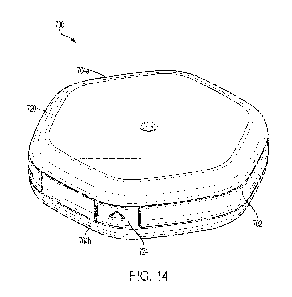
FIGS. 14-26 depict another example implementation of a container 700 in
accordance with one or
more embodiments of the disclosure, with FIGS. 19-24 depicting the base or
body portion 702 in greater
detail and FIGS. 25-26 depicting the covers 704a, 704b (collectively 704) in
greater detail. Generally, the
container 700 is similar to the other containers described above and includes
a base or body portion 702
defining a first internal space 740a accessible via a first opening 714a and a
second internal space 740b
accessible via a second opening 714b. The first internal space 740a may be
configured to hold a fresh
product, such as chewing tobacco, snus, or oral products, and the second
internal space 740b is configured to
hold another product, such as a used or waste product. In some
implementations, the body portion may
comprise a transparent or translucent material that allows a user to detect a
level of freshness, or other
-20-
CA 03191633 2023- 3-3
WO 2022/049545
PCT/IB2021/058074
condition, of the product contained therein without the need for opening the
container, which may negatively
impact the freshness of the product depending on the frequency of opening.
The container 700 includes first and second covers 704a, 704b configured to be
securely, but
removably, coupled to the body portion 702 so as to enclose their respective
internal spaces 740. As shown
in FIG. 16, the covers 704 and body portion 702 generally abut one another
when engaged and their
respective outer surfaces are substantially flush with one another, which
makes it difficult to separate the
parts. In some implementations, the covers 704 are secured to the body portion
702 via a snap or
interference fit, which provides additional resistance to separating the
parts. The engagement of the covers
704 and body portion 702 are shown in greater detail below.
As shown in the figures. the body portion 702 of the container 700 includes a
bottom wall 708
separating the first and second internal spaces 740, a primary sidewall 710
disposed about a peripheral edge
706 of the bottom wall 708 and extending upwardly (defining the first internal
space 740a) and downwardly
(defining the second internal space 740b) therefrom, and a secondary wall 726
comprising an upper edge
721a and a lower edge 72 lb. The secondary wall 726 is coupled to an outer
surface of the primary wall 710
and spaced outwardly therefrom to define a channel between the primary and
secondary walls 710, 726 such
that one or more portions 724 of the secondary wall flexes relative to the
primary wall upon application of a
force thereto.
As further shown in the figures, the container 700 includes the first cover
704a configured to
securely and removably engage the first opening 714a of the body portion 702,
where the first cover is
removable by flexing one of the one or more portions of the secondary wall 726
inwardly to expose an edge
738a of the first cover 704a. Similarly, the second cover 704b is configured
to securely and removably
engage the second opening 714b of the body portion 702 so that the second
cover 704b is removable by
flexing one of the one or more portions 724 of the secondary wall 726 inwardly
to expose an edge 738b of
the second cover 7041,.
With reference to FIGS. 18-20, in particular, the primary wall 710 of the body
portion 702
comprises a top edge 712a and a bottom edge 712b with the bottom wall 708
disposed proximate the bottom
edge 712b of the primary sidewall 710 so as to define two differently sized
internal spaces. Specifically, the
first internal space 740a comprises a first volume and the second internal
space 740b comprises a second
volume that is less than the first volume. The volume of the second internal
space 740b is generally shown
as much smaller than the first internal space 740a; however, the size of the
second internal space relative to
the first internal space may vary to suit a particular application. For
example, the sizes (i.e., volume) of first
and second internal spaces may be substantially equal or the volume of the
second internal space may be
about 90%, about 80%, about 70%, about 60%, about 50%, about 40%, about 30%,
about 20%, about 10%
of the volume of the first internal space 740a.
Referring to FIGS. 19-24, the structure and operation of the body portion 702
is described in greater
detail. The bottom wall 708 is shown having a circular shape; however, the
shape of the bottom wall 708
may vary to suit a particular application (e.g., type of product held by the
container, aesthetic purposes, etc.).
-21-
CA 03191633 2023- 3-3
WO 2022/049545
PCT/IB2021/058074
Similarly, the sidewall 710 depicted in the figures is a single, contiguous
circular wall; however, the wall
710 may comprise multiple wall portions or linear segments as would be
necessaly, for example, if the
container 700 had a non-cylindrical shape (e.g., rectangular, hexagonal,
octagonal, etc.). The sidewall 710
extends around the entire perimeter of the body portion 702 and has an inner
surface and an outer surface.
In certain implementations, the outer surface of the sidewall 710 includes a
plurality of raised structures 760
disposed thereon. The structures 760 may be provided to add strength to the
sidewall 710, for aesthetic
purposes, and/or other function. For example, in the depicted implementation,
the structures are disposed
equidistant about the outer surface and spaced apart to define a plurality of
grooves 749 about the outer
surface of the sidewall 710 that are configured to mate with rib-like
structures 748 within the covers 704 to
function as an alignment mechanism. As shown, the primaiy wall 710 of the body
portion 702 defines a
generally cylindrical shape and the secondary wall 726 defines a generally
hexagonal prismatic shape (see
FIG. 23); however, the shapes of the primary and secondary walls may vary to
suit a particular application.
In the depicted implementation, the sidewall 710 is the primary wall and the
secondary wall 726
surrounds the primary wall 710 and has an upper edge 721a and a lower edge 72
lb that are recessed relative
to the top edge 712a and the bottom edge 712b of the primary sidewall 710. The
secondary wall 726 is
coupled to the outer surface of the primary wall 710 via the one or more
lateral extensions 762 and spaced
outwardly therefrom and so as to define a channel 732 between the primary and
secondary walls such that
one or more portions (or flex features) 724 of the secondary wall flex
relative to the primary wall upon
application of a force thereto. Generally, the channel 732 allows the
secondary wall 726 to be flexed
inwardly (i.e., pressed towards the primary wall 710) upon application of a
force to certain portions thereof
(i.e., the flex features 724 described below), thereby providing access to an
edge 738 of either cover 704 to
assist in removing the cover 704. See FIGS. 18A and 18B for additional details
regarding the removal of the
covers 704. The amount of force required may vary to suit a particular
application and may depend on, for
example, the wall thicknesses, materials of construction, and/or the size of
the channel 732 or channel
openings. The container 700 may be configured to meet any minimum force
required to make the container
child proof, such as, for example, materials of construction and number of and
location of certain structural
features.
As disclosed above, the secondary wall 726 includes at least one flex feature
724 that assists in
separating the covers 704 from the body portion 702, but provides sufficient
resistance to the covers 704 and
body portion 702 being separated by a child. The flex feature 724 may be
formed in the primary wall 710 in
different manners. In the depicted implementation, the container 700 includes
four (4) flex features 724
disposed about the perimeter thereof, with two (2) configured for removal of
the first cover 704a and two (2)
configured for the removal of the second cover 704b. As shown, one of each of
the flex features 724 are
disposed proximate one another on generally opposing sides of the container
700 (see FIG. 23). However, in
other implementations the flex features may be spaced equidistant about the
body portion, specifically the
secondary wall 726.
-22-
CA 03191633 2023- 3-3
WO 2022/049545
PCT/IB2021/058074
The first flex feature 724a of the secondary wall 726 comprises a first tab
764a configured to flex
inwardly relative to the upper edge of the secondary wall 726 so as to expose
the edge of the first cover.
Generally, the first tab 764a is defined by a pair of vertical slits 766 that
extend from the upper edge 721a of
the secondary wall 726 to proximate the lower edge 72 lb of the secondary wall
so as to be hingedly coupled
to the secondary wall 726 at the lower edge 721b thereof. The third flex
feature 724c is disposed 180
degrees from and in opposition to the first flex feature 724a so that it may
be actuated (e.g., pressed)
simultaneously with the first flex feature 724a. The third flex feature 724c
is essentially identical to the first
flex feature insofar as it comprises a third tab 764c defined by a pair of
vertical slits 766 that extend from the
upper edge 721a of the secondary wall 726 to proximate the lower edge 721b of
the secondary wall so as to
be hingedly coupled to secondary wall 726 at the lower edge 72 lb and
configured to flex inwardly relative
to the upper edge of the secondary wall so as to expose the edge 738 of the
first cover 704a.
The second flex feature 724b of the secondary wall 726 comprises a second tab
764b configured to
flex inwardly relative to the lower edge 72 lb of the secondary wall so as to
expose the edge of the second
cover. Generally, the second tab 764b is defined by a pair of vertical slits
766 that extend from the lower
edge 72 lb of the secondary wall 726 to proximate the upper edge 721a of the
secondary wall so as to be
hingedly coupled to the secondary wall 726 at the upper edge 721a thereof. The
fourth flex feature 724d is
disposed 180 degrees from and in opposition to the second flex feature 724b so
that it may be actuated (e.g.,
pressed) simultaneously with the second flex feature 724b. The fourth flex
feature 724c is essentially
identical to the second flex feature insofar as it comprises a fourth tab 764d
defined by a pair of vertical slits
766 that extend from the lower edge 721b of the secondary wall 726 to
proximate the upper edge 721a of the
secondary wall so as to be hingedly coupled to the secondary wall 726 at the
upper edge 721a and
configured to flex inwardly relative to the lower edge of the secondary wall
so as to expose the edge of the
second cover.
FIGS. 24A and 24B depict the lateral extensions 762 in greater detail. As
shown in FIG. 24A, the
lateral extension 762 generally extends horizontally outward from the primary
wall 710 and couples to the
secondary wall 726 proximate a vertical midline of an inner surface thereof.
In the depicted implementation,
the lateral extension 762 and secondary wall are generally disposed midway up
the primary wall 710;
however, the exact placement of the secondary wall 726 may vary to suit a
particular application (e.g.,
depths of the internal spaces or covers). The lateral extension 762 is
generally shown as extending about the
entire perimeter of the body portion 702; however, in some implementations,
the lateral extension comprises
a plurality of non-contiguous segments that define one or more gaps where the
secondary wall 726 is not
directly coupled to the primary wall 710 (i.e., a portion of the secondary
wall "floats" relative to the primary
wall). Also shown in FIG. 24A, an inner surface of the secondary wall 726
comprises one or more retention
mechanisms 734 (e.g., one above and one below the lateral extension)
configured to engage a mating
structure on the first or second cover to secure the cover to the body portion
as discussed with respect to
FIGS. 18A and 18B.
-23-
CA 03191633 2023- 3-3
WO 2022/049545
PCT/IB2021/058074
FIG. 24B depicts the lateral extension 762 in the areas corresponding to the
flex features 724. As
shown, with respect to the first flex feature 724a, the lateral extension 762
comprises a first reverse
compound bend extending from proximate a midlinc of the primary wall 710 and
extending downwardly to
connect to the first tab 764a at the lower edge of the secondary wall 726.
Similarly, at the second flex
feature 724b, the lateral extension 762 comprises a second reverse compound
bend extending from
proximate a midline of the primary wall 710 and extending upwardly to connect
to the second tab 764b at
the upper edge of the secondary wall 726. The lateral extensions 762 at the
third and fourth flex features
724c, 724d are identical and located 180 degrees to the first and second flex
features 724a, 724b. Although
four flex features are described, it is possible for the container 700 to be
limited to two flex features, one for
each cover, or include any number of additional flex features 724 to suit a
particular application (e.g., the
size and/or shape of the container).
FIGS. 25A and 25B depict cross-sectional views of the covers 704 with the view
of FIG. 25B
rotated 90 degrees from the view of FIG. 25A. It should be noted that in the
depicted implementation, the
first and second covers 704 are identical so that only one of the covers is
described in detail. As shown, the
cover 704 includes a top wall 716, a primary sidewall 718 extending downwardly
from a peripheral edge
720 of the top wall 716, and an inner sidewall 742 extending downwardly from
the top wall and spaced
inwardly from the primary- sidewall 718 so as to define a receptacle 744
therebetween that is configured to
engage at least a portion of the primary wall 710 of the body portion 702. The
cover 704 is configured to
engage the body portion 702 via an interference fit or a snap fit. For
example, an outer surface of the
primary sidewall 718 comprises one or more retention mechanisms 734 configured
to engage the mating
structure on the body portion when the cover 704 is secured to the body
portion 702 (see FIG. 25B). In
addition, one or more ribs 748 may be provided on an inner surface of the
primary sidewall 718 that are
configured to engage a plurality of grooves 749 disposed on the outer surface
of the primary wall 710 so as
to assist in aligning the covers 704 and body portion 702. In some cases, the
ribs 748 provide additional
stiffening to the covers.
In the depicted implementation, the cover further comprises an outer sidewall
768 extending
outwardly from the peripheral edge 720 of the top wall 716 and configured to
sit substantially flush with an
outer surface of the secondary wall 726 of the body portion 702 when engaged.
The outer sidewall 768 and
the primary sidewall 718 define a plurality of gaps 770 spaced equidistant
about a perimeter of the cover
(see FIG. 26). Generally, at least a portion of the plurality of gaps 770 are
located so as to correspond to the
locations of the flex features 724 of the secondary wall 726 that flex
relative to the primary wall 710 upon
application of a force. In the depicted implementation, the container 700 has
an overall hexagonal shape and
the gaps 770 correspond to the corners of the hex shape.
Referring to FIGS. 17 and 18, the engagement between the body portion 702 and
covers 704 are
more clearly depicted. As shown and previously described, the body portion 702
includes a bottom wall 708
and a primary wall 710 spanning the bottom wall 708 and defining two internal
spaces 740. The body
portion 702 includes a secondary wall 726 that defines one or more flex
features 724. The first (upper) and
-24-
CA 03191633 2023- 3-3
WO 2022/049545
PCT/IB2021/058074
second (lower) covers 704 include top walls 716 and primary, inner, and outer
sidewalls 718, 742, 768
extending downwardly therefrom and configured to engage their respective
openings 714 of the internal
spaces. In the depicted implementation, the primary wall 710 and primary
sidcwall 718 include mating
structure 134 to enable a snap fit between the covers and the body portion.
The bottom edges 738 of the
covers 704 abut against the top/bottom edges 721 of or recess in the body
portion primary wall 710 and, in
some embodiments, the outer surface of the covers 704 sit flush with or
slightly inward of the outer surface
of the secondary wall 726 to make it difficult to engage with and remove the
covers 704 from the body
portion 702. See FIGS. 18A and 18B.
FIG. 18A illustrates one of each of the flex features 724 for removing the
bottom cover 704b
(feature 724b) and the top cover 704a (feature 724b), with the enlarged view
(FIG. 18B) depicting the
container rotated approximately 90 degrees to depict engagement between the
walls at a location without a
flex feature 724. Specifically, the enlarged view depicts the primary
sidewalls 718 of the covers 704
disposed within the channel 732 defined by the primary wall 710 and the
secondary wall 726 of the body
portion 702 and retained therein via the retention mechanisms 734.
To remove one of the covers 704, a user applies a force (F1) to an outer
surface of the secondary
wall 726 (i.e., presses the secondary wall 726) at one or more flex features
724, thereby exposing the edge
738 of the cover primary sidewall 718, as shown in FIG. 18A. This allows the
user to apply a force (F2) to
the bottom edge 738 (e.g., via the use of a tool or finger nail) sufficient to
overcome the holding force of the
interference or snap fit, thereby separating the cover 704 from the body
portion 702. In some
implementations, the user may press two opposing flex features 724 (e.g., the
first and third tabs 764a, 764c)
simultaneously (e.g., with the user's thumb and third finger) to be able to
apply the removing force F2 to
two locations on the cover edge 738. Once the user releases (i.e., removes the
applied force) the flex
feature(s) 724 and the body portion 702 returns to its neutral/normal or
unflexed configuration. The cover
704 can be reattached to the body portion 702 by pushing the cover back onto
the body portion with
sufficient force to reengage the interference or snap fit, which should be
evident once the cover and body
portion are back in an abutting configuration as described above.
FIGS. 27-37 depict yet another example implementation of a container 800 in
accordance with one
or more embodiments of the disclosure and similar to container 700 described
above, with FIGS. 32-37
depicting the base or body portion 802 in greater detail. As shown, the
container 800 includes the same or
substantially similar covers 804 to the covers 704 described above.
Accordingly, the covers 804 will not be
discussed in any detail with respect to this implementation of the container
800. Generally, the container
800 is similar to the other containers described above and includes a base or
body portion 802 defining a
first internal space 840a accessible via a first opening 814a and a second
internal space 840b accessible via a
second opening 814b. The first internal space 840a may be configured to hold a
fresh product, such as
chewing tobacco, snus, or oral products, and the second internal space 840b is
configured to hold another
product, such as a used or waste product. The container 800 includes first and
second covers 804a, 804b
configured to be securely, but removably, coupled to the body portion 802 so
as to enclose their respective
-25-
CA 03191633 2023- 3-3
WO 2022/049545
PCT/IB2021/058074
internal spaces 840. As shown in FIG. 29, the covers 804 and body portion 802
generally abut one another
when engaged and their respective outer surfaces are substantially flush with
one another, which makes it
difficult to separate the parts. In some implementations, the covers 804 are
secured to the body portion 802
via a snap or interference fit, which provides additional resistance to
separating the parts. The engagement
of the covers 804 and body portion 802 are described in greater detail below.
As shown in the figures, the body portion 802 of the container 800 includes a
bottom wall 808
separating the first and second internal spaces 840, a sidewall 810 disposed
about a peripheral edge 806 of
the bottom wall 808 and extending upwardly (defining the first internal space
840a) and downwardly
(defining the second internal space 840b) therefrom, and a secondary wall 826
comprising an upper edge
821a and a lower edge 82 lb. The secondary wall 826 is coupled to an outer
surface of the primary wall 810
and spaced outwardly therefrom to define a channel between the primary and
secondary walls 810, 826 such
that one or more portions 824 of the secondary wall flexes relative to the
primary wall 810 upon application
of a force thereto.
As further shown in the figures, the container 800 includes the first cover
804a configured to
securely and removably engage the first opening 814a of the body portion 802,
where the first cover is
removable by flexing one of the one or more portions of the secondary wall 826
inwardly to expose an edge
838a of the first cover 804a. Similarly, the second cover 804b is configured
to securely and removably
engage the second opening 814b of the body portion 802 so that the second
cover 804b is removable by
flexing one of the one or more portions 824 of the secondary wall 826 inwardly
to expose an edge 838b of
the second cover 804b.
With reference to FIGS. 32-34, in particular, the sidewall 810 of the body
portion 802 comprises a
top edge 812a and a bottom edge 812b with the bottom wall 808 disposed
proximate the bottom edge 812b
of the sidewall 810 so as to define two differently sized internal spaces.
Specifically, the first internal space
840a comprises a first volume and the second internal space 840b comprises a
second volume that is less
than the first volume. The volume of the second internal space 840b is
generally shown as much smaller
than the first internal space 840a; however, the size of the second internal
space relative to the first internal
space may vary to suit a particular application. For example, the sizes (i.e.,
volume) of first and second
internal spaces may be substantially equal or the volume of the second
internal space may be about 90%,
about 80%, about 70%, about 60%, about 50%, about 40%, about 30%, about 20%,
about 10% of the
volume of the first internal space 840a.
Referring to FIGS. 31-37, the structure and operation of the body portion 802
is described in greater
detail. The bottom wall 808 is shown having a circular shape; however, the
shape of the bottom wall 808
may vary to suit a particular application (e.g., type of product held by the
container, aesthetic purposes, etc.).
Similarly, the sidewall 810 depicted in the figures is a single, contiguous
circular wall; however, the wall
810 may comprise multiple wall portions or linear segments as would be
necessary, for example, if the
container 800 had a non-cylindrical shape (e.g., rectangular, hexagonal,
octagonal, etc.). The sidewall 810
extends around the entire perimeter of the body portion 802 and has an inner
surface and an outer surface.
-26-
CA 03191633 2023- 3-3
WO 2022/049545
PCT/IB2021/058074
In certain implementations, the outer surface of the sidewall 810 includes a
plurality of raised structures 860
disposed thereon. The structures 860 may be provided to add strength to the
sidewall 810, for aesthetic
purposes, and/or other function. For example, in the depicted implementation,
the structures arc disposed
equidistant about the outer surface and spaced apart to define a plurality of
grooves 849 about the outer
surface of the sidewall 810 that are configured to mate with rib-like
structures 848 within the covers 804 to
function as an alignment mechanism. As shown, the primary wall 810 of the body
portion 802 defines a
generally cylindrical shape and the secondary wall 826 defines a generally
hexagonal prismatic shape (see
FIG. 37); however, the shapes of the primary and secondary walls may vary to
suit a particular application.
In the depicted implementation, the sidewall 810 is the primary wall and the
secondary wall 826
surrounds the primary wall 810 and has an upper edge 821a and a lower edge 82
lb that are recessed relative
to the top edge 812a and the bottom edge 812b of the primary wall 810. The
secondary wall 826 is coupled
to the outer surface of the primary wall 810 via one or more lateral
extensions 862 and spaced outwardly
therefrom so as to define a channel 832 between the primary and secondary
walls such that one or more
portions (or flex features) 824 of the secondary wall flex relative to the
primary wall upon application of a
force thereto. Generally, the channel 832 allows the secondary wall 826 to be
flexed inwardly (i.e., pressed
towards the primary wall 810) upon application of a force to certain portions
thereof (flex features 824
described below), thereby providing access to an edge 838 of either cover 804
to assist in removing the
cover 804. See FIGS. 32A and 32B for additional details regarding the removal
of the covers 804. The
amount of force required may vary to suit a particular application and may
depend on, for example, the wall
thicknesses, materials of construction, and/or the size of the channel 832 or
channel openings. The container
800 may be configured to meet any minimum force required to make the container
child proof, such as, for
example, materials of construction and number of and location of certain
structural features.
As disclosed above, the secondary wall 826 includes at least one flex feature
824 that assists in
separating the covers 804 from the body portion 802, but provides sufficient
resistance to prevent the covers
804 and body portion 802 from being separated by a child. The flex feature 824
may be formed in the
secondary wall 826 in different manners. In the depicted implementation, the
container 800 includes two (2)
flex features 824 disposed proximate one another and on one side of the
container 800 (see FIGS. 29 and
33), where both flex features 824 are configured for removal of the first
cover 804a or the second cover
804b. Although two flex features are described, it is possible for the
container 800 to include any number of
additional flex features 824 to suit a particular application (e.g., the size
and/or shape of the container) and
the flex features may be spaced equidistant about the body portion,
specifically the secondary wall 826.
FIGS. 32A, 32B, and 37 depict the lateral extensions 862 and flex features 824
in greater detail. As
shown, the lateral extension 862 generally extends horizontally outward from
the primary wall 810 and
couples to the secondary wall 826 proximate a vertical midline of an inner
surface thereof (left side of FIG.
32A). In the depicted implementation. the lateral extension 862 and secondary
wall 826 are generally
disposed midway up the primary wall 810; however, the exact placement of the
secondary wall 826 may
vary to suit a particular application (e.g., depths of the internal spaces or
covers). The lateral extension 862
-27-
CA 03191633 2023- 3-3
WO 2022/049545
PCT/IB2021/058074
is generally shown as extending about a substantial portion of the perimeter
of the body portion 802;
however, in some implementations, the lateral extension comprises a plurality
of non-contiguous segments
that define one or more gaps where the secondary wall 826 is not directly
coupled to the primary wall 810.
As shown in FIG. 37, there is a portion 872 of the container 800 where the
secondary wall 826 is not
attached to the primary wall 810 of the body portion 802 (i.e., that portion
of the secondary wall 826 "floats"
relative to the primary wall 810). This arrangement provides for two floating
corners of the secondary wall
that form first and second flex features 824a, 824b. The flex features 824a of
the secondary wall 826
include a tactile feature 874, such as, for example, a protuberance or other
minimally raised structure that a
user can feel when gripping the container 800. The feature 874 provides for a
press point for actuating the
flex feature 824 (application of a force thereto) which will deflect the flex
feature section of the secondary
wall 826 towards the primary wall 810, thereby exposing the edges 838 of the
covers 804.
Referring to FIG. 32A, the engagement between the body portion 802 and covers
804 is more
clearly depicted. As shown and previously described, the body portion 802
includes a bottom wall 808 and a
primary wall 810 spanning the bottom wall 808 and defining two internal spaces
840. The body portion 802
includes a secondary wall 826 that defines one or more flex features 824. The
first (upper) and second
(lower) covers 804 include top walls 816 and primary, inner, and outer
sidewalls 818, 842, 868 extending
downwardly therefrom and configured to engage their respective openings 814 of
the internal spaces. In the
depicted implementation, the primary wall 810 and primary sidewall 818 include
mating structure 834 to
enable a snap fit between the covers 804 and the body portion 802. The bottom
edges 838 of the covers 804
approximately abut against the top and bottom edges 821 of or recess in the
body portion primary wall 810
and, in some embodiments, the outer surfaces of the covers 804 sit flush with
or slightly inward of the outer
surface of the secondary wall 826 to make it difficult to engage with and
remove the covers 804 from the
body portion 802.
FIG. 32A illustrates operation of one of the flex features 824 for removing
the bottom cover 804b
and the top cover 804a, with the enlarged view depicting the container rotated
approximately 90 degrees to
depict engagement between the walls 810, 818 at a location without a flex
feature 824. Specifically, the
enlarged view (FIG. 32B) depicts the primary sidewalls 818 of the covers 804
disposed within the channel
832 defined by the primary wall 810 and the secondary wall 826 of the body
portion 802 and retained
therein via the retention mechanisms 834.
To remove one of the covers 804, a user applies a force (F1) to an outer
surface of the secondary
wall 826 (i.e., presses the secondary wall 826) at one or more flex features
824, thereby exposing the edges
838 of the cover primary sidewalls 818, as shown in FIG. 32A. This allows the
user to apply a force (F2) to
the edge 838 (e.g., via the use of a tool or finger nail) sufficient to
overcome the holding force of the
interference or snap fit, thereby separating the cover 804 from the body
portion 802. In some
implementations, the user may press both flex features 824 simultaneously to
be able to apply the removing
force F2 to two locations on the cover edge 838. Once the user releases (i.e.,
removes the applied force) the
flex feature(s) 824 and the body portion 802 returns to its neutral/normal or
unflexed configuration. The
-28-
CA 03191633 2023- 3-3
WO 2022/049545
PCT/IB2021/058074
cover 804 can be reattached to the body portion 802 by pushing the cover back
onto the body portion with
sufficient force to reengage the interference or snap fit, which should be
evident once the cover and body
portion are back in an abutting configuration as described above.
FIGS. 38-46 depict yet another example implementation of a container 900 in
accordance with one
or more embodiments of the disclosure and substantially similar to container
800 described above, except
with only a single internal space and a single cover. The cover 904 is
identical to covers 704, 804 described
above and will not be described again; however, there are two alternative
versions of the cover 1004, 1104
depicted in and described with respect to FIGS. 47A and 47B. Specifically, the
container 900 is similar to
the other containers described above and includes a base or body portion 902
defining an internal space 940
accessible via an opening 914. The internal space 940 may be configured to
hold a fresh product, such as
chewing tobacco, snus, or oral products.
The container 900 includes a cover 904 configured to be securely, but
removably, coupled to the
body portion 902 so as to enclose the internal space 940. As shown in FIGS. 38
and 40, the cover 904 and
body portion 902 generally abut one another when engaged and their respective
outer surfaces are
substantially flush with one another, which makes it difficult to separate the
parts. In some implementations,
the cover 904 is secured to the body portion 902 via a snap or interference
fit, which provides additional
resistance to separating the parts. The engagement of the cover 904 and body
portion 902 are described in
greater detail below.
As shown in the figures. the body portion 902 of the container 900 includes a
bottom wall 908, a
sidewall 910 disposed about a peripheral edge 906 of the bottom wall 908 and
extending upwardly (defining
the internal space 940), and a secondary wall 926 comprising an upper edge
921a. The secondary wall 926
is coupled to an outer surface of the primary wall 910 and spaced outwardly
therefrom to define a channel
932 between the primary and secondary walls 910, 926 such that one or more
portions 924 of the secondary
wall flexes relative to the sidewall 910 upon application of a force thereto.
As further shown in the figures,
the container 900 includes the cover 904 configured to securely and removably
engage the opening 914 of
the body portion 902, where the cover is removable by flexing one of the one
or more portions of the
secondary wall 926 inwardly to expose an edge 938 of the cover 904.
Referring to FIGS. 40-46, the structure and operation of the body portion 902
is described in greater
detail. The bottom wall 908 is shown having a circular shape; however, the
shape of the bottom wall 908
may vary to suit a particular application (e.g., type of product held by the
container, aesthetic purposes, etc.).
Similarly, the sidewall 910 depicted in the figures is a single, contiguous
circular wall; however, the sidewall
910 may comprise multiple wall portions or linear segments as would be
necessary, for example, if the
container 900 had a non-cylindrical shape (e.g., rectangular, hexagonal,
octagonal, etc.). The sidewall 910
extends around the entire perimeter of the body portion 902 and has an inner
surface and an outer surface.
In certain implementations, the outer surface of the sidewall 910 includes a
plurality of raised structures 960
disposed thereon. The structures 960 may be provided to add strength to the
sidewall 910, for aesthetic
purposes, and/or other function. For example, in the depicted implementation,
the structures 960 are
-29-
CA 03191633 2023- 3-3
WO 2022/049545
PCT/IB2021/058074
disposed equidistant about the outer surface and spaced apart to define a
plurality of grooves 949 about the
outer surface of the sidewall 910 that are configured to mate with rib-like
structures 948 within the cover
904 to function as an alignment mechanism. As shown, the sidewall 910 of the
body portion 902 defines a
generally cylindrical shape and the secondary wall 926 defines a generally
hexagonal prismatic shape (see
FIGS. 43 and 46); however, the shapes of the primary and secondary walls may
vary to suit a particular
application.
In the depicted implementation, the sidewall 910 is the primary wall and the
secondary wall 926
surrounds the primary wall 910 and has an upper edge 921 that is recessed
relative to the top edge 912 of the
primal)/ wall 910. The secondary wall 926 is coupled to the outer surface of
the primary wall 910 via one or
more lateral extensions 962 and spaced outwardly therefrom and so as to define
a channel 932 between the
primary and secondary walls such that one or more portions (or flex features)
924 of the secondary wall flex
relative to the primary wall upon application of a force thereto, lathe
depicted implementation, the lateral
extension 962 extends from the peripheral edge 906 of the bottom wall 908;
however, in some
implementations, the secondary wall 926 extends directly from the bottom wall
908 and may be formed as a
single piece therewith.
Generally, the channel 932 allows the secondary wall 926 to be flexed inwardly
(i.e., pressed
towards the primary wall 910) upon application of a force to certain portions
thereof (i.e., flex features 924
described below), thereby providing access to an edge 938 of the cover 904 to
assist in removing the cover
904. See FIGS. 42A and 42B for additional details regarding the removal of the
cover 904. The amount of
force required may vary to suit a particular application and may depend on,
for example, the wall
thicknesses, materials of construction, and/or the size of the channel 932 or
channel openings. The container
900 may be configured to meet any minimum force required to make the container
child proof, such as, for
example, materials of construction and number of and location of certain
structural features.
As disclosed above, the secondary wall 926 includes at least one flex feature
924 that assists in
separating the covers 904 from the body portion 902, but provides sufficient
resistance to prevent the covers
904 and body portion 902 from being separated by a child. The flex feature 924
may be formed in the
secondary wall 926 in different manners. In the depicted implementation, the
container 900 includes two (2)
flex features 924 disposed proximate one another and on one side of the
container 900 (see FIGS. 38, 43,
and 46). Although two flex features are described, it is possible for the
container 900 to include any number
of additional flex features 924 to suit a particular application (e.g., the
size and/or shape of the container)
and the flex features may be spaced equidistant about the body portion,
specifically the secondary wall 926.
FIGS. 42 and 46 depict the lateral extensions 962 and flex features 924 in
greater detail. As shown,
the lateral extension 962 generally extends horizontally outward from the
primary wall 810 / peripheral edge
906 of the bottom wall 908 and couples to the secondary wall 826. The lateral
extension 962 is generally
shown as extending about a substantial portion of the perimeter of the body
portion 902; however, in some
implementations, the lateral extension comprises a plurality of non-contiguous
segments that define one or
more gaps 976 where the secondary wall 826 is not directly coupled to the
primary wall 810. As shown in
-30-
CA 03191633 2023- 3-3
WO 2022/049545
PCT/IB2021/058074
FIG. 46, there is a portion 972 of the container 900 where the secondary wall
926 is not attached to the
primary wall 910 of the body portion 902 (i.e., that portion of the secondary
wall 926 "floats" relative to the
primary wall 910). This arrangement provides for two floating corners of the
secondary wall that form first
and second flex features 924a, 924b. The flex features 924a of the secondary
wall 826 include a tactile
feature 974, such as, for example, a protuberance or other minimally raised
structure that a user can feel
when gripping the container 900. The feature 974 provides a press point for
actuating the flex feature 924
(application of a force thereto) which will deflect the flex feature section
of the secondary wall 926 towards
the primary wall 910, thereby exposing the edge 938 of the cover 904. FIGS. 44
and 45 depict bottom views
of the body portion 902 so as to illustrate the gaps 976 formed by the absence
of the lateral extension 962
and/or removal of a portion of the secondary wall 926 extending from the
peripheral edge 906 of the bottom
wall 908. In the implementations of the containers 700, 800 described above,
the gaps are not visible when
assembled, because the second cover is positioned over the gaps.
Referring to FIG. 42A, the engagement between the body portion 902 and cover
904 is more clearly
depicted. As shown and previously described, the body portion 902 includes a
bottom wall 908 and a
primary wall 910 extending upwardly therefrom to define the internal space
940. The body portion 902
includes a secondary wall 926 that defines one or more flex features 924. The
cover 904 includes a top wall
916 and primary, inner, and outer sidewalls 918, 942, 968 extending downwardly
therefrom and configured
to engage the opening 814 of the internal space. In the depicted
implementation, the primary wall 910 and
primary sidewall 918 include mating structure 934 to enable a snap fit between
the cover 904 and the body
portion 902. The bottom edge 938 of the cover 904 approximately abuts a top
edge of or recess in the body
portion primary wall 910 and, in some embodiments, the outer surface of the
cover 904 sits flush with or
slightly inward of the outer surface of the secondary wall 926 to make it
difficult to engage with and remove
the covers 904 from the body portion 902.
FIG. 42A illustrates operation of one of the flex features 924 for removing
the cover 904 (feature
924a), with the enlarged view depicting the container rotated approximately 90
degrees to depict
engagement between the walls at a location without a flex feature 924.
Specifically, the enlarged view (FIG.
42B) depicts the primary sidewall 918 of the cover 904 disposed within the
channel 932 defined by the
primary wall 910 and the secondary wall 926 of the body portion 902 and
retained therein via the retention
mechanisms 834.
To remove the cover 904, a user applies a force (F1) to an outer surface of
the secondary wall 926
(i.e., presses the secondary wall 926) at one or more flex features 924,
thereby exposing the edge 938 of the
cover, as shown in FIG. 42A. This allows the user to apply a force (F2) to the
edge 938 (e.g., via the use of
a tool or finger nail) sufficient to overcome the holding force of the
interference or snap fit, thereby
separating the cover 904 from the body portion 902. In some implementations,
the user may press both flex
features 924 simultaneously to be able to apply the removing force F2 to two
locations on the cover edge
938. Once the user releases (i.e., removes the applied force) the flex
feature(s) 924 and the body portion 902
returns to its neutral/normal or unflexed configuration. The cover 904 can be
reattached to the body portion
-31-
CA 03191633 2023- 3-3
WO 2022/049545
PCT/IB2021/058074
902 by pushing the cover back onto the body portion with sufficient force to
reengage the interference or
snap fit, which should be evident once the cover and body portion are back in
an abutting configuration as
described above.
FIGS. 47A and 47B depict two alternative covers 1004, 1104 that may be
securely, but removably,
coupled to the body portion 902 so as to enclose the internal space 940.
Generally, both covers include a top
wall 1016, 1116, similar to those described above, along with similar side
walls and retaining structures.
However, these covers 1004, 1104 include hatches 1054, 1056 disposed in the
top walls 1016, 1116 thereof
Specifically, and as shown in FIG. 47A, the hatch 1054 extends across
approximately 50% of the top surface
or wall 1016 of the cover 1004. As shown in FIG. 47B, the hatch 1154 extends
across substantially the
entire top surface or top wall 1116 of the cover 1104. In each cover 1004,
1104 an opening 1052, 1152 is
formed in the top cover 1016, 1116 that generally corresponds to the shape and
size of the hatch, but may
include other shapes and sizes to suit a particular application. The hatches
1054, 1154 are hingedly coupled
to their respective covers via a hinge mechanism 1058, 1158, which may
include, for example, a hinge
incorporated via insert molding or a thinned or weakened section of the cover
between the hatch and top
wall.
In some implementations, the top walls 1016, 1116 include recesses 1078, 1178
disposed about the
openings 1052, 1152 and configured to receive the hatches 1054, 1154.
Additionally, the hatches 1054, 1154
may include stiffening ribs 1056, 1156 or similar structures disposed on a
bottom or interior surface of the
hatches to add strength thereto and/or enhance the interface between the hatch
1054, 1154 and the recesses
1078, 1178. The hatches 1054, 1154 may be provided as alternative methods of
accessing the contents of
the body portion without removing the covers 1004, 1104 and may include their
own child-resistant feature
(e.g., flush mounting, interference fit, stiffness of the hinge mechanisms,
etc.).
The additional implementations of the containers 700, 800, 900 described above
may be
manufactured from any of the materials or by any of the methods described
herein.
In various implementations of the containers described herein, the containers
may include additional
features, such as a barrier film or membrane configured to cover the opening
in the body portion, thereby
enclosing the internal space. By way of example, the barrier film may comprise
a foil or a film (e.g., a
polymer film) and/or may contain a material selected and configured to be
substantially fluid-impervious so
as to prevent the flow of fluids from the internal space to an external
environment or allow the transmission
of gasses therethrough (e.g., diffusion of oxygen into the internal space) to
maintain the freshness of the
tobacco-containing material by supporting the health of aerobic microbes
within the tobacco-containing
material. Another feature that may be included is a vent mechanism disposed in
the body portion, the cover,
or both to help regulate an internal pressure or other environmental condition
within the container.
Many modifications and other implementations of the disclosure will come to
mind to one skilled in
the art to which this disclosure pertains having the benefit of the teachings
presented in the foregoing
descriptions and the associated figures. Therefore, it is to be understood
that the disclosure is not to be
limited to the specific implementations disclosed herein and that
modifications and other implementations
-32-
CA 03191633 2023- 3-3
WO 2022/049545
PCT/IB2021/058074
are intended to be included within the scope of the appended claims. Although
specific terms are employed
herein, they are used in a generic and descriptive sense only and not for
purposes of limitation.
-33-
CA 03191633 2023- 3-3