Note : Les descriptions sont présentées dans la langue officielle dans laquelle elles ont été soumises.
CA 03191861 2023-02-15
1
BIN STORAGE SYSTEM WITH ROBOTS RUNNING ON COVERS
1. Field of the invention
The field of the invention is that of warehouse logistics, and in particular
the
automatic storage and retrieval of products.
More specifically, the invention relates to a system for storing bins stacked
in columns.
The invention has particular application in the storage of foodstuffs at
controlled temperatures, for example in a refrigerated or frozen environment.
2. State of the art
Automated structures for storing bins containing products in a three-
dimensional grid are known, for example from document N0317366 81, in
which the bins are stored on top of each other in columns to which rails have
been attached to allow the movement of robots to pick up or drop off one or
more bins in a column and transport them on the grid-like rail network to
another storage column or collection point, where for example the bins are
transferred onto a conveyor or into a lift.
To ensure the storage of fresh or frozen food products, it has been
suggested, for example in US2018/0128532 Al, to create temperature-
controlled storage areas, grouping together several columns in which the
temperature is maintained respectively at positive cold or a temperature of
approximately -18 C. This area is thermally insulated around its perimeter and
covers made of insulating material are placed on each of the columns of the
temperature-controlled storage area between the robot circulation rails.
A shortcoming of this known technique is the handling of the covers. The
covers must be removed and placed on top of other covers to gain access to
the bins stored in a temperature-controlled column, and then replaced between
the rails above the column, or dedicated robots must be used to handle the
covers while another robot picks up or places bins in a temperature-controlled
column. As a result, these techniques are complex to implement and costly. In
addition, the different handling of the covers increases the time needed to
remove a bin from the storage structure.
Date Recue/Date Received 2023-02-15
CA 03191861 2023-02-15
2
In addition, the products in the bins become warm during the numerous
manipulations of the covers, which is undesirable.
In order to reduce the exposure time of the products to the ambient
temperature of the warehouse, it was thought to also maintain a controlled
temperature in the circulation area of the robots, above the storage columns
of
a temperature controlled area.
A shortcoming of this known technique is that condensation can occur on
the electronic circuits of the robots when they move from one area to another
area with a different temperature, which can damage them or hinder their
proper functioning.
In order to overcome this shortcoming, it was suggested in
W02019/001816 Al to partition the different temperature zones and to use a
lift to transport bins from one zone to another.
A shortcoming of this technique is that it is expensive and complex to
implement.
3. Objects of the invention
The invention therefore aims to overcome the above-mentioned
shortcomings of the state of the art.
More specifically, the aim of the invention is to provide a technique that
allows quick and easy removal of bins.
It is also an object of the invention to provide such a technique that limits
the heating of the products stored in the bins during their handling.
A further object of the invention is to provide such a technique which is
simple to implement, and of low cost.
In particular, the aim of the invention is to provide a storage technique that
allows products to be stored at different temperatures in the same facility.
A further object of the invention is to provide such a technique that is
reliable.
4. Statement of the invention
These objects, as well as others that will appear later, are achieved by
means of a bin storage system comprising a plurality of storage columns of
Date Recue/Date Received 2023-02-15
CA 03191861 2023-02-15
3
substantially rectangular cross-section, said columns being configured to
receive a vertical stack of bins, the upper contours of said storage columns
forming a grid, and at least one robot operating above said grid, capable of
picking up, transporting and depositing bins, said robot comprising means for
gripping and lifting at least one bin and being equipped with wheels.
According to the invention, such a system comprises a plurality of
removable covers above said grid, said covers being substantially contiguous
with the covers adjacent thereto and extending substantially over the entire
surface of a cell of said grid and said covers forming a traffic platform for
said
robot, and said robot has means for pushing, pulling and/or lifting said
covers
to change the position of said covers to free access to the upper part of said
columns.
Thus, in a novel way, the invention proposes to use covers to form a rolling
surface for the robots, on which the robots can move freely in all directions
or
along predefined paths, for example by running in guides formed in the covers,
which limits infrastructure costs, and in the case where the robots can move
freely, allows greater mobility and significantly increases the speed of
movement of the robots between two distant positions on the grid.
It should be noted that the covers can be tilted vertically, pushed or pulled
substantially horizontally to slide over or under other covers, or lifted by
the
robot to provide access to the columns, without going beyond the scope of the
invention.
Furthermore, the term "removable" is used in the context of the invention
in its general sense, i.e. the cover can be moved, either translationally or
rotationally, or a combination of both.
In an advantageous embodiment of the invention, each of said covers is
pivotally mounted along a horizontal axis between a horizontal position in
which
it closes off the top of a column and a vertical position in which access to
the
top of the column is released, and said pushing, pulling and/or lifting means
are adapted to push a free end of a cover to cause it to tilt upwards.
Date Recue/Date Received 2023-02-15
CA 03191861 2023-02-15
4
Thus, by pivotally mounting covers, the robots can easily access the bins
stored in the columns below them by tilting them upwards by simply pushing
or pulling on their free end.
In a variation of this particular embodiment of the invention, said means for
pushing, pulling and/or lifting said covers comprise a member projecting from
the chassis of said robot for engaging the underside of the cover and pushing
it to pivot upwards to said vertical position.
In a particular embodiment of the invention, said covers are pivotally
mounted along two parallel horizontal axes extending substantially at two
opposite edges of said cover.
This allows the covers to move to one side or the other, allowing the robots
to approach the covers from either side, which can reduce the distance the
robots travel and free up a path for another robot to move through.
In a particular embodiment of the invention, at least one of said covers is
slidably mounted between a first position in which it closes off the top of a
column and a second position, in which said cover is housed under a cover
adjacent thereto in said first position, thereby freeing access to the top of
that
column.
In a particular embodiment of the invention, said sliding cover has first and
second pairs of laterally projecting fingers and comprises a first pair of
finger
guiding slides of said first pair of fingers extending on opposite edges of
the
column closed by said sliding cover in said first position and a second pair
of
finger guiding slides of said second pair of fingers extending on opposite
edges
of an adjacent column of said column closed by said sliding cover in said
first
position, located in the extension of said first pair of slides.
In an advantageous embodiment of the invention, said covers have a layer
of thermal insulation and said storage columns under said covers are
temperature controlled volumes.
The storage system allows products to be stored in all or part of its volume
at one or more controlled temperatures, while avoiding frigorie loss.
Date Recue/Date Received 2023-02-15
CA 03191861 2023-02-15
In a particular embodiment of the invention, at least two of said storage
columns are at different controlled temperatures.
This means that positive cold products, frozen products and products at
room temperature in the warehouse, for example, can be stored in the same
5 system.
According to a particular aspect of the invention, said means for pulling
and/or pushing a free end of a cover comprise a finger adapted to cooperate
with a housing formed in one of said covers.
Preferably, said robot has at least two driving wheels.
In a particular embodiment of the invention, said robot has three or four
driving wheels.
According to an advantageous embodiment of the invention, said means for
gripping and lifting at least one container comprise a frame capable of
sliding
around said bins, equipped with means of attachment to a container and means
of vertical displacement of said frame under the chassis of said robot.
In the context of the invention, the term "frame" means a device, such as
a chassis, for enclosing a container on at least three sides.
In a particular embodiment of the invention, said fastening means comprise
hooks or claws.
In a particular embodiment of the invention, a system as described above
comprises at least one column for depositing said bins and means for removing
said bins from said deposit column.
This means that the robots can easily return the stored bins.
In a particular embodiment of the invention, a first pair and a second pair
of parallel rails or guiding slides are formed in the upper portion of said
bonnet,
the rails or guiding slides of said second pair of parallel rails or guiding
slides
being perpendicular to the rails or guiding slides of said first pair, and in
that
said robot is equipped with wheels suitable for running on rails or guiding
slides
and runs on either of said pairs of rails or guiding slides.
Thus, by building the guiding slides directly into the covers, the costs of
implementing the storage system are reduced.
Date Recue/Date Received 2023-02-15
CA 03191861 2023-02-15
6
5. List of figures
Other features and advantages of the invention will become clearer from
the following description of two embodiments of the invention, given merely as
illustrative and non-limiting examples, and of the appended drawings, of
which:
- Figure 1 is a
perspective view of an example of an embodiment of a
storage system according to the invention;
- Figure 2 is a detail view of a cover of the storage system shown in
reference to Figure 1, in the upright position;
- Figure 3 illustrates a step of picking a stack of bins by a robot of the
system shown with reference to Figure 1, in which the robot positions
itself opposite the cover to be lifted to pick the stack of bins;
- Figure 4 illustrates a step in picking up a stack of bins by a robot of
the
system shown in Figure 1, in which the robot engages a finger in the
cover to lift it;
- Figure 5 illustrates a step in picking up a stack of bins by a robot of the
system shown in Figure 1, in which the robot completes pushing on the
underside of the cover to tilt it upwards;
- Figure 6 illustrates a step of picking a stack of bins by a robot of the
system shown with reference to Figure 1, in which the robot is positioned
above a column and actuates the sliding of a frame downwards around
the stack in order to pick the stack of bins;
- Figure 7 is a partial view of a robot circulation platform of another
example of an embodiment of a storage system of the invention, in
which all the covers close off columns;
- Figure 8 is a detail view of the platform shown with reference to Figure
7, when the front of one of the covers is tilted downwards by a robot to
be able to slide it under the cover in front of it;
- Figure 9 is a view of the platform shown with reference to Figures 7 and
8, as the cover begins to slide under the cover in front of it.
- Figure 10 is a view of the platform shown with reference to Figures 7
and 9, when the cover slides flat under the cover in front of it.
Date Recue/Date Received 2023-02-15
CA 03191861 2023-02-15
7
6. Detailed description of the invention
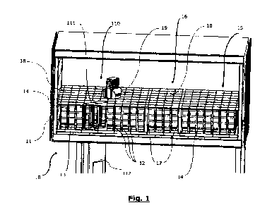
Figure 1 illustrates, in a perspective view, an example of an automated
storage system according to the invention implemented within a food storage
warehouse.
This system 10 comprises a storage facility 11 formed by uprights 12
arranged in the plane of a grid, delimiting juxtaposed storage columns, or
cells,
13 of rectangular cross-sections for storing bins 14 stacked on top of each
other.
In this particular embodiment of the invention, the facility 11 is divided
into
three zones: a first zone 15 for keeping the contents of the bins cold, a
second
zone 16 for receiving bins containing frozen products and a third zone 110 for
receiving bins that can be stored at the ambient temperature of the warehouse.
Vertical dividing walls 17 of thermally insulating material extending over the
entire height of the columns are mounted between the first 15 and the second
zone 16 and between the second and the third zone 110. In addition, the outer
edges of the first zone 15 are covered with a protective thermal insulation
layer.
Above the columns of the first 15, second 16 and third 110 zones, covers
18 are pivotally mounted, which are substantially contiguous with each other
and allow the top opening of the columns 13 to be closed. When tilted flat,
these covers 18 rest on horizontal beams and crosspieces connecting the upper
ends of the uprights 12 in the longitudinal and transverse directions and form
a rolling platform for self-guided two-wheel drive robots 19 for transporting
the
bins and for depositing or picking up one or more bins from a column. The
covers 18 have a layer of thermal insulation to limit the loss of cold between
the first zone 15 and the circulation space of the robots 19, and to limit the
loss
of cold between the second zone 16 and the circulation space of the robots 19,
and to allow the robots to operate at the ambient temperature of the
warehouse.
As can be seen in Figure 2, in a detail view of a vertically tilted cover 18
to
allow access to the bins stored in a column 13, this cover 18 can pivot around
a horizontal axis 21 (shown in dotted lines in Figure 2), formed by two axis
Date Recue/Date Received 2023-02-15
CA 03191861 2023-02-15
8
portions 22 fixed to a crosspiece 23 defining the upper contour of the column
13. The cover 18 is articulated to the shaft portions 22 by means of a first
pair
of hooks 24 formed on a transverse edge 25 of the cover 18. In this particular
embodiment of the invention, the cover 18 is configured to be pivotable
upwards from either of its two transverse edges 25 and 26. To this end, a
second pair of hooks 27 is formed on the transverse edge 26 of the cover 18.
Figures 3 to 6 show the various operations that enable a robot to pick up a
stack of bins from a column.
In a first step (see figure 3), the robot faces the cover 18 covering the
column, perpendicularly to the rotation axis of the cover 21 around which the
robot 19 will tilt the cover 18 and close to the transverse edge 31 of the
cover
18 furthest from the axis 21. The robot then introduces a finger 41 mounted at
the free end of an arm 42 pivoting about a horizontal axis 43 into a blind
groove
44 formed on one edge of the cover (see Figure 4), which gradually lifts the
cover. It should be noted that during this step, the robot 19 moves forward
slowly to hold the finger lodged in the groove 44. When the arm 42 is
sufficiently
pivoted upwards, and in this case extends substantially vertically in this
particular embodiment of the invention, which corresponds to a position of the
cover 18 in which the latter is tilted by approximately 12 with respect to
the
horizontal, the chassis of the robot 19 comes into abutment against the
underside of the hooks 24 of the cover. It is then sufficient for the robot 19
to
push on the hooks 24 of the cover 18 to make it tilt upwards, while releasing
the finger 41 from the groove 44, until the cover 18 reaches the vertical
position
shown in figure 5. It should be noted that in this particular embodiment of
the
invention, the finger 41 advantageously has a substantially spherical shape,
which makes it possible to easily release the finger 41 from the groove 44. It
should also be noted that in this particular embodiment of the invention, the
chassis of the robot 19 has two vertical guiding slides, in the bottom of
which
the inner face of the hooks 24 comes to rest when the robot 19 pushes on the
cover 18.
Date Recue/Date Received 2023-02-15
CA 03191861 2023-02-15
9
As can be seen in Figure 6, the robot 19, which is then positioned above the
column 13, then activates the descent of a frame, formed by two vertical
plates
61 which slide along two opposite side faces of the bins 14 until they reach
the
level of the lower container of the stack of bins to be picked up, where hooks
(not shown in Figure 6) suspended from the plates 61 can slide into lugs
formed
on the edges of the lower container. The robot 19 then lifts the frame, which
carries the stack of bins 14 with it, up to the level of the robot traffic
area,
above the covers 18. It should be noted that a central opening 62 is provided
in the robot frame to allow the bins 14 to pass through the robot 19 frame.
The robot 19 then moves back to rest the cover 18 on the grid cell and then
moves to a new column 13 where it has to deposit the stack of bins 14 or to a
deposit column 111 provided in the third zone 110, where the stack of bins 14
is lowered by actuating the movement of the frame and deposited on a lift 112
located at the base of the deposit column 111.
Figures 7 to 10 illustrate different positions occupied by a cover of a second
example of a storage system according to the invention, when it is pushed by
a robot (not shown in figures 7 to 10) by means of an arm of the robot, in
order
to free access to the column 72 which it enables to close.
In Figure 7, the cover 71 is in place on the column 72, which it seals, and
its top surface is flush with the surface of the platform 70.
As can be seen in Figure 7, the cover 71 has two projecting fingers 73 and
74 on its left longitudinal edge. Similar fingers project from the right
longitudinal edge of the cover 71. The finger 74 is in this particular
embodiment
of the invention formed below the level of the finger 73.
These fingers 73 and 74 are housed in guiding slides 75 and 76 with which
they cooperate. These guiding slides 75 and 76 are formed respectively on the
left longitudinal edge of the column 72 and on the left longitudinal edge of
the
column 78 adjacent to the column 72 and closed by the cover 77. Similarly
shaped slides 85 and 86, visible in Figure 9, are also provided opposite each
other on the opposite longitudinal edge of column 72, to guide the projecting
fingers on the right longitudinal edge of cover 71.
Date Recue/Date Received 2023-02-15
CA 03191861 2023-02-15
These slides 75, 76, 85 and 86 are formed of different successive straight,
horizontal or inclined portions.
When a robot pushes the cover 71 in the direction of the arrow 79 (see
figure 8), the finger 73 slides first in the first horizontal part 751 of the
slide 75
5 while the finger 74 slides in the inclined part 761 of the slide 76,
which causes
the front part 711 of the cover 71 to gradually tilt downwards as the cover
slides
in the direction of the arrow 79.
It can be seen in Figure 9 that the finger 73 then progresses guided in an
inclined portion 752 of the slide 75 while the finger 74 continues to slide in
the
10 inclined portion 761 before entering and progressing in the horizontal
portion
762 of the slide 76.
When the finger 73 reaches the low point of the inclined portion 752, it
enters the second horizontal portion 753 of the slide 75 and the cover 71 can
then slide horizontally under the adjacent cover 72 (see Figure 10), until the
finger 73 abuts the blind bottom 754 of the horizontal portion 753.
It should be noted that in this particular embodiment of the invention, the
difference in height between the high and low points of the slide 75 or 76 is
greater than the thickness of the cover 72, to allow the cover 71 to slide
under
it.
Date Recue/Date Received 2023-02-15