Note : Les descriptions sont présentées dans la langue officielle dans laquelle elles ont été soumises.
IN THE UNITED STATES RECEIVING OFFICE
PATENT COOPERATION TREATY APPLICATION
TITLE
Reduced form factor oral irrigator
TITLE
Oscar Senff of Broomfield. Colorado
Robert Wagner of Firestone, Colorado
TECHNICAL FIELD
[000311 The present disclosure relates generally to health and
personal hygiene
equipment and more particularly, to oral irrigators.
BACKGROUND
[0004] Oral Irrigators typically are used to clean a user's teeth and
gums by discharging
a pressurized fluid stream into a user's oral cavity. The fluid impacts the
teeth and gums to
remove debris. Countertop oral Irrigator units include a large reservoir that
connects to a
base unit housing the pump and other internal components. These units are
typically too
large to be easily portable and therefore many users do not travel with
countertop units.
Handheld oral Irrigator units are smaller than most countertop units and may
include a
handle housing internal components, such as a pump, motor, etc., and a
reservoir integrated
with the handle or connected to the handle. While handheld irrigator units are
typically
smaller than countertop units and more easily portable, because the reservoir
is connected
to the handle, it often is smaller than countertop unit reservoirs and thus
may not provide as
much fluid for Irrigating as desired by a user.
[0005] The information Included In this Background section of the
specification, including
any references cited herein and any description or discussion thereof, is
included for
technical reference purposes only and Is not to be regarded subject matter by
which the
scope of the invention as defined in the claims is to be bound.
1
Date recue/Date received 2023-03-27
SUMMARY
[0006] In one implementation, an oral irrigator may be composed of a
removable
reservoir defining a reservoir cavity, a base unit housing a motor and a pump,
and a handle
for directing fluid flow from the pump removably connected to the base unit
and fluidly
coupled to the pump by a hose. The handle may further include a housing
defining a slot
formed in an outer wall of the housing. The slot may be bounded by two
opposing walls
spaced apart from each other and a transverse wall at a terminal interior end
of the opposing
walls such that the outer wall of the housing is open to the slot at lateral
sides of the two
opposing walls and at a base end of the opposing walls opposite the transverse
wall. In a
first configuration the reservoir is coupled to a top surface of the base unit
and the reservoir
cavity is fluidly coupled to the pump. In a second configuration, the base
unit is fluidly
decoupled from the reservoir cavity and the base unit is positioned within the
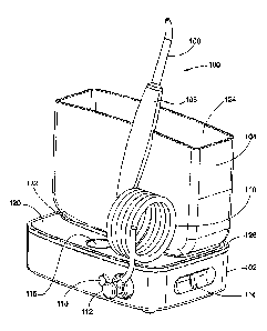
reservoir
cavity.
[0007] In another implementation, a handle for an oral irrigator for
directing a focused
stream of fluid has a housing defining a slot formed in an outer wall of the
housing. The slot
may be bounded by two opposing walls spaced apart from each other and a
transverse wall
at a terminal interior end of the opposing walls such that the outer wall of
the housing is open
to the slot at lateral sides of the two opposing walls and at a base end of
the opposing walls
opposite the transverse wall. In some implementations, the opposing walls are
parallel to
each other. In other implementations, the two opposing walls are planar. In
some
implementations, the opposing walls are both planar and parallel to each
other. In further
implementations, the handle may extend from a first end to a second end in a
generally
elongate form along a longitudinal axis and the opposing walls defining the
slot extend at an
angle with respect to the longitudinal axis.
[0008] In another implementation, an oral irrigator may include a
removable reservoir
defining a reservoir cavity, a base unit housing a motor and a pump, and a
power assembly
in selective communication with the motor. In a first configuration the
reservoir is coupled to
a top surface of the base unit, the reservoir cavity is fluidly coupled to the
pump, and the
power assembly is electrically connected to the motor. In a second
configuration, the base
unit is fluidly decoupled from the reservoir cavity, the base unit is
positioned within the
reservoir cavity, and the power assembly is electrically disconnected from the
motor and is
received within a cavity defined in the base unit. In further implementations,
the base unit
may include a base magnetic material. The power assembly may similarly include
a
retaining magnetic material. The base magnetic material and the retaining
magnetic
material may be aligned opposite to each other when the oral irrigator is in
the second
configuration and attract each other to thereby secure the power assembly
within the base
unit.
2
Date recue/Date received 2023-03-27
[0009] In a further implementation, an oral irrigator may include a base
unit, a removable
reservoir, and a belt drive assembly. The base unit may house a motor and a
pump. The
removable reservoir may define a reservoir cavity configured to mechanically
couple to a top
surface of the base unit and fluidly couple the reservoir cavity to the pump.
The belt drive
assembly may connect the motor to the pump. The belt drive assembly may
further include
a drive pulley connected to an output shaft of the motor, a driven pulley
spaced apart from
the drive pulley and mechanically connected to a piston that drives the pump,
and a
continuous belt connecting the drive pulley to the driven pulley. In a further
implementation,
a tensioning structure may exert a tension force on the belt. In yet a further
implementation,
the tensioning structure may include an idler pulley and a tension member. The
idler pulley
may be positioned between and pivotably mounted with respect to the drive
pulley and the
driven pulley and positioned in contact with the belt. The tension member
connected to the
idler pulley and configured to pull the idler pulley about a pivot to maintain
a contact force
with the belt. In a further implementation, the base unit may include a
chassis to which each
of the motor, the driven pulley, and the idler pulley are attached. A bracket
may be pivotably
attached to the chassis. The idler pulley may be rotationally attached to the
bracket. The
tension member may be connected to the bracket at a first end and connected to
the chassis
at a second end. IN an additional implementation, the tension member is a
torsion spring,
the bracket is L-shaped, the idler pulley is attached to a first terminal end
of the L-shaped
bracket, and a first end of the torsion spring is attached to a second
terminal end of the L-
shaped bracket. A center axis of the torsion spring may be aligned with a
pivot point of the
L-shaped bracket.
[0010] In another implementation, an oral irrigator may include a base
unit and a
removable reservoir. The a base unit may be encased by a housing covering a
motor and
drive system positioned in a first, dry compartment formed in the base unit
housing and a
pump positioned in a second, wet compartment formed in the base unit housing.
The
removable reservoir may define a reservoir cavity configured to mechanically
couple to a top
surface of the base unit and fluidly couple the reservoir cavity to the pump.
A piston may be
connected at a first end to the drive system and connected at a second end to
the pump. A
diaphragm seal may be positioned between the dry compartment and the wet
compartment
through which the piston passes, The diaphragm seal may further include a
frame, two
elastomeric bead seals, and an elastomeric bellows. The frame may be made of a
rigid
material, define a center aperture, and have a dry face oriented toward the
dry compartment
and a wet face oriented toward the wet compartment. A first elastomeric bead
seal may be
formed at least partially along and adjacent to at least a portion of a
perimeter edge of the
dry face. A second elastomeric bead seal may be formed at least partially
along and
adjacent to at least a portion of a perimeter edge of the wet face. The
elastomeric bellows
3
Date recue/Date received 2023-03-27
may seal against and extend across the center aperture. The bellows may
further define a
center opening configured to receive and seal about a shaft portion of the
piston.
[0011] In a further implementation, an oral irrigator may include a base
unit, a removable
reservoir, a handle, a first poppet valve, and a second poppet valve. The base
unit may
house a motor and a pump. The removable reservoir may define a reservoir
cavity
configured to mechanically couple to a top surface of the base unit and
fluidly couple the
reservoir cavity to the pump. The handle may be removably connected to the
base unit and
fluidly coupled to the pump by a hose to direct fluid flow from the pump. The
first poppet
valve may be positioned in a removable connector attached at a first end to
the hose and
releasably attached at a second end to a port in the base unit in fluid
communication with the
pump. The first poppet valve may be configured to open in response to fluid
under pressure
received from the pump to allow fluid to flow through the hose to the handle.
The first
poppet valve may also be configured to close in the absence of fluid under
pressure
received from the pump. The second poppet valve may be positioned in the port
and
configured to open in response to connection with the connector and configured
to close
when the connector is removed from the port. In additional implementations, a
shuttle valve
may be positioned in the base unit in fluid communication with the pump at a
first end and
with the reservoir at a second end. The shuttle valve may be configured to
block a primary
fluid flow passage to the reservoir when the pump provides a positive pressure
stroke and
configured to open the primary fluid flow passage to the reservoir when the
pump provides a
negative pressure stroke. A third poppet valve may be housed in a valve cavity
defined
within the shuttle valve. The third poppet valve may be configured to block
fluid flow from
the reservoir through the valve cavity and configured to open and allow fluid
flow through the
valve cavity toward the reservoir when fluid pressure at the first end of the
shuttle valve
exceeds a threshold pressure.
[0012] This Summary is provided to introduce a selection of concepts in
a simplified
form that are further described below in the Detailed Description. This
Summary is not
intended to identify key features or essential features of the claimed subject
matter, nor is it
intended to be used to limit the scope of the claimed subject matter. A more
extensive
presentation of features, details, utilities, and advantages of the present
invention as defined
in the claims is provided in the following written description of various
embodiments of the
invention and illustrated in the accompanying drawings.
BRIEF DESCRIPTION OF THE DRAWINGS
[0013] Fig. 1A is a front isometric view of an oral irrigator.
[0014] Fig. 1B is a side elevation view of the oral irrigator of Fig.
1A.
[0015] Fig. 1C is a rear elevation view of the oral irrigator of Fig.
1A.
4
Date recue/Date received 2023-03-27
[0016] Fig. 1D is a bottom plan view of the oral irrigator of Fig. 1A.
[0017] Fig. 2 is a front elevation view of a reservoir for the oral
irrigator.
[0018] Fig. 3A is a front isometric view of a base for the oral
irrigator.
[0019] Fig. 3B is a top plan view of the base of Fig. 3A.
[0020] Fig. 3C is a front isometric view of the base of Fig. 3A.
[0021] Fig. 3D is a top plan view of the base of Fig. 3A.
[0022] Fig. 4 is an exploded view of the base of Fig. 3A.
[0023] Fig. 5 is a top plan view of a lower housing for the base.
[0024] Fig. 6A is a front elevation view of operating components for the
oral irrigator as
arranged in the base.
[0025] Fig. 6B is a top plan view of the operating components of Fig. 6A
illustrating their
layout in the base.
[0026] Fig. 6C is a cross-sectional view of the oral irrigator taken
along line 60-6C in
Fig. 1C.
[0027] Fig. 6D is a side elevation view of the operating components of
Fig. 6A.
[0028] Fig. 7A is a front isometric view of a drive assembly for the
oral irrigator.
[0029] Fig. 7B is an exploded view of the drive assembly.
[0030] Fig. 8A is first side elevation view of a driven pulley for the
drive assembly.
[0031] Fig. 8B is a side isometric view of the driven pulley for the
drive assembly.
[0032] Fig. 9A is a top plan view of a connecting rod for the drive
assembly.
[0033] Fig. 9B is a side elevation view of the connecting rod.
[0034] Fig. 10 is an enlarged view of the cross-sectional view of Fig.
6C.
[0035] Fig. 11A is a front isometric view of a pump housing for a pump
assembly.
[0036] Fig. 113 is a rear isometric view of the pump housing of Fig.
11A.
[0037] Fig. 12A is a front isometric view of a regulator housing for a
pressure assembly.
[0038] Fig. 123 is a cross-sectional view of the regulator housing taken
along line 12B-
12B of Fig. 12A.
[0039] Fig. 13 is an exploded view of a pressure regulator valve.
[0040] Fig. 14 is an exploded view of a connection assembly.
[0041] Fig. 15A is a rear isometric view of the oral irrigator of Fig.
1A with the power
assembly in a use orientation.
[0042] Fig. 15B is front isometric view of the oral irrigator of Fig.
15A.
[0043] Fig. 16 is a front isometric view of the oral irrigator of Fig.
lA in a storage or
collapsed position.
[0044] Fig. 17 is a rear isometric view of an alternate embodiment of an
oral irrigator.
[0045] Fig. 18 is a cross-sectional view of the oral irrigator taken
along line 18-18 of
Fig. 17.
Date recue/Date received 2023-03-27
[0046] Fig. 19A is an exploded top isometric view of a power button
assembly of the oral
irrigator of Fig. 17.
[0047] Fig. 1913 is an exploded bottom isometric view of a power button
assembly of the
oral irrigator of Fig. 17.
[0048] Fig. 20 is a front isometric view of a connecting rod of the oral
irrigator of Fig. 17.
[0049] Fig. 21 is a front isometric view of a driven pulley of the oral
irrigator of Fig. 17.
[0050] Fig. 22A is an isometric view of an alternate embodiment of a
drive assembly.
[0051] Fig. 223 is a front elevation view of the drive assembly of Fig.
22A.
[0052] Fig. 23A is a front isometric view of an alternate embodiment of
a hose latch
assembly.
[0053] Fig. 233 is rear isometric view of the hose latch assembly of
Fig. 23A
[0054] Fig. 24 is an isometric view of an alternate embodiment of an
eject button.
[0055] Fig. 25 is a right side elevation view of the handle of the oral
irrigator of Fig. 1.
[0056] Fig. 26 is a right side isometric view of a diaphragm seal of the
oral irrigator of
Fig. 17.
[0057] Fig. 27 is a left side isometric view of the diaphragm seal of
Fig. 26.
[0058] Fig. 28 is an isometric view of an actuator with a rack gear from
the oral irrigator
of Fig. 17.
[0059] Fig. 29 is an isometric view of a gear assembly attached to the
pump assembly
which interfaces with the rack gear of Fig. 28,
[0060] Fig. 30 is a front isometric view in cross section of the
actuator of Fig. 28
interfacing with the gear assembly of Fig. 29.
DETAILED DESCRIPTION
[0061] An example of the present disclosure includes an oral irrigator
having a reduced
form factor as compared to conventional countertop oral irrigators. The oral
irrigator
includes a base, a removable reservoir, a power assembly, a drive assembly, a
handle, and
a pump assembly. In one embodiment the reservoir and power assembly are each
reconfigurable from a storage or collapsed position to a use or expanded
position. For
example, the reservoir can transition from being seated on a top surface of
the base in the
use position to the storage position where it is disconnected from the base
unit and the base
unit is inserted into the reservoir cavity for storage. Similarly, the power
assembly stores
within a compartment in the base but is removed from the base and connected to
an
electrical source, such as a power outlet, for use. The handle can also be
selectively
connected with and disconnected from the base and reservoir to allow the
handle to be
removed and stored when desired. Countertop irrigators use regular outlets
(100-240V
outlets) and are therefore more powerful and potentially more desirable to a
user than
6
Date recue/Date received 2023-03-27
handheld units, which typically use a 2.4V battery pack. In addition,
countertop irrigators are
ready for use at anytime as long as an outlet is available. In contrast,
handheld irrigators
must be charged before they can be used. For travel, a user may forget to
charge the unit
before departure and the unit may not be operational when the user arrives at
his destination
[0062] The oral irrigator may also include a drive assembly having
reduced noise as
compared to conventional oral irrigators. The drive assembly includes a pinion
pulley driven
by a motor, a driven pulley indirectly driven by a pinion pulley, and a belt
connected to the
pinion pulley and the driven pulley to transfer motion from the pinion pulley
to the driven
pulley. The belt seats on the outer surface of the two pulleys and reduces
noise generated
by the drive assembly as the pulleys, unlike gears, do not physically mesh
with one another
in order to transfer motion therebetween. The drive assembly may also include
a tension
assembly to insure that the belt drive tension remains at an appropriate level
based upon the
load on the motor.
[0063] The driven pulley is connected to a connecting rod that drives a
piston to pump
fluid between a reservoir and a handle. In one embodiment, the connecting rod
includes a
bend or elbow extension. The bend allows a seal structure to seat around and
seal against
the connecting rod.
[0064] The oral irrigator includes a number of different valves for
preventing fluid
leakage in the storage and use configurations. For example, the base and the
handle each
include connectors for sealing inlets and outlets when the handle and base are
disconnected
from one another. These connectors prevent the hose connected to the handle
and the
aperture in the base for receiving the hose from leaking fluid when the oral
irrigator is not in
use.
OVERVIEW OF THE ORAL IRRIGATOR
[0065] With reference now to the figures, the oral irrigator of the
present disclosure will
be discussed in more detail. Figs. 1A-1D illustrate various views of an oral
irrigator. With
reference to Figs. 1A-1D, the oral irrigator 100 includes a base 102, a
reservoir 104, a
handle 106 connected to a tip 108, and a hose 110 fluidly connecting the
handle 106 to the
base 102. The oral irrigator 100 also includes a power assembly 134 removably
connected
to the base 102 and configured to electrically connect to the base 102 to
provide power to
various components within the oral irrigator 100. The reservoir 104, handle
106, and
hose 110 are removably connected to the base 102, allowing the oral irrigator
100 to be
collapsed to a storage configuration and inserted into a travel carry bag or
other container for
storage or transport.
[0066] The base 102 houses a motor, a pump assembly, a pressure
assembly, and
various connectors to fluidly connect the handle 106 to the reservoir 104 and
to pull fluid
7
Date recue/Date received 2023-03-27
from the reservoir 104 and expel it from the outlet of the tip 108. Each of
the various
components of the oral irrigator 1 00 will be discussed in detail below.
Reservoir
[0067] The reservoir 104 stores fluid, such as water, mouthwash, etc.,
for use with the
oral irrigator 100. Fig. 2 is a front elevation view of the reservoir 104. The
reservoir 104 is
generally rectangular in shape and includes a front wall 152, rear wall 154,
bottom wall 140,
and two sidewalls 144, 144. The top end of the reservoir 104 is open and each
of the front,
rear, and side walls include a top edge 128, 129, 148, 150 at the top end of
the
reservoir 104. In one embodiment, the top edges 128, 129 of the front and rear
walls 152, 154 vary in height along their length and curve upward toward a
center of the
reservoir 1 04. In other words, the front and rear walls 152, 154 have an
increased height
toward the center as compared to the edges. In this manner, the top end of the
reservoir 104 bows or arcs upward in the middle and downward toward each of
the
sidewalls 144, 146.
[0068] Each of the walls is interconnected to define a reservoir
compartment 124 for
holding fluid. In some embodiments, the edges interconnecting the front wall
152, rear
wall 154, bottom wall 140, and sidewalls 144, 146 are curved to define a soft
angle, rather
than a right angle that would define a sharp edge. This curvature is not only
aesthetically
pleasing, but also allows the reservoir 104 and the oral irrigator 100 to
slide into and out of a
packaging or container as the edges will not snag on the material and also
will distribute
impact forces more evenly across the reservoir 104.
[0069] The reservoir compartment 124 is dimensioned and shaped not only
to hold a
desired amount of fluid, but also to correspond to the shape and dimensions of
the base
unit 102. In particular, the reservoir compartment 124 is shaped such that the
base unit 102
can fit easily within the reservoir compartment 124. A reservoir port 142
extends downward
from the bottom wall 140 and is fluidly connected to the reservoir compartment
124 via an
aperture defined through the bottom wall 140.
Base
[0070] The base 102 supports the reservoir 104 and encloses the pumping
and
operating assemblies of the oral irrigator 100. Figs. 3A-3D illustrate various
views of the
base 102 with the reservoir and the power assembly hidden. Fig. 3D differs
from Fig. 3B in
that a portion of the hose connector 112 is shown. Fig. 4 is an exploded view
of the base.
Fig. 5 is a top plan view of a lower housing of the base 102. With reference
to Figs. 3A-4,
the base 102 includes a lower housing 178, an upper housing 180, a face plate
182, and a
trim ring 126, each of which interconnect together.
8
Date recue/Date received 2023-03-27
[0071] The trim ring 126 is an accent ring of material and includes a
button ring 186
connected thereto. In many embodiments the trim ring 126 is a different
material from the
other components of the base unit to provide an aesthetically pleasing
appearance. The trim
ring 126 helps to secure the various base components together and may include
ribs,
flanges, and other fastening elements to press fit or otherwise connect to the
other
components.
[0072] With reference to Fig. 4, the face plate 182 defines the top
surface 120 of the
base 102 and assists in enclosing the interior compartments of the base 102.
The face
plate 182 may include cutouts, such as the upper housing aperture 188 and
button
aperture 190 for exposing select components of the oral irrigator 100, but may
be differently
configured as desired. In some embodiments, the face plate 182 may be a
transparent
material, such as transparent plastic, and include a paint or coating on the
interior surface
thereof. As the painted color is beneath the top outer surface, the outer
surface of the
transparent face plate 182 has a high gloss appearance. Additionally because
the painted
color is below the outer surface it will be less exposed to environmental wear
and tear and
thus last longer and be less likely to chip.
[0073] The upper housing 180 forms the sealing surface to substantially
enclose the
internal compartment of the lower housing 178, The upper housing 180 may also
define a
support surface for the reservoir 104 when the reservoir 104 is seated on top
of the
base 102. For example, the upper housing 180 may include an engagement surface
122
having a concave shape that bows downward toward the center and raises upward
toward
the sidewalls of the upper housing 180. A lip 196 may surround the perimeter
of the
engagement surface 122 and help to align the reservoir 104 with respect to the
engagement
surface 122, as well as prevent fluids from exiting the engagement surface 122
(such as
those that leak from the reservoir 104 or down the sides of the reservoir).
[0074] The upper housing 180 may also include a sealing wall 192 and a
port wall 194
extending downward from a bottom surface. The sealing wall 192 may be a
substantially
planar member positioned toward the front middle end of the upper housing 180.
The port
wall 194 may be a generally cylindrically shaped wall positioned near the rear
end of the
upper housing 180 and configured to receive elements for connecting the
reservoir 104 to
the base 102, such as valves and connectors.
[0075] With reference to Figs. 3A- 3D, and 5, the lower housing 178 of
the base unit 102
includes a front wall 164, a back wall 170, two sidewalls 166, 168, and a
bottom wall 202.
The combination of the walls 164, 166, 168, 170, 202 defines a base cavity 196
in which the
pump assembly, pressure assembly, drive assembly, and other components are
received
and as such may be varied to accommodate those components as desired. In one
embodiment, the lower housing 178 includes a power block cavity 174 defined in
the back
9
Date recue/Date received 2023-03-27
wall 170 (see Fig. 3C). The power block cavity 174 is configured to receive
the power
assembly 134, which can be removed from the lower housing 178 as discussed
below. In
these embodiments, the lower housing 178 may include alignment and securing
features,
such as alignment ribs 176 extending along a length of the walls defining the
power block
cavity 174. The alignment ribs 176 are configured to engage corresponding
grooves on the
power assembly 134.
[0076] With reference to Figs. 4 and 5, the lower housing 178 may also
include a
groove 198 defined on the upper surface of the bottom wall 202. A contoured
sealing
wall 200 extends upward from the bottom wall 202 and is configured to
correspond to a
shape of the reservoir valve connector and pressure actuator. The sealing wall
200 and the
groove 198 are sealing components that assist in defining dry compartments
204, 208 and a
wet compartment 206. The dry compartments 204, 208 are sealed from the
external
environment, as well as the components that are fluidly connected to the
reservoir 104 to
reduce damage to components stored therein.
[0077] With reference to Figs. 3A and 4, the lower housing 178 also
includes a hose
aperture 160, a button aperture 162, a slide recess 184, and a power connector
aperture 210 for connecting elements to the base unit 102. The hose aperture
160 and the
button aperture 162 are both defined through the front wall 164 and extend
into the wet
compartment 206. Similarly, the slide recess 184 defines a recessed track on
sidewall 166
and includes openings 212 (see Fig. 3A) for connecting an actuator to
components stored
within the lower housing 178. The power connector aperture 210 is defined
through the
back wall 170 and extends into the dry compartment 204.
[0078] Additionally, with reference to Fig. 5, in some embodiments, the
lower
housing 178 includes a pocket 476 defined in the back wall 170 in the power
block
cavity 174. The pocket 476 is defined in the internal compartment of the lower
housing 178
and is configured to receive a magnet 474. As will be discussed in more detail
below, the
magnet 474 is configured to interact with the power assembly to secure it in
position.
OPERATING COMPONENTS
[0079] The operating components of the oral irrigator 100 will now be
discussed in more
detail. Figs. 6A and 6B illustrate various views of the main operating
components of the oral
irrigator with the various housings removed to better illustrate the internal
components. As
shown in Figs. 6A and 6B, the oral irrigator 100 may include a drive assembly
216, a pump
assembly 214, a pressure assembly 228, and a connection assembly 230, each of
which will
be discussed, in turn, below. Each of the assemblies may be interconnected
together and
received within respective compartments within the lower housing 178.
Date recue/Date received 2023-03-27
Mechanical Power Transmission Assembly
[0080] The drive assembly 216 converts rotational movement from a motor
into
translational mechanical movement that drives the pump assembly 214. Fig. 7A
illustrates a
front isometric view of the drive assembly 216. Fig. 7B illustrates an
exploded view of the
drive assembly 216. The drive assembly 216 includes a motor 218, a pinion
pulley 240, a
driven pulley 250, a belt 238, a ball bearing race 252 having inner and outer
rings
encompassing a ball bearing ring 244, belt securing flanges 231, 248, a gear
pin 232, and a
connecting rod 236. The motor 218 includes a drive shaft 242 and, as shown in
Fig. 6B, is
electrically connected to the male power connector socket 136 forming a power
inlet of the
base 102 via wires 254.
[0081] The motor 218 may be substantially any type of device that
converts electricity
into motion. In one embodiment, the motor 218 includes a signal conditioner
such as a
varistor.
[0082] The pinion pulley 240 is received around or otherwise secured to
the drive
shaft 242 such that the pinion pulley 240 rotates with the drive shaft 242.
The pinion
pulley 240 optionally may include a plurality of teeth 256 or grip elements
for enhancing a
frictional engagement with the belt 238. However, depending on the
configuration of the
belt 238, the pinion pulley may not include teeth or may include other
engagement features.
[0083] Figs. 8A and 8B illustrate various views of the driven pulley
250. The driven
pulley 250 is driven by the pinion pulley 240 via the belt 238. The driven
pulley 250 may be
a relatively cylindrically shaped disc having a first surface or side 258 and
a second surface
or side 266. In one embodiment, the driven pulley 250 includes a plurality of
teeth 270 or
other engagement elements that extend radially outward from the second surface
266 and
are oriented to face outward away from a center of the pulley 250. A pin
aperture 268 is
defined through the driven pulley 250 and extends between the first and second
surfaces 258, 266.
[0084] With reference to Fig. 8B, the driven pulley 250 also includes an
engagement
boss 260 that extends outward from the first surface 258. The engagement boss
260 may
be formed as a cylindrical protrusion and may include one or more ribs 264
extending
lengthwise on an outer surface thereof. In many embodiments, the engagement
boss 260 is
offset from a center axis of the driven pulley 250. The bearing race 252 (see
Fig. 7B) may
seat around the engagement boss 260 and is held in place by the ribs 264. For
example,
the pin aperture 268 is typically aligned with the center axis of the driven
pulley 250 and the
engagement boss 260 is offset relative thereto to form an eccentric post. As
the
engagement boss 260 extends away from the first surface 258, in some
embodiments, a pin
structure 262 may be arranged within the engagement boss 260 to increase the
length of the
pin aperture 268, extending it through the height of the engagement boss 260.
In some
11
Date recue/Date received 2023-03-27
embodiments, the pin structure 262 may be longer than the height of the
engagement
boss 260.
[0085] With continued reference to Fig. 8B, the driven pulley 250 may
also include a
lip 257 or edge that defines a perimeter of the first surface 258. The lip 257
may extend
outward and upward from the first surface 258 such that the first surface 258
is partially
recessed below the edge 257.
[0086] With reference again to Fig. 7B, the flanges 230, 248 are used
for securing the
belt 238 to the pulleys 240, 250 and as such may be configured to mate with
and connect to
the respective pulley. In some examples, the flanges 230, 248 may be secured
to the
pulleys 240, 250 using various attachment methods, such as ultrasonic welding,
adhesive,
riveting, etc. In some examples, the flanges 230, 248 may be integrated into
each of the
pulleys 240, 250.
[0087] The belt 238 transmits rotation from the pinion pulley 240 to the
driven
pulley 250. The belt 238 may include a plurality of teeth for engaging the
pinion pulley 240
and the driven pulley 250. In one embodiment, the belt 238 is an MXL-type
timing belt with a
pitch of 0.08" and a 3/16" width. However, many other types of belts with
different pitch
length and widths may be used, such asadditional synchronous belts with other
timing
profiles such as XL and L, or HTD type with pitches such as 3mm, 5mm, or 8mm,
GT type
with pitches such as 2mm, 3mm, 5mm, 8mm pitches, chevron style synchronous
belts;
round belts; flat belts; elastic belts; and V-shaped belts.
[0088] Fig. 9A is a top plan view of the connecting rod 236. Fig. 9B is
a side elevation
view of the connecting rod 236. As shown in Figs. 9A and 9B, the connecting
rod 236
includes a connecting end 272 defining a cylindrical ring having a plurality
of tabs 285
extending inward from an interior surface. The connecting end 272 is shaped
and
dimensioned to be received around the bearing race 252 and thereby around the
engagement boss 260 of the driven pulley 250. The tabs 285 secure the
connecting
end 272 to the outer surface of the bearing race 252 (see Fig. 7B) thereby
allowing the
engagement boss 260 to rotate within the cylindrical ring of the connecting
end 272. An
arm 274 extends from the connecting end 272. The arm 274 is generally
straight, but
includes an angled bend 276 or elbow in a middle portion thereof. The angled
bend 276
assists in allowing the drive assembly 216 to fit within the lower housing and
maintain the
reduced form factor of the oral irrigator 100. Additionally, the bend allows
the connecting
rod 236 to pass through and center on a seal between wet and dry compartments.
From the
angled bend 276, the arm 274 transitions to a terminal end 278 having a ball
280.
[0089] As shown in Fig. 10, the drive assembly 216 also includes a
diaphragm seal 480
having a seal top surface 484 and a rod aperture through a center thereof. The
seal top
surface 484 extends radially outward from the rod aperture and then downward
at an angle
12
Date recue/Date received 2023-03-27
to define a flexible skirt 486. The skirt 486 may be conical or frustum shaped
and define a
bellows. The skirt 486 is flexible and configured to resiliently deform and
return to its original
shape. A crease at the bottom of the skirt 486 varies as the seal is deformed.
A beaded
flange 482 extends radially outward from a top end of the crease. The flange
482 includes a
flat top surface and a convexly curved bottom surface.
Pump Assembly
[0090] With reference to Fig. 10, which is an enlarged view of Fig. 6C,
the pump
assembly 214 includes a piston 283 that is driven by the drive assembly 216
and a pump
body 284. The piston 283 is generally cylindrical and has on its top surface
an annular
flange 318 and an interior pedestal 320. An annular valley is defined between
the annular
flange 318 and interior pedestal 320. A curved interior surface 321 on the
interior of the
piston is configured to receiving the ball 280 of the connecting rod 236 in
order to form a ball
joint.
[0091] Figs. 11A and 11B illustrate front and rear isometric views of
the pump body 284.
The pump body 284 includes a pump wall 288 defining a pump chamber 322
therein. A
securing bracket 294 is connected to a side surface of the pump wall 288 and
is configured
to receive a fastening element. Additionally, a spring wall or post 292
extends from the
same side surface as the securing bracket 294 for receiving components of the
eject button,
discussed in more detail below. A hose interface 296 is connected to a first
end of the pump
wall 288 and includes a plate 310 having first and second sides with
corresponding
connection features for coupling the pump body 284 to internal and external
valves.
[0092] In particular, with reference to Fig. 11A, a valve housing 300
for interfacing with
the hose connector 112 extends from a first side of the plate 310. The valve
housing 300
may be shaped as a cylindrical wall and include a ledge 302 extending
concentrically within
the valve housing 300 from the plate 310. The ledge 302 may be shorter than
the valve
housing 300 and terminate before an outer edge of the valve housing 300. The
back
wall 304 of the valve housing 300, which may form a portion of the first side
of the plate 310,
includes a pin recess 306 and a pump outlet 308. The pump outlet 308 is
fluidly connected
to the pump chamber 322.
[0093] With reference to Fig. 11B, the rear side of the plate 310
includes a tube 312 for
interfacing with the pressure assembly 228 and corresponding valves. The tube
312 may
include one or more prongs 314 extending from an interior surface thereof to
engage with
corresponding valve elements. A pump inlet 316 is defined as an aperture
through the
tube 312 and is fluidly connected to the tube 312 and the interior of the pump
chamber 322.
13
Date recue/Date received 2023-03-27
Pressure Assembly
[0094] With reference again to Figs. 6A and 6C, the pressure assembly
228 will now be
discussed in more detail. The pressure assembly 228 allows a user to
selectively adjust the
pressure output by the oral irrigator 100. In one embodiment, the pressure
assembly 228
includes a regulator housing 326, a dual valve assembly 328, and a pressure
valve 344.
[0095] Figs. 12A and 12B illustrate an isometric view and a cross-
sectional view,
respectively, of the regulator housing 326. With reference to Figs. 12A and
12B, the
regulator housing 326 defines a body for receiving the pressure valve 344 and
the dual valve
assembly 328. Additionally, the regulator housing 326 defines a fluid flow
path from the
reservoir 104 to the pump assembly 214 and so, in some embodiments, may also
form a
part of the pump housing.
[0096] The regulator housing 326 includes a main body 354 that may have
a generally
cylindrical shape defining a main channel 362 therethrough. An inlet 356 is
fluidly connected
to the main channel 362 and extends from a first end of the main body 354. A
regulator
outlet 364 is defined on the opposite end of the main channel 362. A valve
compartment 350 is defined on a side of the main body 354 and includes a
cavity for
receiving the pressure valve 344, two securing features 352a, 352b connected
to either side
of the compartment 350, a valve inlet 358 and a valve outlet 360. The valve
inlet 358 is
fluidly connected to the main channel 362 and the valve outlet 360 is fluidly
connected to the
housing inlet 356. In other words, fluid flows through the valve compartment
350 in the
opposite direction it flows in the main channel 362 to in a sense siphon fluid
headed to the
pump assembly 214 and direct it back to the reservoir 104. The regulator
housing 326 may
include a plurality of securing features, such as brackets 366, 368 that are
configured to
receive fasteners for securing the housing within the base 102.
[0097] Fig. 13 illustrates an exploded view of the pressure valve 344,
the biasing
element 348, and the seal 340. With reference to Figs. 6C and 13, the pressure
valve 344 is
used to vary one or more characteristics of the flow channel between the inlet
and
outlet 360, 358 in the regulator housing 326. With reference to Figs. 6C, 6D,
and 13, the
pressure valve 344 includes a gear face 370 for interfacing with and
connecting to the
gear 334 and a sealing face 374. The sealing face 374 varies in the thickness
and includes
a flow channel 376 defined therein. The flow channel 376 varies in dimension
and shape
and extends in a generally curved manner around a central area of the sealing
face 374.
[0098] The seal 340 is biased against the sealing face 374 of the
pressure valve 344
and includes a flow aperture 378 defined therethrough. The flow aperture 378
is typically in
fluid communication with the flow channel 376 of the sealing face 374 and the
main
channel 362 but varies where it engages with the flow channel 376 based on the
position of
the pressure valve 344, as discussed in more detail below.
14
Date recue/Date received 2023-03-27
[0099] With reference to Figs. 6C and 6D, the pressure assembly 228
includes the
gear 334, a corresponding rack 380, and the actuator 114. The rack 380
includes a plurality
of teeth 382 that engage with the teeth 384 on the gear 334. The actuator 114
is coupled to
the rack 380, which moves laterally relative to the rack bracket 336. For
example, the rack
bracket 336 may include one or more longitudinal grooves and the rack 380 may
include
pegs that are received into the grooves to secure the rack 380 to the bracket
336. The
grooves allow the rack 380 to slide laterally relative to the bracket 336. The
actuator 114 is
connected to the rack 380 and configured to move the rack 380 in the lateral
direction to
actuate the gear 334, as discussed in more detail below.
[00100] With reference to Fig. 10, the dual valve assembly 328 will now
be discussed in
more detail. The dual valve assembly 328 acts both as a regulator valve to
regulate fluid
into and out of the reservoir into the pump chamber 322, as well as to help
prevent damage
to the pump in the event of a blockage at the tip, such as activation of a
pause button on the
handle 106, such that the dual valve acts as a check valve. For the primary
valve function of
the dual valve assembly 328, the dual valve assembly 328 includes a valve
housing 388
which may be a substantially cylindrical hollow component and is configured to
slide within
the main channel 362. The valve housing 388 terminates in a terminal end 394
having an
aperture defined through a front surface thereof. The second end of the valve
housing 388
includes a seal cap 398 that includes a flow channel 400 defined therethrough.
The flow
channel 400 is in communication with the reservoir connector 330.
[00101] For the secondary or check valve function, the dual valve
assembly 328 includes
a spring actuated valve within the valve housing 388. In particular, a support
post 396
having a flow channel defined therethrough is connected to the seal cap 398, a
biasing
element 392 is received within the valve housing 388 and aligned with the
support post 396.
A plunger 390 is connected to the biasing element 392 and configured to move
therewith.
The plunger 390 may include a tapered shape, such as a cone or frustum, and
has a
terminal end diameter that is the same diameter as that of the aperture in the
terminal end
394 of the valve housing 388. The force of the biasing element 392 is selected
to be
overcome by fluid back pressure that exceeds a predetermined amount, such as
the
pressure build up due to a blockage of the jet tip 108.
Handle Connection Assembly
[00102] The connection assembly 230 will now be discussed in more detail. Fig.
14
illustrates an exploded view of the connection assembly 230. With reference to
Figs. 6C
and 14, the connection assembly 230 includes an outlet fitting 402, a spring
bearing 406, a
biasing element 408, a poppet 410, a poppet cap 412, a top cap 416, and
sealing
members 404, 414. The outlet fitting 402 interfaces with the pump body 284 and
includes a
Date recue/Date received 2023-03-27
central boss 418 having a cavity 420 defined therethrough. The outlet fitting
402 may
include one or more securing flanges 422a, 422b for receiving fasteners to
secure to the
pump body, portions of the housing, etc.
[00103] The bearing 406 includes a support post 424 (see Figs. 6C and 10)
extending
from a rear surface and a receiving post 426 extending from a front surface.
The
posts 424, 426 are configured to be positioned within a receiving recess in
the pump
body 284 and receive the biasing member 408, respectively.
[00104] As shown in Fig. 14, the poppet 410 is a generally cylindrical
body having a
tapered end with a closed tip 428, One or more fluid apertures 430 may be
defined by the
sidewalls of the body. The end cap 412 is configured to seat on the closed tip
428 of the
poppet 410 and may be configured to correspond to the shape and dimension of
the closed
tip 428 such that it may be press fit onto the closed tip 428 end of the
poppet 410.
[00105] The top cap 416 forms the end component of the connection assembly 230
and
is connected to the outlet fitting 402 with the various components of the
connection
assembly 230 positioned between the two. The sealing components may be 0-
rings, such
as seal element 404, or seal-cups, such as seal member 414 and may be
positioned around
select components of the connection assembly 230 or as desired to create fluid-
proof
connections.
[00106] The latch assembly 432 selectively connects and disconnects the hose
connector 112 to the base 102 will now be discussed in more detail. With
reference to
Figs. GA, 60, and 10, the latch assembly 432 includes the eject button 118, a
biasing
element 444, and a latch 434. The eject button 118 is configured to actuate
the latch 434
and includes an outer surface that a user actuates, a central cavity 446 for
receiving the
biasing element 444 and a tapered interior actuation tip 442. The actuation
tip 442 is
shaped as a frustum or blunt ended cone that slowly increases in diameter from
the most
interior surface toward the outer surfaces. As will be discussed in more
detail, the actuation
tip 442 is configured to move the latch 434 from an engaged position to a
released position.
The latch 434 includes two latch arms 436a, 436b connected together at one end
by a leaf
spring 440. Each of the latch arms 436a, 436b are generally elongated members
and
include detents 438a, 438b extending inward from a first sidewall toward the
opposite arm.
[00107] The hose connector 112 is used to fluidly connect the handle 106
to the
base 102 and will now be discussed in more detail. With reference to Figs. 3D
and 10, the
hose connector 112 includes a connector body 452 with a cap 450 connected
thereto. The
connector body 452 defines an interior lumen 456 housing a spring actuated
valve and a
lower body 462 that is partially inserted to the base 102, as discussed in
more detail below.
The interior lumen 456 of the connector body 452 is fluidly connected to a
prong lumen 466
that is defined by a prong 464 extending downward from a bottom end of the
connector
16
Date recue/Date received 2023-03-27
body 452. The prong 464 is positioned within a central region of the lower
body 462 and
includes one or more fluid apertures 468 defined as cutouts in its bottom end
for fully
connecting the prong lumen 466 to the pump assembly 214. The bottom end of the
lower
body 462 includes an external flange 470 extending circumferentially around
the lower
body 462. The external flange 470 selectively engages the latch 434 to secure
the hose
connector 112 to the base 102.
[00108] With reference to Figs. 3D and 10, the hose connector 112 includes a
leak valve
in the form of a poppet 460 and a biasing element 458. The biasing element 458
is secured
to a post extending from a bottom surface of the cap 450 and biases the poppet
460 toward
the entrance to the prong lumen 466. The poppet 460 is selected to have a
diameter that is
larger than the entrance to the lumen 466 such that when activated the poppet
460 seals the
entrance and prevents fluid, such as water stuck in the hose 110 after use of
the irrigator,
from leaking out when the hose connector 112 is removed from the base.
However, the
biasing element 458 is selected such that its force is able to be easily
overcome by the fluid
pressure expelled by the pump assembly 214.
ASSEMBLY OF THE ORAL IRRIGATOR
[00109] The assembly of the oral irrigator 100 will now be discussed. It
should be noted
that the below discussion is not meant to convey a particular assembly order,
but merely to
describe the connection of different elements to one another. As such, the
below discussion
is meant as illustrative only. With reference to Figs. 5, 6B, 6C, 7A, and 7B,
the drive
assembly 216 is connected together and secured to the lower housing 178 of the
base 102.
The chassis 220 and the motor 218 are connected together and secured in the
dry
compartment 208 of the lower housing 178.
[00110] The pinion pulley 240 is positioned on the drive shaft 242 of the
motor 218 and
the belt 238 is slid over the outer surface of the pinion pulley 240 with the
belt teeth meshing
with the teeth 256 on the outer surface of the pinion pulley 240. The flange
231 is then
connected to the outer perimeter of the pinion pulley 240 to secure the belt
on the outer
surface of the pinion pulley 240. The ball bearing race 252 is received around
the outer
surface of the engagement boss 260 of the driven pulley 250 and the connecting
end 272 of
the connecting rod 236 or crank is received around the outer surface of the
ball bearing race
252. The belt 238 is positioned on the outer surface of the driven pulley 250
and the
flange 248 is connected to the pulley 250 to secure the belt 238 on the
pulley. The belt 238
may alternatively be connected to the pulleys 240, 250 after the pulleys are
connected to
their driving components or respective shafts.
[00111] The gear pin 232 is then received through the aperture in the pin
structure 262 of
the driven pulley 250 and connected to a corresponding groove in the chassis
220. The
17
Date recue/Date received 2023-03-27
securing bracket 222 (see Fig. 7A) is then connected to the chassis 220 via a
plurality of
fasteners connected to bosses extended from the chassis 220, such as bosses
220a, 220b,
220c. With reference to Figs. 60 and 10, the connecting rod 236 is inserted
into an aperture
defined through the first sealing plate 488 and the top surface 484 of the
diaphragm seal 480
is positioned between the two sealing flanges 282a, 282b of the connecting rod
236. The
beaded flange 482 of the seal is clamped in position and the second sealing
plate 490 is
positioned over the edge of the diaphragm seal 480 and engages with the outer
surface of
the first sealing plate 488. The first and second sealing plates 488, 490 are
then clamped
together with fasteners, with the edges of the diaphragm seal being clamped
therebetween
and the connecting rod extending between apertures in the two plates 488, 490.
In this
configuration, the connecting rod 236 and the seal 480 create a fluid seal
between the dry
compartment 208 and the wet compartment 206 in the lower housing 178 of the
base 102.
[00112] The pump assembly 214 is connected and coupled to the drive assembly
216.
With reference Figs. 60 and 10, the piston 283 is connected to the ball 280 of
the
connecting rod 236. The pump body 284 is secured to the lower housing 178 of
the base
unit via fasteners connected to the securing bracket 294.
[00113] With reference to Figs. 10, 11A, and 14, the connection assembly 230
is
assembled and connected to the pump body 284. In particular, the support post
424 of the
bearing 406 is received within the pin recess 306 in the back wall 304 of the
valve
housing 300 in the pump body 284. The biasing element 408 is then positioned
around the
post 426 of the bearing 406. The poppet 410 is received around the biasing
element 408
with the cap 412 connected to the end portion of the poppet 410 with the
closed tip 428. The
outlet fitting 402 is positioned over the valve assembly such that the poppet
410 is positioned
within the boss 418. The 0-ring 404 is received between the fitting 402 and
the pump
body 284 and in one embodiment is held in position by the securing flanges
422a, 422b,
which are connected by fasteners to the securing posts 298a, 298b of the pump
body 284.
The seal member 414 may be a cup that is positioned within the top cap 416,
which is then
press fit or otherwise secured to the top end of the boss 418.
[00114] With reference to Figs. 10 and 11A, the eject button 118 and biasing
element 444
are connected to the pump body 284. In particular, the biasing element 444 is
received in
the spring wall or post 292 and the latch 434 is connected around the biasing
element 444
with the arms extending around the connection assembly 230. Then, the eject
button 118 is
connected to the biasing element 444 with the latch 434 positioned between the
eject
button 118 and the pump body 284. The biasing element 444 is received within
the central
cavity 446 of the eject button 118 with the actuation tip 442 being oriented
toward the pump
body 284.
18
Date recue/Date received 2023-03-27
[00115] The pressure assembly 228 is assembled and the dual or check valve
assembly 328 is received within the main channel 362 of the regulator housing
326. The
end portion of the dual valve assembly 328 is positioned within the tube 312
of the pump
body 284 and abuts against the prongs 314. The inlet 356 to the regulator
housing is
connected to the reservoir connector 330 and the regulator housing 326 is then
secured to
the lower housing 178 via the securing bracket 366, 368 and two fasteners. The
reservoir
connector 330 and the regulator housing 326 are positioned in the wet
compartment 206 of
the lower housing 178. The regulator housing 326 and the pump body 284 are
connected
together via fasteners securing the securing posts 298c, 298c of the pump body
284 and the
securing brackets 367 of the regulator housing 326 together.
[00116] With reference to Figs. 6C, 12A, 12B, and 13 the pressure valve
344 is
connected to the regulator housing 326. For example, the biasing element 348
is received
within the inlet 358 of the valve compartment 350 in the regulator housing 326
and the
seal 340 is received around the biasing element 348. An 0-ring 342 is
positioned in the
groove 372 in the valve 344 and the valve 344 is positioned in the valve
compartment 350
with the sealing face 374 positioned to face the back wall of the valve
compartment 350.
[00117] With reference to Figs. 6C and 60, the actuation assembly is then
connected to
the pressure valve 344. In particular, the rack bracket 336 is positioned
against the regulator
housing 326 aligned such that the fastening posts 352a, 352b align with
corresponding
features on the rack bracket 336. The rack bracket 336 is secured via
fasteners to the
regulator housing 326. The gear 334 is connected to the valve 344 by a
fastener, such as a
screw, and the rack 380 is press fit into the longitudinal slots in the rack
bracket 336. The
actuator 114 is then connected to the rack 380 and select teeth 382 are
positioned to
engage select teeth 384 of the gear 334.
Power Button
[00118] With reference to Figs. 6B and 6D, the power button 116 is secured on
a
bracket 431 and is electrically connected to the motor 218 through a circuit
board 131 that
electrically connects the motor 218 to a power source coupled to the power
port formed by
the male power connector socket 136 and the power assembly 134.
[00119] With reference to Figs. 6B and 6D, in the assembled positioned,
the drive
assembly 216, pump assembly 214, connection assembly 230, and pressure
assembly 228
are arranged in a U type shape when viewed from a top plan view. In this
manner, the
central region of the base 102 can be hollow to allow insertion of the power
assembly 134 in
the storage configuration or to define a battery compartment for receiving a
battery (or other
accessory storage). In one embodiment, the motor 218 is arranged so as to be
substantially
perpendicular to the pump body 284 and substantially parallel to the regulator
housing 326.
19
Date recue/Date received 2023-03-27
Further, the pump body 284 is arranged to be perpendicular to the reservoir
connector 330
and the reservoir outlet. These types of arrangements allow the oral irrigator
100 to have a
reduced size, both in width and height.
[00120] With reference to Fig. 4, once the internal components are
connected together
and received within the lower housing 178, the upper housing 180 is secured to
the lower
housing 178. The sealing wall 192 of the lower housing assists in sealing the
dry
compartment 208 from the wet compartment 206 in the lower housing 178. The
port
wall 194 of the upper housing 180 is positioned around a portion of the
reservoir
connector 330 to help prevent fluids from leaking from the reservoir connector
into the
secondary dry compartment 204. The upper housing 180 is secured in a number of
different
manners, such as press fit, sonic welding, adhesive, fasteners, or the like.
The face
plate 182 is secured on top of the upper housing 180 and the trim ring 126 is
positioned
underneath the face plate 182 to surround the perimeter of the face plate 182.
The face
plate 182 and the upper housing 180 to secure the position of the trim ring
126.
Separable Power Assembly
[00121] With reference to Figs. 1C and 3C, in the storage position, the
power
assembly 134 is inserted into the power block cavity 174 of the lower housing
178. The
alignment ribs 176 align with corresponding grooves on the power assembly 134
to guide
the power assembly 134 into the power block cavity 174. Additionally, the
magnet 474 (see
Fig. 5) in the lower housing 178 attracts a corresponding magnet in the power
assembly 134
to secure the power assembly 134 in place with the front wall of the power
assembly resting
against the back wall of the power block cavity 174.
[00122] With reference to Fig. 16, in the storage configuration 500, the
base 102 with the
power assembly 134 secured in the power block cavity 174 is inserted into the
reservoir 104.
As shown in Fig. 16, the base 102 is sized to fit completely within the
reservoir 104 and the
top edges 128, 129 of the reservoir 104 may extend partially beyond the front
wall 164 of the
base 102. The eject button 118 and the top cap 416 of the connection assembly
230 do not
extend past the edge of the reservoir 104 and so will not snag on fabric or
other elements if
the oral irrigator 100 is received within a carrying case. In the storage
configuration 500, the
oral irrigator 100 is configured to be easily inserted into a case or
compartment and the
reservoir 104 acts as a hard container for protecting the internal components
of the base 102
and also enhances the ability of the oral irrigator 100 to easily slide into a
fabric or other
similar type of case.
Operation Of The Oral Irrigator
[00123] Operation of the oral irrigator 100 will now be discussed in more
detail. Figs. 15A
and 15B illustrate rear and front isometric views, respectively, of the oral
irrigator 100 in the
Date recue/Date received 2023-03-27
use configuration 510. To use the irrigator, the base 102 is removed from the
reservoir 104
and the reservoir 104 is connected to the top of the base 102. The reservoir
104 sits within
and on top of the engagement surface 122. The engagement surface 122 may be
contoured
to match the shape of the reservoir 104 and the lip 196 surrounding the
engagement
surface 122 helps to prevent fluid from the reservoir 104 from leaking out of
the base 102.
The reservoir port 142 (see Fig. 2) is received within the reservoir aperture
156 defined in
the base 102. The reservoir port 142 is positioned around the reservoir
connector 330 and
the reservoir valve 158, which activates the valve to allow flow from the
reservoir to the
pressure assembly 228.
[00124] The power assembly 134 is removed from the power block cavity 174 in
the
base 102 and the prongs 514 are unfolded from the housing. A power cord 512
can then be
connected to the male power connector socket 136 of the power port in the base
102 and
the power assembly 134. When the power assembly 134 is connected to a power
source,
such as a wall outlet, electricity can flow from the power assembly 134 to the
circuit
board 131 in the base 102 to provide power to the oral irrigator 100. In some
embodiments
the power assembly 134 may include one or more converting components that
convert the
power source from alternating current to direct current, but the type of
conversion (if any)
depends on the type of motor and the components that may be positioned within
the
base 102.
[00125] The handle 106 is then fluidly connected to the base 102. The hose
connector 112 is connected to the connection assembly 230. With reference to
Fig. 10, the
lower body 462 of the hose connector 112 is inserted such that the prong 464
is inserted into
the top cap 416 of the connection assembly 230. The prong 464 compresses the
cap 412 of
the poppet 410, which in turn compresses the biasing element 408. As the cap
412 moves
downward with the compression of the biasing element 408, the cap 412 unseats
from the
top end of the outlet fitting 402, allowing fluid to flow from the outlet
fitting 402 into the fluid
apertures 468 in the prong 464. Additionally, the hose connector 112 biases
the
arms 436a, 436b (see Fig. 6A) of the latch 434, which flex due to the spring
440 to open to
engage the outer surface of the lower body 462 of the hose connector 112. The
detents 438a, 438b are positioned around the lower body 462 to secure the hose
connector 112 in position. To release the hose connector 112, a user presses
the eject
button 118, which compresses the biasing element 444, and moves the eject
button 118
such that the tapered actuation tip 442 moves toward the latch 434, moving the
arms 436a, 436b away from one another, moving the detents 438a, 438b away from
another. As this occurs, the biasing element 408 of the connection assembly
230 exerts a
force against the poppet 410 and the poppet cap 412 that pushes the prong 464
outward
21
Date recue/Date received 2023-03-27
away from the fitting 402. This acts to help force the hose connector 112 out
of engagement
with the connection assembly 230. The user can then remove the hose connector
112.
[00126] When the hose connector 112 is removed from the connection assembly
230, the
biasing element 458 seals the poppet 460 in the hose connector 112 to prevent
fluid from
leaking from the hose connector 112 through the entrance to the prong 464.
[00127] With the handle 106 fluidly connected to the base 102, the user
turns the oral
irrigator 100 on by pressing the power button 116. The motor 218 is then
electrically
connected to the power source and turns on. With reference to Fig. 6C, as the
motor 218
operates, the drive shaft 242 rotates, rotating the pinion pulley 240. As the
pinion pulley 240
rotates, the belt 238 moves, causing the driven pulley 250 to rotate about the
gear pin 232.
The rotation of the driven pulley 250 causes the connecting rod 236 to move
correspondingly, slipping by its engagement with the bearing race 252. This
causes the
connecting rod 236 to move in a substantially lateral movement, although the
driven
pulley 250 is moving in a rotational movement. The belt drive for the drive
assembly 216
allows the size of the base unit 102 to be reduced because there is no need
for a separate
gear housing that is typically used to prevent grease from possibly mixing
into the fluid
and/or interfere with the operation of other components. Further, the belt
drive reduces the
noise as the teeth of the pulleys do not directly mesh with one another,
eliminating the need
for the drive assembly to be mounted above the bottom floor of the lower
housing 178, which
may typically be done in conventional oral irrigators to reduce vibrations.
[00128] As the connecting rod 236 moves laterally with respect to the sealing
plates 488,
490, the diaphragm seal 480 moves therewith. Because the diaphragm seal 480
merely
changes in length (as the bellows expands and contracts), the seal 480 does
not exert a
drag force on the connecting rod 236, enhancing the efficiency of the drive
assembly 216,
while maintaining the seal between the dry and wet compartments 206, 208.
[00129] With continued reference to Fig. 6C, as the connecting rod 236 moves,
the
piston 283 moves laterally within the pump chamber 290 in the pump body 284.
On a
downward stroke, the piston 283 moves toward the sealing plates 488, 490,
increasing the
available volume within the pump chamber 290, creating a vacuum pull. This
vacuum
causes fluid from the reservoir 104 to flow through the reservoir valve, into
the reservoir
connector 330 and into the regulator housing 326. The force created by the
piston 283
movement also pulls the dual valve assembly 328 toward the pump housing 234,
unseating
the dual valve assembly 328 from the inlet 356 of the regulator housing 326.
This allows
fluid from the reservoir connector 330 to flow into the main channel 362,
around the dual
valve assembly 328, and into the pump chamber 290.
[00130] On an upward stroke, the piston 283 moves toward the valve housing 300
of the
pump body 284. This forces fluid within the pump chamber 290 out of the pump
22
Date recue/Date received 2023-03-27
chamber 290 and into the outlet 308 in the pump body284. The fluid then flows
into the
outlet fitting 402, around the poppet valve 410 and into the fluid apertures
468 in the prong
lumen 466 of the prong 464 of the hose connector 112. The fluid force
overcomes the
biasing force exerted by the biasing element 458 in the hose connector 112,
and unseats the
poppet form the aperture connecting the prong lumen 466 to the interior lumen
456 of the
housing, which then flows into the hose 110 and into the handle 106 and out
the tip 108.
[00131] To adjust the pressure during operation, the user moves the
actuator 114. With
reference to Figs. 6C and 6D, lateral movement of the actuator 114 causes the
rack 380 to
slide relative to the rack bracket 336, causing the gear 334 to rotate. As the
gear 334
rotates, with reference to Figs. 60 and 13, the pressure valve rotates,
causing the inlet 358
to the valve compartment 350 in the regulator housing 326 to open, allowing
fluid to bypass
from entering into the pump body 284. The fluid flows through the inlet 358
through the
valve compartment 350 within the flow channel 376 in the pressure valve 344 to
the valve
outlet 360 and back to the reservoir 104. The amount of fluid allowed to flow
through the
bypass channel defined by the sealing face 374 varies based on the location of
the sealing
face 374 relative to the valve inlet 358, thus rotating the gear 334 further
in a particular
direction will align a wider or shorter portion of the channel 376 with the
inlet 358, decrease
or increasing, respectively, the pressure output by the pump to the tip 108.
Handle
[00132] With reference to Figs. 1B and 25, the handle 106 may include a handle
housing 520 having a front housing half 520a and a rear handle housing 520b.
An angled
hanging slot 522 may be formed in the rear handle housing 520b generally
extending
between each lateral side of the rear handle housing 520b and further
extending in depth
toward the tip 108. The hanging slot 522 may be bounded by two opposing walls
525a,
525b spaced apart from each other and a transverse wall 523 at a terminal
interior end of
the opposing walls 525a, 525b such that the outer wall of the rear handle
housing 520b is
open to the hanging slot 522 at lateral sides of the two opposing walls 525a,
525b and at a
base end of the opposing walls 525a, 525b opposite the transverse wall 525. In
some
embodiments the opposing walls may be parallel to each other, planar, or both.
The
hanging slot 522 may be centered along the length of the handle housing 520 or
otherwise
positioned to be centered on the center of mass of the handle 106 in order to
aid in
balancing the handle 106 when hung on a support using the hanging slot 522.
The width of
the hanging slot 522 may be congruent with the thickness of the walls of the
reservoir 104 at
the top edges 128, 129. The top edges 128, 129 of the reservoir 104 may thus
fit within the
hanging slot until a location at the top edges 128, 129 abuts the support
surface 523. The
hanging slot 522 thereby allows the handle 106 to hang from the top edges 128,
129 of the
23
Date recue/Date received 2023-03-27
reservoir 104. With this hanging slot 522, typical handle support element,
such as C-clamps,
cradles, or the like, can be omitted, reducing the number of parts for the
oral Irrigator 100,
thus decreasing costs. The angle of the slot 522 is selected to intersect the
longitudinal axis
of the handle 106 such that the handle 106 does not hang parallel to the
reservoir 104, to
make It easier for a user to grip around the handle 106 in the space between
the
reservoir 104 and the housing 520. However, in other embodiments, the groove
may be
substantially vertical relative to a length of the housing 520 to allow the
handle 106 to hang
more parallel to the reservoir walls.
[00133] The handle 106 may also include elements such as a pause button, tip
eject,
swivel, or the like. An example of these types of components and a handle that
can be used
with the oral irrigator 100 is described in related U.S. patent application
no. 15/415,836 filed on
25 January 2017 entitled "Swivel Assembly for Oral Irrigator Handle".
ALTERNATE EMBODIMENT
[00134] An alternate embodiment of an oral irrigator 1700 is additionally
contemplated,
which is substantially similar to the embodiment of Figs. 1-16 and
incorporates the
components and operation as previously described. The alternate embodiment and
components thereof are shown in Figs. 17-21. In this alternate embodiment, the
size and
arrangement of the components Installed within the lower base unit have been
altered In
order to achieve different benefits than offered in the embodiment of Figs. 1-
16. Such
benefits may include a power assembly with non-adjustable prongs, a circuit
board
positioned centrally within the unit to create a generally balanced assembly,
a stronger
connection between the power connector and power connector socket, and a
linear
mechanical power transmission assembly.
[00135] With reference to Fig. 17, in general, the location of the components
positioned
within the base 1702 have been reconfigured to, at least in part, create
additional space for
the power assembly and its prongs. Additional differences are discussed
further below.
Power Assembly
[00136] Similar to the embodiment shown in Figs. 15A and 15B and with
reference to
Flg. 17, the power assembly 1734 is configured to fit within the power block
cavity 1774 of
the base 1702. The layout of the components within the base 1702 has been
rearranged,
thereby creating additional space for the power assembly 1734 and enabling the
power
assembly 1734 to no longer require prongs 1714 that are adjustable and
collapse when
stored within the power block cavity 1774. The size of the power assembly 1734
has also
been reduced, creating more space in the main body of the base 1702.The
alternate
24
Date recue/Date received 2023-03-27
configuration of the various components within the base 1702 and the decreased
power
assembly 1734 size creates a prong space 1775 for the non-collapsible or non-
adjustable
extended prongs 1714 of the power assembly 1734 to slide into. With reference
to Figs. 17
and 18, the extended prongs 1714 may fit within the additional space 1775 of
the power
block cavity 1774 such that the power assembly 1734 no longer requires
collapsible or
adjustable prongs in order to fit within the power block cavity 1774, and
therefore the
extended prongs 1714 do not unfold, collapse, or adjust with respect to the
power
assembly 1734. The power assembly 1734 fits within the power block cavity 1774
in the
base 1702.
Circuit Board Location
[00137] An alternate embodiment of the oral irrigator base 1702 as shown
in Fig. 18
relocates the circuit board 131 from the position shown in Fig. 6C. With
reference to Fig. 18,
the optimized configuration of the components installed within the base 1702
also allows for
the circuit board 1831 to be located central to the overall base 1702, between
the drive
assembly 1814 and the power block cavity 1774. The circuit board 1831
electrically
connects the motor 1818 to a power source coupled to the power connector
socket 1836
and the power assembly 1734. The central location of the circuit board 1831
allows for the
simplified location of the wires 1854 connecting the motor 1818, the power
button 1916
(shown in Figs. 19A and 19B), and the power connector socket 1836, as compared
to the
circuit board 131 of the embodiment of Figs. 1-16, which is located in the dry
compartment 204 (shown in Fig. 6C), and wires 254 connecting the various
powered
elements are run in a space between the lower housing 178 and the upper
housing 180
above the power block cavity 174 (shown in Figs. 6A-6D). The simplified
location of
wires 1854 in the embodiment of Fig. 18 may require less wire 1854 to be used
than in the
embodiment of Figs. 1-16 and require a potentially less circuitous routing of
the wires
throughout the base 1702, potentially decreasing the assembly cost of the oral
irrigator and
creating a more robust design overall. This placement of the circuit board
1831 in this
location is near the center of the oral irrigator base 1702 to help protect
the circuit
board 1831 against electrostatic discharges which may impact the outer walls
of the main
enclosure.
Power Button Structure
[00138] An alternate embodiment of the structure surrounding the power
button 1916 is
shown in Figs. 19A and 19B. The power button 1916 may include a flexible PCB
1999 with
a dome switch and an adhesive backing. The flexible PCB 1999 is installed
between the
button 1916 and the bracket 1931, and the adhesive side of the flexible PCB
1999 may be
positioned adjacent bracket 1931. The flexible PCB 1999 may help provide the
user with a
Date recue/Date received 2023-03-27
tactile feel when the button 1916 is depressed, which may help enhance the
user
experience.. A silicone seal may be adhesively coupled to the button 1916.
When
assembled, the button 1916 is sandwiched between the bracket 1931 and the
upper
housing 194, with the outer edge of the silicone seal compressed between the
bracket 1931
and the housing 194. This seal further protects the internal components
connected to the
power button 1916 from exposure to liquids that may inadvertently contact the
power
button 1916.
Power Connector Connection
[00139] An alternate embodiment for the male power connector socket 136 of the
base 102 within the power connector aperture 210 is also provided. With
reference to
Fig. 18, and similar to the original embodiment shown in Fig. 3C, the power
connector
aperture 1810 is defined through the back wall 1870 and extends into the dry
compartment 1804 of the base 1702. The male power connector socket 1836 is
installed
within the power connector aperture 1810, and has two pins 1898. After
installation, the
male power connector socket 1836 is then connected to the base 1702 by way of
welding,
applying epoxy or other waterproof adhesive between the components, using a
press fit, or
other similar techniques. In an example where the male power connector socket
1836 is
welded to the base 1702, a waterproof membrane is created. The male power
connector
socket 1836 may be manufactured using an insert molding technique, which may
create a
male power connector socket 1836 that has good wear resistance and tensile
strength. In
addition, the male power connector socket 1836 may be welded to the power
block
cavity 1774, increasing the strength and durability of the connection of the
power connector
socket 1836 to the power block cavity 1774 and the base 1702. In addition, the
welding and
insert molding technique may create waterproof connections that would
otherwise require
additional seals, which would otherwise require additional costs and assembly
time.
Furthermore, these features may be desirable as the male power connector
socket 1836 will
be repeatedly exposed to wear through repeated engagement and disengagement
with the
female power connector plug 1799 of the power assembly 1734 with the oral
irrigator. With
reference to Figs. 17 and 18, the female power connector plug 1799 is attached
to the power
cord 1712 connected to the inverter and mechanically and electrically couples
with the male
power connector socket 1836 to provide an electrical connection to allow the
transfer of
electrical power through the power assembly 1734 to the oral irrigator 1700.
Vibrational Dampening
[00140] The embodiment shown in Fig. 18 may also feature an alternate
connection
between the motor 1818 and the base 1702. The motor 1818 may be connected to
the
base 1702 through a bracket 1897. To dampen vibrations transmitted between the
26
Date recue/Date received 2023-03-27
motor 1818 and the base 1702, an 0-ring 1896 may be installed between the
motor and the
bracket 1897. In addition to dampening vibrations, the 0-ring 1896 may also
help shift the
ambient resonant frequency of the bracket away from an ambient resonant
frequency of the
oral irrigator 1700 during operation to further decrease potential vibrations
transmitted
between the motor 1818 and the base 1702 and reduce the possibility of the
system
operating at its natural frequency or a multiple thereof during use. While not
shown, it is also
contemplated that the pump assembly 214 may be modified with additional
vibration
reduction components. This may help decrease vibrations and shift any resonant
frequencies that may exist between the pump assembly 214 and its connection to
the
base 1702.
Piston and Wet/Dry Compartment Seal
[00141] Another embodiment for a diaphragm seal 4800 for use in the design of
the
irrigator base in Fig. 18 is shown in greater detail in Figs. 26 and 27. The
diaphragm
seal 4800 may be manufactured using an overmold-type design in which a hard
plastic
frame 4802 defines a center aperture 4804 across which the bellows 4806
extends.
Additionally, U-shaped channels 4808a, 4808b may be form directly opposite
each other in
opposing faces of the frame 4802, i.e., a dry face 4810a (facing the motor and
electrical
compartments) and a wet face 4810b (facing the compartment with the pump and
valve
components). A numer of pass-through holes (not visible) may be farmed spaced
apart from
each other along the lengths of the U-shaped channels 4808a, 4808 to extend
between the
U-shaped channels 4808a, 4808. A pair of U-shaped bead seals 4812a. 4812b may
be
positioned within the U-shaped channels 4808a, 4808 and extend above a surface
of each
of the dry face 4810a and the wet face 4810b, respectively. Additionally, a
number of
through holes 4814 may be formed in the plastic frame 4802 spaced apart
surrounding the
center aperture 4804 and the bellows 4806.
[00142] In these examples, the bellows 4806 and the bead seals 4812a, 4812b
may be
manufactured by overmolding a flexible rubber, such as NBR or HNBR or other
nitrile, on the
hard plastic frame 4802. During the molding process, the injected rubber may
flow through
the pass-through holes in the channels 4808a, 4808 to form the bead seals
4812a. 4812b.
The rubber ma further coat the frame on the dry face 4810a of the frame 4802
in order to
connect the bellows 4806 to the bead seal 4812a. The rubber may further fill
the through
holes 4814 to form a number of plugs 4816 that provide additional structural
support to hold
the bellows 4806 in place as it rolls back and forth under the action of the
connecting
rod 2036. The bead seals 4812a, 4812b may extend above the each of the faces
4810a,
4810b to extend a distance between the top surface of each that is slightly
larger than the
width of the C-channel in the C-channel bracket 1801.
27
Date recue/Date received 2023-03-27
[00143] The embodiment of Fig. 18 may also feature an alternate structure
to secure the
diaphragm seal 4800 within the base 1702. The partition wall 1800 may feature
a C-channel
bracket 1801 to hold the diaphragm seal 4800, as opposed to in the embodiment
of Fig. 6C,
wherein the first and second sealing plates 488, 490 are clamped together with
fasteners,
with the edges of the diaphragm seal 480 being clamped therebetween. The
overmold
diaphragm seal 4800 may be installed into the base by pressing the bead seals
4812a.
4812b into the C-channel of the C-channel bracket 1801 to seal off the slot
formed between
components. The center ring 4818 of the bellows 4806 will clamp and seal onto
the
connecting rod maintaining a water-proof seal. The use of the integrated C-
channel
bracket 1801 may help simplify installation of the diaphragm seal 4800. The
use of
overmold technique may reduce or eliminate the need to clamp a rubber
diaphragm (such as
those shown in Fig. 6C) between two plastic parts with fasteners. This may
reduce the
number of assembly parts, decreasing manufacturing and assembly costs.
[00144] The embodiment of Fig. 18 may also feature an alternate structure
for connecting
the wall 200 of the base 102 to the upper housing 180. The partition wall 1800
forms a
portion of the dry compartment 1804, which extends from the male power
connector
socket 1836 to the pump assembly 1814 and motor 1818 mounting areas. The
diaphragm
seal 480 forms the additional seal and separation structure between the wet
and dry
compartments. The partition wall 1800 may take on a different shape than the
wall 200 of
the prior embodiment, which formed a completely separate compartment from the
motor and
pump in the prior embodiment. The perimeter wall of the base 1702 and the
partition
wall 1800 may be secured to the upper housing (not shown) with epoxy glue for
mechanical
connection and water proofing to ensure the seal and separation of the dry
compartments
from the wet compartment. Use of such water-proof glue may provide a
significant water
proofing benefit over merely sonically welding the housing components.
Further, the
vibration reduction components described above may impede the ability to
create a secure
sonic weld of the housing components, thus making a water-proof adhesive a
more
attractive connective option.
Mechanical Power Transmission Assembly
[00145] Another embodiment of a mechanical power transmission assembly is
shown in
Figs. 22A and 22B. Similar to the chassis 220 of Figs. 7A and 7B, a chassis
2200 supports
a driven pulley 2250 which is mechanically coupled to a pinion pulley 2240 by
a belt 2238. A
securing bracket 2222 may help correctly position the pulleys 2240, 2250 and
connect the
motor 1818 and the belt drive system to the chassis 2200 by way of bosses,
2220a, 2220b,
and 2220c. In the embodiment of Figs. 22A-22B, the bracket 1897 of Fig. 18 may
be
eliminated, as the securing bracket 2222 acts as a main motor bracket to
secure the
28
Date recue/Date received 2023-03-27
motor 1818 within the main unit. This allows the motor 1818 to mostly "float"
such that
vibrational resonance and noise may be reduced. To further reduce vibrational
resonance
and noise, foam tape may be wrapped about the motor 1818.
[00146] A tension assembly 2200 may be used to increase the belt tension of
the
installed belt 2238 about the pulleys 2240, 2250. The tension assembly 2200
may feature a
tension assembly bracket 2202 which couples the tension assembly 2200 to the
chassis 2220 and is positioned adjacent to the belt 2238. The tension assembly
2200 may
have an idler pulley 2201 and a tension member 2203. The idler pulley 2201 may
be
positioned such that it is an inside idler, and it contacts the inside of the
belt 2238, or a
backside or outside idler, where it contacts the outside or backside of the
belt 2238. The
idler 2201 of Fig. 22B is shown as a backside idler. In some examples, the
idler pulley 2201
may be made of bearings with a pin acting as the shaft and may be connected to
the tension
assembly bracket 2202. When coupled with the tension member 2203, the idler
pulley 2201
exerts a force on the backside of the belt 2238, as the tension member 2203 is
forced to
expand from its normal resting spring state. This force varies as the belt
2238 is rotated by
the pinion pulley 2240. The force is smaller when the pinion pulley 2240 is
not rotating. The
force is increased when the pinion pulley 2240 begins to rotate, as the
tension in the
belt 2238 increases to transmit rotational power from the pinion pulley 2240
to the driven
pulley 2250, The use of a spring, such as tension member 2203, allows the
system to adjust
to correspond to the belt tension generated from the rotational speed and load
transmitted
through the belt 2238.
[00147] Most belt drive assemblies require either a tension assembly or a
method to
adjust the center distance between the driver and driven pulleys so that the
appropriate belt
installation tension may be achieved. Having the ability to adjust the center
distance
between pulleys requires that the location of at least one of the pulleys is
adjustable. This
adjustability requirement may increase manufacturing costs, as components may
need to be
made using tighter manufacturing tolerances, and a larger footprint may be
necessary. The
belt tension changes when the belt drive is operated as opposed to when it is
stationary, and
it may vary as the load on the motor changes. The ability to use a spring-
loaded tension
assembly may be beneficial to help insure that the belt drive is tensioned to
the optimum
tension given various loading scenarios, particularly in an enclosed case with
an inability to
access the pulley system to adjust the tension. A belt drive that uses fixed
center distances
and does not use a tension assembly may result in an improperly tensioned belt
drive, which
can result in excess noise, poor performance, increased bearing loads on
bearings used
with the pulleys and the associated driver and driven components, and
decreased belt life.
[00148] In some cases, the correct use of a tension assembly 2200 may help
improve an
acoustic attribute of the mechanical power transmission assembly. A properly
tensioned belt
29
Date recue/Date received 2023-03-27
drive will likely be quieter than an improperly tensioned belt drive. The
tension
assembly 2200 increases the wrap angle of the belt 2238 about the pinion
pulley 2240,
which may increase the overall efficiency of the system, as more of the belt
is engaged with
the pinion pulley 2240 to then transmit power to the driven pulley 2250. In
addition, an
increase in wrap angle may also increase the overall tension of the belt 2238
when
positioned on the pulleys 2240, 2250. The increase of tension may help the
belt properly
seat against the pulleys such that a more efficient power transmission is
achieved. In
addition, a properly tensioned, and therefore seated, belt 2238 may decrease
the overall
noise of the belt drive, as the belt may not slip (if a v-belt or round belt),
or the belt teeth will
not jump or ratchet on the pulley teeth (if using a synchronous belt). This
arrangement may
also help improve the overall life of the belt, as slippage and ratcheting may
cause
unnecessary damage to the belt and result in premature failure.
[00149] The tension assembly 2200 may also help decrease overall manufacturing
costs
of the oral irrigator assembly, as the dimensional tolerances on the pulleys
2240, 2250 may
be increased as the tension assembly 2200 can adjust for any changes in center
distance
based on dimensional changes of the pulleys 2240, 2250. In addition, the
tolerances
associated with the center distance between the pulleys 2240, 2250 may be
slightly relaxed,
as the tension assembly 2200 may account for small changes in distance
associated with
manufacturing tolerances. The tension assembly may also be used to account for
the
dimensional tolerances associated with the overall belt length and tooth
pitch. The problem
of potential belt stretch over the life of the belt drive is also mitigated,
as a spring loaded
tension assembly, such as the tension assembly 2200, may be able to account
for an
increase in belt length due to stretching.
[00150] An alternate connecting rod 2036 is shown in Fig. 20. The connecting
rod 2036
includes a connecting end 2072 defining a cylindrical ring having a plurality
of tabs 2085
extending inward from an interior surface of the connecting end 2072. The
connecting
end 2072 is shaped and dimensioned to be received around the bearing race 252
(see Fig.
7B) and thereby around the engagement boss 2160 (see Fig. 21) to rotate within
the
cylindrical ring of the connecting end 2072. An arm 2074 extends from the
connecting
end 2072. The arm 2074 transitions to a terminal end 2078 having a ball 2080.
The
arm 2074 of the connecting rod 2036 may be straight, rather than featuring the
angled
bend 276 in the middle portion thereof as in the first embodiment of the
connecting rod 236.
The alternate spacing of the internal components within the base 1702 allows
for the
connecting rod 2036 to be straight, as opposed to the connecting rod 236 of
Figs. 9A
and 9B, which required the angled bend 276 so that the reduced form factor of
the oral
irrigator could be maintained. The straight arm 2074 of the connecting rod
2036 still allows
the connecting rod 2036 to pass through the center of the diaphragm seal 4818
between wet
Date recue/Date received 2023-03-27
and dry compartments. The diaphragm seal 4818 is positioned between the two
sealing
flanges 2082b and 2082a. The overall form factor of the base 1702 is not
increased with the
connecting rod 2036 being straight, such that the desired user experience of a
reduced form
factor oral irrigator is still maintained.
[00151] An alternate embodiment may also feature a driven pulley 2150 as shown
in
Fig. 21. Similar to driven pulley 250 of Figs. 8A-8B, the driven pulley 2150
may be relatively
cylindrical with a plurality of teeth 2170 or grip elements for enhancing
frictional engagement
with the belt 238. The driven pulley 2150 includes an engagement boss 2160
that extends
from a first surface 2158. The engagement boss 2160 may be formed as a
cylindrical
protrusion and many include one or more ribs 2064 extending lengthwise on an
outer
surface thereof. The bearing race 252 may seat around the engagement boss 2160
and is
held in place by the ribs 2064. A pin aperture 2168 may be aligned with the
center of the
axis of the driven pulley 2150 and the engagement boss 2160 may be offset
relative thereto
to form an eccentric post. The engagement boss 2160 extends away from the
first
surface 2158 and, in some embodiments, the pin structure 262 may be arranged
within the
engagement boss 2160 to increase the length of the pin aperture 2168,
extending through
the height of the boss 2160. In some embodiments, the pin structure 2162 may
be longer
than the height of the boss 2160.
[00152] The driven pulley 2150 in this embodiment as shown in Fig 21 may be a
single
molded pulley with teeth 2170 and integrated staggered flanges 2199 formed on
opposite
sides of the ends of the teeth 2170. In one embodiment, a staggered flange
2199 may be
formed so that a flange structure exists next to only some of the teeth 2170
surrounding the
driven pulley 2150. In some embodiments, the staggered flanges 2199 on each
side of the
driven pulley 2150 are aligned with each other. In some embodiments, the
staggered
flanges 2199 on each side of the driven pulley 2150 may be offset from each
other, as
shown in Fig. 21. The staggered flanges 2199 may be used to help initially
determine the
alignment of the drive assembly 216 during installation and also help prevent
the belt 238
from tracking off the drive assembly 216 while the belt 238 is rotating due to
belt tracking
forces, thereby preventing a potential failure mode of the oral irrigator
1700. The molded
driven pulley 2150 with staggered flanges 2199 may improve the overall oral
irrigator 1700
by eliminating the need for a separate flange. The elimination of the separate
flange (as
shown with flange 248 and original driven pulley 250 in Fig. 7B) may decrease
the overall
production cost of the driven pulley 2150 by eliminating a component with a
certain individual
part cost and the production time attributed to assembling the original driven
pulley 250 and
flange 248..
31
Date recue/Date received 2023-03-27
Pressure Control Slider
[00153] In the embodiment of Fig. 18, the rack 3800 and actuator 1140 may
be
manufactured as a single element, and may be integrated to slide with respect
to the
base 1702 and the pump assembly 214 as shown in greater detail in Figs. 28-30.
As in the
prior embodiment, the teeth 3802 of the rack 3800 interfaces with the teeth
3840 of the
gear 3340 connected to the pump assembly 214. In this embodiment, a gear
bracket 3360
is mounted to the pump assembly 214 and the gear 3340 is mounted thereon via a
shaft
extending therethrough to the the pump assembly 214. The teeth 3840 of the
gear 3340
need extend entirely around the circumference of the gear 3340, but rather
only along a
bottom arc as the travel distance of the rack 3800 need not interfaces with
additional teeth or
cause additional rotation of the gear 3340. The gear bracket 3360 may be
formed as a
vertical wall 3363 with a planar face and a horizontal shelf 3362 extending
normally from the
planar face at a top edge of the vertical wall 3363. The shelf 3362 may be
formed with a
step 3364. A first linear boss 3366 may be formed on a vertical face of the
step 3364 and
lintel 3365 may extend outward from the vertical face over the first linear
boss 3366. A
second linear boss 3368 may be formed along the bottom edge of the vertical
wall 3363
parallel to the first linear boss 3366. The absence of teeth on the top edge
of the gear 3340
allows additional room for the extension of the shelf 3362.
[00154] As noted above, the rack 3800 and actuator 1140 may be formed as a
single
piece. The actuator 1140 may extend normally from a planar guide wall 3810.
The
teeth 3802 of the rack 3800 may be positioned adjacent to a bottom edge of the
inner face of
the guide wall 3810 extending upward for engagement with the teeth of the gear
3340 as
shown in Fig. 30. A kick plate 3804 may extend from a bottom edge of the bed
from which
the teeth 3802 extend. The kick plate 3804 may be oriented parallel to the
guide wall 3810
and offset from the plane of the inner face by a portion of the width of the
teeth 3802.
[00155] When the actuator 1140 is assembled in the base 1702 and the teeth
3802 of the
rack 3800 mesh with the teeth 3840 of the gear 3340, a bottom edge 3806 of the
kick
plate 3804 seats upon a planar recess 1704 in the base 1702 and travels along
the planar
recess 1704 as the actuator 1140 is moved laterally back and forth. Similarly,
the top edge
of the guide wall 3810 seats against the underside of the lintel 3365 of the
step 3364. In this
configuration, possible vertical movement of the rack 3800 is constrained.
Additionally, the
inner face of the guide wall 3810 seats against the first linear boss 3366 on
the step 3364.
Similarly, the inner face of the kick plate 3804 seats against the second
linear boss at the
bottom of the gear bracket 3360. The rack 3800 thereby glides along the first
and second
linear bosses 3366, 3368 as the actuator 1140 is moved back and forth This
embodiment
may be more robust as fewer elements are assembled together and move with
respect to
each other.
32
Date recue/Date received 2023-03-27
Hose Latch Assembly
[00156] An alternate hose latch assembly 2300 is shown in Figs. 23A and 23B.
Instead
of the leaf spring 430 and arms latch arms 436a, 436b of Figs. 6C, and 10, the
hose latch
assembly 2300 utilizes a left slider 2304 and a right slider 2306 which
adjustably encase the
hose connector 2310 to fluidly connect the hose connector 2310 to the
reservoir 104. The
left slider 2304 has a post 2312 extending from a side of the left slider 2304
around which a
bias element 2316 may be positioned. The left slider 2304 may also have a
window 2324
which is a through-hole from a front surface to the rear surface. The window
2324 may be
generally rectangular shaped. The left slider 2304 may also have a hose
connector
bracket 2330, which may be configured to engage with a portion of the hose
connector 2310.
In some examples, the hose connector bracket 2330 of the left slider 2304 may
be
hemispherical with a concave shape curved away from the hose connector 2310.
[00157] The right slider 2306 may be similar in shape to the left slider
2304, with a
post 2314 extending from a side of the right slider 2304 and a bias element
2318 positioned
about the post 2314. The right slider 2306 may also have a window 2325 which
is a
through-hole from a front surface of the right slider 2306 to a rear surface.
The window 2325
may be generally rectangular shaped. The right slider 2306 may also have a
hose
connector bracket 2332. In some examples, the hose connector bracket 2332 of
the right
slider 2306 is shaped similarly to and positioned symmetrically opposite the
hose connect
bracket 2330 of the left slider 2304.
[00158] An eject bracket 2308 may have a front face 2340 and a rear face 2342
opposite
the front face 2340. As shown in Fig. 23B, the eject bracket 2308 has an upper
window 2326 positioned vertically above a lower window 2328. The windows 2326,
2328
may be rectangular shaped through-holes which extend from the front face 2340
to the rear
face 2342.
[00159] As shown in Fig. 24, the eject button 2302 may feature a front face
2410 opposite
a rear face 2412, with a left engagement post 2402 and a right engagement post
2404
extending from the rear face 2412. In some examples, the left engagement post
2402 may
be positioned vertically above the right engagement post 2404. A user
engagement
protrusion 2414 may extend from the front face 2410. In some examples, the
user
engagement protrusion 2414 may be cylindrical shaped with a user engagement
surface 2416 on an end opposite the front face 2410. The user engagement
surface 2416
may be concave and curved away from the front face 4210.
[00160] The left engagement post 2402 may be rectangular shaped with an end of
the
post 2402 opposite the rear face 2412 being a sloped engagement surface. The
right
engagement post 2404 may be similarly shaped to the left engagement post 2402,
but with a
33
Date recue/Date received 2023-03-27
sloped engagement surface 2408 that is angled opposite the sloped engagement
surface 2406 of the left engagement post 2402.
[00161] When the hose latch assembly 2300 assembled, the left slider 2304 and
the right
slider 2306 are positioned adjacent each other, with the hose connector
bracket 2332 of the
right slider 2306 adjacent to and contacting the hose connector bracket 2330
of the left
slider 2304, forming a circular shape with a diameter smaller than a largest
diameter of the
external flange 470 (see Fig. 10) of the hose connector 2310. The left
engagement
post 2402 of the eject button 2302 extends through the left slider window 2324
of the left
slider 2304. The right engagement post 2404 of the eject button of the eject
button 2303
extends through the right slider window 2325 of the eject button. The rear
face 2412 of the
eject button 2412 may be adjacent and contact the bias element 2320 that is
adjacent the
eject bracket 2308. The eject bracket 2303 may be positioned adjacent the left
slider 2304
and on a side opposite of the eject button 2302. The left engagement post 2404
of the eject
button 2302 may be aligned with the upper window 2326 of the eject bracket
2308. The right
engagement post 2404 of the eject button 2302 may be aligned with the lower
window 2328
of the eject bracket 2308.
[00162] When the hose latch assembly 2300 is use, a user may engage the user
engagement surface 2416 of the eject button 2303 to release or install the
hose
connector 2310. A user may contact the user engagement surface 2416 of the
eject
button 2308 to compress the bias element 2320 positioned between the eject
button 2302
and the front face 2340 of the eject bracket 2308. The compression of the bias
element 2320 allows the eject button 2302 to move toward the eject bracket
2308. This
movement causes the sloped engagement surface 2406 of the left engagement post
2402 of
the eject button 2302 to contact an edge of the left slider window 2324 of the
left slider 2304,
forcing the left slider 2304 to compress the bias element 2316. As the button
2302 is further
compressed, the left slider 2304 further compresses the bias element 2316, and
the left
slider 2304 is shifted left with respect to the eject button 2308. This causes
the hose
connector bracket 2330 to shift to the left as well and away from the hose
connector 2310.
The left engagement post 2404 of the eject button 2302 may then extend into
the upper
window 2326 of the eject bracket 2308.
[00163] The movement of the eject button 2302 causes a similar movement in the
right
slider 2306 in an opposite direction, to the right, as the left slider 2304 is
forced to move left.
As the eject button 2302 is depressed toward eject bracket 2308, the sloped
engagement
surface 2408 of the right engagement post 2404 contacts an edge of the right
slider
window 2325 of the right slider 2306. This contact forces the right slider
2306 to compress
the bias element 2318, and the right slider 2306 is shifted away from the left
slider 2304. As
the eject button 2302 is further depressed, the right engagement post 2404
continues to
34
Date recue/Date received 2023-03-27
contact the right slider window 2325 and force the right slider 2306 away from
the left
slider 2304. As the right slider 2304 is moved to the right, the hose
connector bracket 2332
of the right slider moves away from the hose connector 2310. Eventually, the
spacing
between the hose connector bracket 2330 of the left slider 2304 and the hose
connector
bracket 2332 of the right slider 2306 is large enough so that the flange 470
of the hose
connector 2310 may be released or installed from the hose latch assembly 2300.
[00164] When a user is not contacting the eject button 2302, the hose latch
assembly 2300 is biased so that the left slider 2304 and the right slider 2306
are biased to
contact each other. This allows for an installed hose connector 2310 to remain
fluidly
connected to the reservoir 104 without the user engaging the eject button
2302. In addition,
the use of the semi-circular shape of the hose connector brackets 2330. 2332
block a user's
view into the oral irrigator assembly when the hose is not connected,
therefore potentially
enhance as aesthetic aspect of the unit.
CONCLUSION
[00165] The foregoing description has broad application. For example, while
examples
disclosed herein may focus on a portable, reduced form factor irrigator, it
should be
appreciated that the concepts disclosed herein may equally apply to other
irrigating devices,
such as large countertop units or handheld units. Accordingly, the discussion
of any
example is meant only to be exemplary and is not intended to suggest that the
scope of the
disclosure, including the claims, is limited to these examples.
[00166] All
directional references (e.g., proximal, distal, upper, lower, upward,
downward,
left, right, lateral, longitudinal, front, back, top, bottom, above, below,
vertical, horizontal,
radial, axial, clockwise, and counterclockwise) are only used for
identification purposes to aid
the reader's understanding of the present invention, and do not create
limitations, particularly
as to the position, orientation, or use of the invention. Connection
references (e.g., attached,
coupled, connected, and joined) are to be construed broadly and may include
intermediate
members between a collection of elements and relative movement between
elements unless
otherwise indicated. As such, connection references do not necessarily infer
that two
elements are directly connected and in fixed relation to each other. The
exemplary drawings
are for purposes of illustration only and the dimensions, positions, order,
and relative sizes
reflected in the drawings attached hereto may vary.
[00167] The above specification, examples, and data provide a complete
description of
the structure and use of exemplary embodiments of the invention as defined in
the claims.
Although various embodiments of the claimed invention have been described
above with a
certain degree of particularity, or with reference to one or more individual
embodiments,
those skilled in the art could make numerous alterations to the disclosed
embodiments
Date recue/Date received 2023-03-27
without departing from the spirit or scope of the claimed invention. Other
embodiments are
therefore contemplated. It is intended that all matter contained in the above
description and
shown in the accompanying drawings shall be interpreted as illustrative only
of particular
embodiments and not limiting. Changes in detail or structure may be made
without
departing from the basic elements of the invention as defined in the following
claims.
36
Date recue/Date received 2023-03-27