Note : Les descriptions sont présentées dans la langue officielle dans laquelle elles ont été soumises.
1
"CONFIGURATION APPLIED TO CABLE EAR FOR EXERCISE"
[01] This utility model deals with a new exercise bar
configuration, specifically a cable bar to be connected
to a pulley, which is a type of fitness machine, for
performing muscular exercises.
[02] TECHNICAL BASES - There are many exercise bars that
can be attached to the equipment, each with its own
specific application. Such bars allow you to perform
several variations of movements, although the capacity of
these movements is limited.
[03] The equipments like exercise bar found in the market
has a fixed pole, which does not rotate, preventing the
user's wrist from moving properly, causing muscle trauma
due to inadequate movement, as when the wrist does not
rotate naturally with the exercise movement, it creates a
tension compensation in the wrist itself in the hand and,
as a reflex for compensation, in the elbow, shoulder, and
tension in other parts of the body.
[04] At INPI's Patent database, we found the Invention
Privilege PI0401560-6, which discloses a "MULTIFUNCTIONAL
BAR WITH MOBILE WRIST", to support weight rings, for
bodybuilding exercises and muscle toning, which displays
a differentiated configuration with a movable wrist that
CA 03196203 2023- 4- 19
2
allows the movement and positioning of the wrist in the
way the user wants and/or is allowed for the execution of
the exercise in the best possible performance and output.
The bar can be used in weight training rooms, sports
training centers, and orthopedic rehabilitation and
physical therapy clinics.
[05] Additionally we found in the international patent
database US20190184225, which deals with an ergonomic
exercise frame with detachable handle, applicable to cable
attachments for machines and dumbbells. This process
describes one bar parallel to the other with a hand ring
at both ends of the parallel bars.
[06] The international patent database further reveals
US7862486, illustrating a bar with two annular
configuration bearings mounted at opposite ends of the
bar. The handles are located inside the housings. Two sets
of bearings that are diametrically opposed to each other
at the ends of each handle.
[07] In addition, US4779867, which illustrates an elastic band
fixed to cable with stirrups attached at each end and an elongated
bar having ends that receive a central portion of the cable and
keep the stirrups separate from each other during use. Each end
of the bar has a U-shaped fork that guides the bar cable.
CA 03196203 2023- 4- 19
3
[08] These models have some disadvantages since the ring
or fork, in the application that have a handle support to
fit the hands, allow the user to move the handle, but
there is no possibility that the user can move the
position of the hands of the ring/fork during the exercise
as the support is fixed and, in order to change the
position of the hands, it is necessary to remove them and
put them back in a new position.
[09] Another disadvantage that can be mentioned is present in
PI0401560-6, specifically, is that each user having a different
size will lose time for the execution of the exercise since
they will have to adjust the bar each time, they use it.
[010] UTILITY MODEL APPLICATION - The described utility
model is intended to provide a device designed to perform
the exercise in a practical and efficient manner, because
the applicant adds to the cable bar two rotating poles on
which it is possible to hold and move the handles in an
opposing manner during the exercise. Therefore, while one
wrist is in flexion, the opposite wrist is in extension,
allowing the user to connect the arms to the movements
described in the natural human gait cycle.
[011] This opposite movement during exercise catches up with
the natural human gait cycle since there is a support phase
CA 03196203 2023- 4- 19
4
and an oscillation phase. This is a natural and healthy
movement, with the help of the necessary twist of the wrist.
[012] Normally, with what is on the market, when the user
holds the handlebar, it remains fixed with a single pole
and does not allow for opposition movement of the wrists
during use, and the necessary leverage is not possible.
[013] With this in mind, the applicant has split the bar
into two poles, adding rotational components to the cable
bar, specifically two rotating poles on a single bar,
which allow a greater variety of exercise and muscle
activity when in use. It also allows the user to make
movements with the wrist, shoulder elbow, rib cage, and
body, moving them in the correct cycle, which would not
be possible with a traditional cable bar.
[014] When the user exercises with the current cable bars, once
he grips it, the handles remain fixed in that position because
the existing bars are made in one solid, single-pole piece.
[015] The addition of rotational components to the
handlebar allows a greater variety of exercises and muscle
activity when using it.
[016] The cable bar has two rotating tubes that are
attached to the bar shaft (main steel center piece), with
bearings that sit between the tubes and the bar. This
CA 03196203 2023- 4- 19
5
formatting allows a smooth rotation of the tubes, which
rotate freely in both directions, without resistance or
limitations.
[017] The eyebolt is attached to the shaft at one end of
the bar using a housing, and a suitable adhesive can be
used that makes convenient contact of the thread on the
eyebolt and the housing, allowing the cable bar to be
securely fastened to a pulley, ensuring that it does not
unscrew during use.
[018] In addition, there are bearings positioned between
each tube to separate them and at both ends of the cable
bar, between the tube ends and the eyebolt housing. This
prevents friction and facilitates smooth rotation of the
rotating tube.
[019] The design of the new cable bar with rotating tubes
allows you to create an opposite movement with both wrists at
the same time. This allows the user to flex one wrist while
extending the other, connecting the forearms to the rest of
the body. This would not be possible with the existing bars
because the wrists and hands are forced to remain fixed to the
cable bar, inhibiting their ability to create oscillation
movements with the wrists in analogous or opposite directions.
[020] DESCRIPTION OF FIGURES - For a better and adequate
CA 03196203 2023- 4- 19
6
understanding of the model, it is described below with
the help of the attached figures, where:
Figure 1 shows the cable bar with the assembled structure;
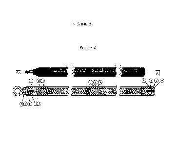
Figure 2 shows a split in section A revealing details of
the cable bar, such as: One bearing cover (m), one alien
screw (p), one bearing lockwasher (L), two deep protective
grooves (1), one swivel bearing housing (h), four wrist
bearings (e), one handle tube (f), two shims (g);
Figure 3 shows a section J, revealing internal details of
the wedges (g);
Figure 4 shows the cable bar shaft (a) with a section U
that identifies its internal design;
Figure 5 shows the tip of the shaft (c), also identifying
its internal design;
Figure 6 shows a split in the design of the shaft (a) of
the cable bar (1) that allows the identification of where
the shaft end (c) fits;
Figure 7 shows the bar tubes (d, f);
Figure 8 shows the bar tubes (d, f) with the pulse bearings (e);
Figure 9 demonstrates, the design of the pulse bearings (e);
Figure 10 demonstrates the design of the housing (h) of
the slewing bearings;
Figure 11 illustrates the design of the bearing's cover;
CA 03196203 2023- 4- 19
7
Figure 12 illustrates the design of the bearing lock
washers; and
Figure 13 shows the eyebolt (n).
[021] DETAILED DESCRIPTION - According to the figures,
it was possible to contemplate a bar (1) with the
following components: two tubes (d, f) ; an inner central
tube, herein identified as the cable bar shaft (a) ; four
wrist bearings (e) being fitted to each end of the tubes
(d, f) ; a shaft end (c) which connects to an eyebolt (n)
; three shims (g) situated on one side of each end of the
tubes (d, f) and one at the juxtaposition of the two
tubes; a slewing bearing housing (h) situated near the
bearing cap (m); a bearing lockwasher (L); and two deep
protective grooves (I) adjacent to the bearing housing
(h).
[022] The cable bar (1) has two rotating tubes or outer
sleeves (f, d) that are attached to the shaft or center
tube (a) of the bar (1). The main, central part (a) has a
cylinder below the tube, allowing it to rotate smoothly.
[023] The tubes (f, d) rotate freely in both directions,
without resistance or limitations.
[024] The eyebolt (n) is attached to the housing (h) of
the bar shaft (a) that penetrates the thread of the
CA 03196203 2023- 4- 19
8
eyebolt (n), ensuring that it does not unscrew during use.
[025] The eyebolt (n) also rotates freely in both
directions, and this ensures that it does not suffer any
mechanical stress, to prevent accidents from occurring.
[026] The housing (h) holds all the components in
place and makes it easier to attach the eyebolt (n) to
the shaft.
[027] This rotational movement was not possible with
traditional cable bars, because the wrists and hands are
forced to remain fixed to the bar, inhibiting the user's
ability to create opposing movements, and without this
function, it was impossible to connect the forearms to
the rest of the body, respecting the human gait cycle.
CA 03196203 2023- 4- 19