Note : Les descriptions sont présentées dans la langue officielle dans laquelle elles ont été soumises.
WO 2022/093089
PCT/SE2021/051009
1
A COMPOSITE PAPERBOARD CONTAINER WITH A RIM COMPRISING
FIBERS, AND A METHOD FOR PRODUCING SUCH A CONTAINER
TECHNICAL FIELD
The present disclosure relates to a composite paperboard container and a
method of
producing the composite paperboard container.
BACKGROUND OF THE INVENTION
In the area of disposable containers for products such as infant formula,
tobacco,
1_0 detergents, etc. there is an ongoing need of diminishing the carbon
footprint of such
products, by minimizing the resource use for the disposable containers as well
as making
the containers recyclable. The disposable containers referred to herein are
composite
containers having a tubular body which is made from a laminate sheet material
comprising a carton layer, i.e. a layer made predominantly from cellulosic
fibres. For
1_5 certain containers, the upper and lower end edge of the container include
a plastic rim
connected to the edges of the packaging container. This provides the packaging
containers with a pleasant and neat appearance and the container top or bottom
may also
be more wear resistant. To provide a container free from plastic components,
the top
and/or bottom portions of the container may alternatively be made from a
folded-in end
20 portion of the tubular body. The appearance may however for such packaging
containers
be somewhat less attractive and less wear resistant at the bottom end of the
packaging
container.
Paperbased materials have traditionally been considered less suitable for use
in making
25 covers and rims for paperboard containers as they have been considered to
have low
shape stability and to be less resistant to damage and wear than plastic
components. It
has also been difficult to attain secure and tight attachment to the
paperboard container
body of such components as well as a tight closure between a rim and a
container lid.
30 There is consequently a need to provide further packaging for sensitive
goods such as
food products with improved recyclability, without sacrificing durability or
packaging safety
for the packaged goods.
CA 03197016 2023- 4- 28
WO 2022/093089
PCT/SE2021/051009
2
SUMMARY OF THE INVENTION
The above object may be achieved with a composite paperboard container
according to
claim 1 and by a method of producing a composite paperboard container
according to
claim 11. Further advantages and advantageous features of the invention are
disclosed in
the following description and in the dependent claims
According to a first aspect, the present disclosure relates to a composite
paperboard
container for bulk solids. The composite paperboard container comprising a
tubular body
being closed at a bottom end over a container bottom opening opposite a
container top
opening at a top end of the tubular body. The tubular body has an inner
surface facing
towards an interior of the container body and an outer surface facing away
from the
interior of the container body. The tubular body extends in a longitudinal
direction. The
composite container comprises a rim surrounding the container top opening
and/or the
container bottom opening. The rim is attached at a connecting portion of the
rim to an end
portion of the tubular body along an end edge of the tubular body. The
connecting portion
of the rim has a distal edge. The tubular body is made from a laminate sheet
material
comprising a carton substrate layer and a thermoplastic welding layer. The rim
is a
molded rim comprising pulp fibers, such as softwood pulp fiber. The tubular
body is
connected to the rim by welding the end portion of the tubular body to the
connecting
portion of the rim. The distal edge of the connecting portion is located at a
distance from
the end edge of the tubular body of at least 4 mm, as seen in the longitudinal
direction of
the tubular body.
The rim is a molded rim comprising pulp fibers, the molded rim may be
constituted of from
95% to 100% of pulp fibers, such as softwood pulp fibers, optionally virgin
softwood pulp
fibers, optionally of from 98% to 100% of pulp fibers. Examples of such
materials which
have been developed for molding applications such as molded trays and
blisters, shaped
or embossed boxes, etc. are produced e.g. at Billerud GruvOn and sold as
Billerud
FibreForm . A similar material is the Advantage Formable paper available from
Mondi.
The tubular body of the composite paperboard container is made of a laminate
sheet
material comprising a carton substrate layer and an inner thermoplastic
welding layer. The
composite paperboard packaging container to which this disclosure relates is
intended to
store moisture-sensitive bulk solids, but is normally not intended to be
stored in a cooled
space, such as a refrigerator, and does therefore not need an outer polymeric
resin layer
CA 03197016 2023- 4- 28
WO 2022/093089
PCT/SE2021/051009
3
such as polyethylene. The tubular body of this type of composite paperboard
containers is
however often provided with an outer coating composition, such as a varnish,
to increase
the wear resistance and to provide an aesthetically pleasing packaging
container.
There is desire to provide packaging for sensitive goods such as food products
with
improved recyclability, without sacrificing durability or packaging safety for
the packaged
goods. However, since the rim is a molded rim comprising pulp fibers the
structure may
be less flexible and may also have a more irregular surface compared to a
conventional
plastic rim which may reduce the sealing tightness between the rim and the
tubular
paperboard body. Thereby, durability or packaging safety for packaged goods
may be
reduced since there could be a risk of air and/or moisture penetrating the
space between
the tubular body and the rim. It was however surprisingly found by the present
inventor,
that by providing a rim with a connecting portion extending at least 4 mm in
the
longitudinal direction from the end edge of the tubular body and welding the
rim to the
tubular body provided with an inner layer of a thermoplastic welding layer, a
satisfying
sealing tightness allowing packaging for sensitive goods such as food products
could be
achieved while yet providing a neat appearance at the bottom or upper
container edge on
an easily recyclable container. It has been found that a rim with a connecting
portion
extending at least 4 mm, in the longitudinal direction from the end edge of
the tubular
body, optionally of from 4 mm to 50 mm in the longitudinal direction from the
end edge of
the tubular body, optionally from 5 mm to 40 mm in the longitudinal direction
from the end
edge of the tubular body, provides an enhanced shape stability for the rim by
means of
the tubular body wall providing a support for the most fragile part of the
rim, namely the
connecting portion or connecting portions.
The rim is attached to an end portion of the tubular body and the end portion
of the tubular
body may either be around the container top opening or at the container bottom
opening.
The composite paperboard container may comprise a rim according to the present
disclosure around both the container top opening and the container bottom
opening.
The rim may be an inner rim and the composite paperboard container may
furthermore
comprise a lid component. The lid component may be a molded lid component
comprising
pulp fibers, such as softwood pulp fibers, and may be made from the same
material and in
the same manner as the inner rim. The lid component may comprise a lid part
and an
outer rim part, the outer rim part and the lid part may be moulded in one
piece and be
CA 03197016 2023- 4- 28
WO 2022/093089
PCT/SE2021/051009
4
connected to each other via a hinge portion. The outer rim part is connectable
to the inner
rim. The outer rim component may be mechanically connected to the inner rim,
such as
by a snap-on connection, a slide-in connection etc.
The rim may alternatively be part of a rim and lid component, wherein the rim
part and the
lid part of the rim and lid component may be moulded in one piece, the rim
part being
connected to the lid part via a hinge portion and the wherein the rim part is
welded to the
tubular body.
The rim may be connected either to the inner surface or to the outer surface
of the tubular
body via the first connecting portion. The first connecting portion is a
circumferential
connecting portion extending around the entire circumference of the tubular
body. The
first connecting portion is connected to the tubular body along the entire end
portion, to
the inner and/or to the outer surface of the tubular body.
The rim may be provided with a thermoplastic layer on a surface facing the
tubular body.
A thermoplastic layer provides the rim with a less irregular surface and,
thus, enhances
sealing and improves durability or packaging safety for the packaged goods.
The paperboard packaging container may be provided with an inner transport
closure
being attached to an inner surface of the tubular body at the top end and at a
distance
from said the rim, the transport closure may be a fully or partially removable
closure. A
fully or partly removable transport closure may be gastight or gas-permeable.
A gastight
closure may be manufactured from any material or material combination suitable
for
providing a gastight sealing of a compartment delimited by the transport
closure, such as
aluminium foil, silicon-coated paper, plastic film, or laminates thereof. A
gastight transport
closure is advantageous when the bulk solids stored in the packaging container
are
sensitive to air and/or moisture, and it is desirable to avoid contact of the
packaged bulk
solids with ambient air. Since the transport closure is a removable closure,
it does not
have an impact on recyclability of the composite paperboard container.
The composite paperboard container may be free from plastic components, such
as a
plastic rim component, lid component or bottom component. Such composite
paperboard
container, thus, allows the user to recycle the container without first
separating plastic
components from the tubular body.
CA 03197016 2023- 4- 28
WO 2022/093089
PCT/SE2021/051009
The rim may have a density within the range of from 0.2 to 1.5 kg/dm3,
optionally within
the range of from 0.2 to 1 kg/dm3, optionally within the range of from 0.4 to
0.8 kg/dm3.
The rim according to the present disclosure is a molded rim and therefore
needs to have a
structural durability, preferably a structural durability similar to a plastic
rim_ For rim
5 components which are to be connected to an additional rim part, such as an
inner rim
component and an outer rim component, the rim components need to have a
certain
flexibility and to be and to be able to be structurally stable.
The rim may comprise a U-shaped or a square edge U-shaped track portion, as
seen in a
cross-sectional view, comprising a first and a second side wall section, being
opposing
wall sections, and a bottom section facing the end edge of the tubular body. A
draft angle
between the bottom section and the first side wall section may be within the
range of from
zero to ten degrees, optionally within the range of from zero to five degrees.
Since the
tubular body wall is formed by a paperboard blank and thus a thin rectangular
cross
section, a draft angle within the range of from zero to ten degrees, or within
the range of
from zero to five degrees, will enable a tight fit between the tubular body,
the bottom
section and the first side wall section. This promotes a durability and
packaging safety for
the packaged goods.
A distance between the first side wall section and the second side wall
section may vary
less than 3 mm along the entire first and second side wall sections. This
implies that the
first side wall section and the second side wall have a constant distance. The
first and
second wall sections may therefore align well with the inner and outer surface
of the
tubular body and thus only leave a minor gap between the tubular and the first
side wall
section and the second side wall section of the rim.
The rim may comprise an L-shaped connecting portion, as seen in a cross-
section view,
comprising a first side wall section and a bottom section facing the end edge
of the tubular
body. The rim may also have a L-shaped cross-section. A draft angle, between
the bottom
section and the first side wall section, is within the range of from zero to
ten degrees, or
within the range of from zero to five degrees. The first side wall section may
be applied
against the inner surface of the tubular body and wherein the first side wall
section
corresponds to the connecting portion of the rim. This promotes a tight
fitting between the
L-shaped connecting portion and the tubular body end portion improving the
durability of
the packaged goods and the packaging safety.
CA 03197016 2023- 4- 28
WO 2022/093089
PCT/SE2021/051009
6
The rim may comprise a guiding side wall section extending from the first
connecting
portion, such as from the first side wall section. The guiding side wall
section is a section
having a greater distance to the tubular body than the first connecting
portion. The guiding
side wall section may be being an inclined wall section with an increasing
distance to the
tubular body as seen from the end edge of the tubular body and in a
longitudinal direction
of the tubular body. Since the rim is made from pulp fibers, the structure may
be more
fragile and less flexible than a plastic rim and may additionally imply a
greater friction
between the rim and the tubular paperboard body. To reduce the risk of
damaging either
the rim or the edge portion when attaching the rim to the tubular body, the
rim may
comprise a guiding side wall section extending from the first side wall
section. This may
be advantageous when the rim comprises a U-shaped or a square edge U-shaped
track
portion in which the end portion of the tubular body is inserted.
The tubular body may have a thermoplastic welding layer in a basis weight of
at least 15
g/m2, such as within the range of from 20 g/m2 to 160 g/m2, optionally 35 g/m2
to 140 g/m2,
or 40 g/m2 to 120 g/m2 on the laminate sheet material. It has been found by
the present
inventors that such basis weight of the thermoplastic welding layer provides
an enhanced
welding with a rim comprising pulp fibers. Conventionally, the rim is a
plastic rim and
welding between the plastic rim and a paperboard container comprising a
thermoplastic
welding layer is therefore facilitated. However, if the thermoplastic welding
layer has such
basis weight an improved sealing, being durable and moisture resistant,
between the
tubular body and the rim according to the present invention may be achieved.
The thermoplastic welding layer may comprise or consist of a polyethylene
layer.
The thermoplastic welding layer may comprise a metallic powder dispersed
therein or
metallised polymers.
The laminate sheet material may comprise a metallic foil layer, such as
aluminium foil.
The metal foil layer may be arranged between the carton substrate layer and
the
thermoplastic welding layer. A bonding layer, such as a thermoplastic bonding
layer, may
be arranged between the metallic foil layer and the carton substrate layer.
The metallic foil
layer may have a thickness of from 5 micrometer to 30 micrometer, such as from
5
micrometer to 15 micrometer, such as from 5.5 micrometer to 6.5 micrometer.
CA 03197016 2023- 4- 28
WO 2022/093089
PCT/SE2021/051009
7
A laminate body sheet material which may be used in a composite packaging
container as
disclosed herein may comprise one or more layers in addition to the mandatory
structural
carton substrate layer and the inner thermoplastic welding layer f) as
disclosed below. As
seen in order from the outside to the inside, the laminate body sheet material
may have
the following structure:
a) an optional polymeric coating, such as a laquer,
b) an optional printed and/or coloured layer
c) a carton substrate layer
d) an optional polymeric bonding layer, e.g. a polyethylene (PE) layer
e) an optional barrier layer, e.g. an aluminum (Al) foil barrier layer
t) an inner thermoplastic welding layer, such as a polyethylene (PE) layer.
The inner
thermoplastic welding layer may consist of two or more sub-layers, such as a
polyethylene (PE) layer and a low-density polyethylene (LDPE) layer. The
sublayers may
be coextruded to form the inside polymeric layer, or may be formed as separate
films
which are laminated together.
According to a second aspect, the present disclosure relates to a method of
producing a
composite paperboard container for bulk solids according to any one of the
preceding
claims, the method comprising the steps of;
a) bending a paperboard laminate sheet material comprising a carton substrate
layer
and a thermoplastic welding layer into a tube, the tube having a longitudinal
direction,
a radial direction perpendicular to the longitudinal direction, closing the
tube in the
longitudinal direction by joining overlapping or abutting side edges of the
paperboard
material thereby forming a tubular body, the tubular body having an inner
surface
facing towards an interior of the tubular body and an outer surface facing
away from
the interior of the tubular body;
b) imparting a predetermined cross-sectional shape to said tube;
c) closing the tubular body at a bottom end over a container bottom opening
opposite a
container top opening at a top end of the tubular body;
d) providing pulp fibers, such as softwood pulp fibers, into a molding tool
thereby
forming a three-dimensionally shaped rim component comprising pulp fibers, the
rim
comprising a connecting portion having a distal edge;
e) providing the the rim to an end portion of the tubular body along an end
edge of the
tubular body so that the rim surrounds the container top opening and/or the
container
CA 03197016 2023- 4- 28
WO 2022/093089
PCT/SE2021/051009
8
bottom opening, such that that the distal edge of the rim connecting portion
is located
at a distance from the end edge of the tubular body of at least 4 mm; and
f) attaching the connecting portion of the three-dimensionally
formed container
component to the end portion of the tubular body by welding, thereby forming
the
cornposite paperboard container.
The method may comprise that step d) includes forming the rim such that it
comprises a
U-shaped or a square edge U-shaped track portion, the U-shaped or square edge
U-
shaped track portion comprising a first and a second side wall section and a
bottom
section and wherein step e) includes arranging the rim such that the bottom
section faces
the end edge of the tubular body.
A draft angle, between the bottom section and the first side wall section, may
be within the
range of from zero to ten degrees, optionally within the range of from zero to
five degrees.
A distance between the first side wall section and second side wall section
may vary less
than 3 mm along the first and second side wall sections. This implies that the
first side
wall section and the second side wall section have a constant distance between
them and
therefore may align with the inner and outer surface of the tubular body,
leaving only a
minor gap between the tubular body and the first side wall section and the
second side
wall section of the rim.
The rim may have a density within the range of from 0.2 to 1.5 kg/dm3,
optionally within
the range of from 0.2 to 1 kg/dm3, optionally within the range of from 0.4 to
0.8 kg/dm3.
For rim components which are to be connected to an additional rim part, such
as an inner
rim component and an outer rim component, the rim components need to have a
certain
flexibility and to be able to be structurally stable.
BRIEF DESCRIPTION OF THE DRAWINGS
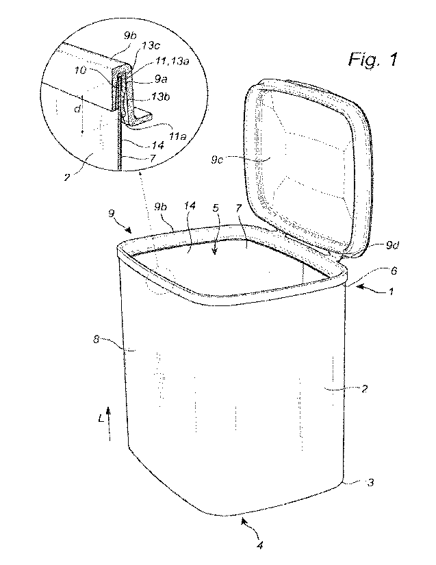
Figs. 1 illustrates a composite paperboard container according to
the present
disclosure;
Fig. 2 illustrates a paperboard blank;
Fig. 3 illustrates folding of the paperboard blank to a
tubular body;
Figs. 4-5 illustrate inserting a paperboard disc into the
tubular body thereby forming a
container bottom;
CA 03197016 2023- 4- 28
WO 2022/093089
PCT/SE2021/051009
9
Fig. 6 illustrates molding of pulp fibers to form a rim and
lid component;
Fig. 7 illustrates the molded rim comprising an inner rim
component and an outer
rim and lid component;
Fig. 8 illustrates attaching the inner rim component to the
tubular body by welding;
and
Fig. 9 illustrates attaching the outer rim and lid component
to the inner rim
component and thereby forming a composite paperboard container prepared
by the method according to the present disclosure.
DETAILED DESCRIPTION
It is to be understood that the drawings are schematic and that individual
components,
such as layers of materials and container components are not necessarily drawn
to scale.
The composite paperboard container and the steps in the method of forming a
composite
paperboard container shown in the figures are provided as examples only and
should not
be considered limiting to the invention. Accordingly, the scope of the
invention is
determined solely by the scope of the appended claims.
Figure 1 illustrates a composite paperboard container 1 for bulk solids, the
composite
paperboard container 1 comprising a tubular body 2 being closed at a bottom
end 3 over
a container bottom opening 4 opposite a container top opening 5 at a top end 6
of the
tubular body 2. The tubular body 2 has an inner surface 7 facing towards an
interior of the
container body 2 and an outer surface 8 facing away from the interior of the
container
body 2. The tubular body 2 extends in a longitudinal direction L between the
bottom end 3
and the top end 6. The composite container 1 comprises a rim 9 surrounding the
container top opening 5. The rim 9 is a molded inner rim 9a comprising pulp
fiber, such as
softwood pulp fibers. The inner rim 9a is attached to the tubular body 2 by
welding a
connecting portion 11 of the inner rim 9a to an end portion 10 of the tubular
body 2 along
an end edge 12 of the tubular body 2. The connecting portion 11 of the inner
rim 9a has a
distal edge 11a, the rim is located at a distance d from the end edge 12 of
the tubular
body within the range of from 4 mm to 50 mm.
The composite container 1 furthermore comprises a lid component including an
outer rim
part 9b and a lid part 9c. The outer rim part 9b and the lid part 9c are
moulded in one
piece. The outer rim part 9b is connected to the lid part 9c via hinge
portions 9d. The
CA 03197016 2023- 4- 28
WO 2022/093089
PCT/SE2021/051009
outer rim part 9b is connected to the inner rim 9a, the outer rim part 9b may
be connected
by a snap-on function, a slide-in connection, by means of adhesive or any
other suitable
means. The lid component is made from the same material as the inner rim 9a.
5 The inner rim 9a comprises a square edge U-shaped track portion 13, as seen
in a cross-
section view, comprising a first and a second side wall section 13a,13b and a
bottom
section 13c facing the end edge 12 of the tubular body 2. The first side wall
section 13a
corresponds to the connecting portion 11 of the inner rim 9a. However, the
inner rim may
have an L-shaped cross-section, with a first side wall section corresponding
to the
10 connecting portion of the rim and a bottom section arranged to face the end
edge 12 of
the tubular body 2.
The tubular body 2 is made from a laminate sheet material comprising a carton
substrate
layer and a thermoplastic welding layer 14.
Figs. 2 to 9 show a method of producing a composite paperboard container 1 for
bulk
solids. Fig. 2 illustrates a paperboard laminate sheet material 2" comprising
a carton
substrate layer and a thermoplastic welding layer 14. The laminate sheet
material 2" has
opposing side edges 16,17. Fig. 3 shows a first step a) of bending the
paperboard
laminate sheet material 2" into a tube 2', the tube 2' having a longitudinal
direction L, and
closing the tube 2' in the longitudinal direction L by joining abutting side
edges 16,17 of
the paperboard material 2" and thereby forming a tubular body 2. The join
between the
side edges 16,17 may be covered by a sealing strip. The side edges 16,17 may
alternatively be joined being overlapping. The tubular body 2 formed has an
inner surface
7 facing towards an interior of the tubular body 2 and an outer surface 8
facing away from
the interior of the tubular body 2. The thermoplastic welding layer 14 of the
laminate sheet
material is arranged on the inner surface 7 of the tubular body 2. The tube is
shaped to
have a predetermined cross-sectional shape. In the example shown in the
figures, the
cross-sectional shape is a modified rectangular shape with rounded corners. It
is to be
understood that the tubular body may have any useful cross-sectional shape
such as
circular shape, oval shape, or any polygonal or modified polygonal shape such
as
triangular shape, square shape, pentagonal shape, etc.
Figs. 4 and 5 illustrate a step c) of closing the tubular body 2 at a bottom
end 3 over a
container bottom opening 4 opposite a container top opening 5 at a top end 6
of the
CA 03197016 2023- 4- 28
WO 2022/093089
PCT/SE2021/051009
11
tubular body 2. The bottom opening 4 is closed by pressing by pressing a
paperboard
bottom disc 18 into the tube at the bottom end 3. The bottom disc 18 has a
peripheral
flange 18a being flexed towards the bottom end 3 in the longitudinal direction
L. The
flexed peripheral flange 18a may be attached to the inner surface 7 of the
tubular body 2
for example by welding. The paperboard bottom disc 18 may be constituted of a
laminate
sheet material comprising a carton substrate layer and a thermoplastic welding
layer. A
bottom rim may be applied to the bottom end 3 of the tubular body, the bottom
rim may be
a molded rim comprising pulp fibers according to the present disclosure and
may be
applied by welding according to the present disclosure or may be adhesively
attached.
Figs. 6 illustrates a step of forming the lid component including the outer
rim part 9b and
the lid part 9c. The molded outer rim and lid part are formed by providing
softwood pulp
fibers, such as in the form of a pulp slurry, in a molding tool 15. The
molding tool 15
comprises a female molding tool component 15a and a mating male molding tool
component 15b between which the pulp fibers are pressed to form a three-
dimensionally
shaped lid component comprising pulp fibers. The inner rim 9a (illustrated in
Fig. 7 being
molded in a corresponding manner).
Fig. 7 illustrates an inner rim 9a and a lid component including an outer rim
part 9b and a
lid part 9c molded in one piece and the outer rim component 9b being connected
to the lid
component 9c via two hinge portions 9d.
The inner rim 9a has a square U-shaped track portion 13, as seen in a cross-
section view,
comprising a first and a second side wall section 13a,13b and a bottom section
13c,
intended to face the end edge 12 of the tubular body 2. The first side wall
section 13a
corresponds to the connecting portion 11 of the inner rim 9a. However, the rim
may
equally be of an L-shape, with a first side wall section corresponding to the
connecting
portion of the rim and a bottom section intended to face the end edge 12 of
the tubular
body 2. A draft angle a, between the bottom section 13c and the first side
wall section
13a, is within the range of from zero to ten degrees.
Fig. 8 illustrates a step of attaching the inner rim 9a by means of welding
the inner rim 9a
to the end portion 10 of the tubular body 2 along the end edge 12 of the
tubular body 2, so
that the inner rim 9a surrounds the container top opening 5. The welding is in
this figure
performed by a welding unit 19 comprising an induction coil 19a and a press
plunger 19b.
CA 03197016 2023- 4- 28
WO 2022/093089
PCT/SE2021/051009
12
The welding unit 19 comprises a high frequency induction welding unit
comprising an
induction coil 19a. The press plunger 19b comprises an expandable welding tool
51 which
is transformable between an unexpanded state, and a radially expanded state.
In the expanded state, a cross-sectional area (footprint) delimited by the
outer
circumference of the welding tool 51 is larger than in the unexpanded state of
the welding
tool 51.
When the press plunger 19b is inserted into the tubular body 2 with the
welding tool 51 in
the attachment position for the inner rim 9a, the welding tool 51 is
transformed to the
expanded state.
In the expanded state of the welding tool 51, an edge portion of the outer
circumference of
the welding tool 51 contacts the inner rim 9a which is inserted into the
tubular body 2 and
exerts pressure on the inner rim 9a such that it is pressed against the inside
of the tubular
body 2 and can be induction welded to the inside of the tubular body 2 by
activating the
induction coil 19a.
Figs. 9 illustrates when the inner rim 9a is attached to the end portion 10 of
the tubular
body 2 and the step of attaching the outer rim and lid parts 9b,9c to the
inner rim 9a by a
snap-fit attachment.
CA 03197016 2023- 4- 28