Note : Les descriptions sont présentées dans la langue officielle dans laquelle elles ont été soumises.
CA 03199242 2023-04-20
WO 2022/182491
PCT/US2022/015067
CONTROL SYSTEM FOR A HEATING, VENTILATION, AND AIR--
CONDITIONING SYSTEM
BACKGROUND
100011 This section is intended to provide relevant background
information to
facilitate a better understanding of the various aspects of the described
embodiments.
Accordingly, these statements are to be read in this light and not as
admissions of prior
art.
100021 In general, heating, ventilation, and air-conditioning ("HVAC") systems
circulate an indoor space's air over low-temperature (for cooling) or high-
temperature
(for heating) sources, thereby adjusting an indoor space's ambient air
temperature.
HVAC systems generate these low- and high-temperature sources by, among other
techniques, taking advantage of a well-known physical principle: a fluid
transitioning
from gas to liquid releases heat, while a fluid transitioning from liquid to
gas absorbs
heat.
[00031 Within a typical variable capacity HVAC system, a fluid refrigerant
circulates
through a closed loop of tubing that uses a compressor, which receives DC
power from
an inverter, and flow-control devices to manipulate the refrigerant's flow and
pressure,
causing the refrigerant to cycle between the liquid and gas phases. Generally,
these
phase transitions occur within the :HVAC system heat exchangers, which are
part of the
closed loop and designed to transfer heat between the circulating refrigerant
and
flowing ambient air. As would be expected, the heat exchanger providing
heating or
cooling to the climate-controlled space or structure is described adjectivally
as being
"indoors," and the heat exchanger transferring heat with the surrounding
outdoor
environment is described as being "outdoors."
10004] The refrigerant circulating between the indoor and outdoor heat
exchangers,
transitioning between phases along the way, absorbs heat from one location and
releases
it to the other. Those in the HVAC industry describe this cycle of absorbing
and
releasing heat as "pumping.' To cool the climate-controlled indoor space, heat
is
"pumped" from the indoor side to the outdoor side, and the indoor space is
heated by
.. doing the opposite, pumping heat from the outdoors to the indoors.
10005] Additionally, some HVAC systems include dampers installed within supply
ducting, as well as a bypass duct with a bypass damper. The bypass duct
relieves excess
CA 03199242 2023-04-20
WO 2022/182491
PCT/US2022/015067
static pressure created when one or more supply duct dampers are closed during
heating
or cooling by flowing a portion of the airflow from the blower into a return
duct.
However, the bypass duct and bypass damper increases the initial cost of the
HVAC
system and increases the time required to install the HVAC system.
BRIEF DESCRIPTION OF THE DRAWINGS
100061 Embodiments of -the HVAC system are described with reference to the
following figures. The same numbers are used throughout the figures to
reference like
features and components. The features depicted in the figures are not
necessarily shown
to scale. Certain features of the embodiments may be shown exaggerated in
scale or in
somewhat schematic form, and some details of elements may not be shown in the
interest of clarity and conciseness.
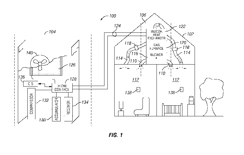
100071 FIG. 1 is a schematic of an HVAC system, according to one or more
embodiments;
100081 FIG. 2 is a simplified block diagram of an HVAC system 200, according
to
one or more embodiments;
100091 FIG. 3 is a flowchart of a method of operating an HVAC system,
according to
one or more embodiments; and
100101 FIG. 4 is a block diagram of a controller, according to one or more
embodiments.
DETAILED DESCRIPTION
100111 The present disclosure describes an HVAC system having a zoning mode
selection. Enabling zoning mode in the control system for the EINTAC system
allows the
HVAC control system operate a blower, which flows air into climate-controlled
spaces
via ducts, across a broad range of air flow rates to meet low cooling or
heating demands
on the HVAC system without the use of a bypass duct and bypass damper. This is
accomplished by reducing the air flow rate produced by the blower below what
is
typically the minimum air flow rate produced by a blower.
100121 Turning now to the figures, FIG. I shows an HVAC system 100 that
provides
heating and cooling for a residential structure 102. However, the concepts
disclosed
herein are applicable to numerous of heating and cooling situations, which
include
residential; industrial, and commercial settings.
2
CA 03199242 2023-04-20
WO 2022/182491
PCT/US2022/015067
100131 The
describediFIVAC system 100 is divided into two primary portions: (1)
the outdoor unit 104, which mainly comprises components for transferring heat
with
the environment outside the structure 102; and (2) the indoor unit 106, which
mainly
comprises components for transferring heat with the air inside the structure
102. To
heat or cool the illustrated structure 102, the indoor unit 106 draws ambient
indoor air
via return ducts 110, passes that air over one or more heating/cooling
elements (i.e.,
sources of heating or cooling), and then routes that conditioned air, whether
heated or
cooled, back to the various climate-controlled spaces 112 through the supply
ducts or
ductworks 114 ___________________________________________________________
which are relatively large conduits that may be rigid or flexible. A
blower 116 provides the motivational force to circulate the ambient air
through the
return ducts 110 and the supply ducts 114. The supply ducts 114 may also
include
dampers 118 to control the flow of conditioned air into specific areas of the
structure
102. Additionally, although a split system is shown in FIG.1, the disclosed
embodiments can be equally applied to the packaged or other types of the HVAC
system configurations.
100141 As
shown, the HVAC system 100 is a "dual-fuel" system that has multiple
heating elements, such as an electric heating element or a gas furnace 120.
The gas
furnace 120 located downstream (in relation to airflow) of the blower 116
combusts
natural gas to produce heat in furnace tubes (not shown) that coil through the
gas
furnace 120. These furnace tubes act as a heating element for the ambient
indoor air
being pushed out of the blower 116, over the furnace tubes, and into the
supply ducts
114. However, the gas furnace 120 is generally operated when robust heating is
desired.
During conventional heating and cooling operations, air from the blower 116 is
routed
over an indoor heat exchanger 122 and into the supply ducts 114. The blower
116, the
gas furnace 120, and the indoor heat exchanger 122 may be packaged as an
integrated
air handler unit, or those components may be modular. In other embodiments,
the
positions of the gas furnace 120, the indoor heat exchanger 122, and the
blower 116
can be reversed or rearranged.
100151 The
indoor heat exchanger 122 acts as a heating or cooling means that adds
or removes heat from the structure, respectively, by manipulating the pressure
and flow
of refrigerant circulating within and between the indoor and outdoor units via
refrigerant lines 124. Alternatively, the refrigerant could be circulated to
only cool (i.e.,
extract heat from) the structure, with heating provided independently by
another source,
3
CA 03199242 2023-04-20
WO 2022/182491
PCT/US2022/015067
such as, but not limited to, the gas furnace 120. There may also be no heating
of any
kind. liVAC systems 100 that use refrigerant to both heat and cool the
structure 102
are often described as heat pumps, while FIVAC systems 100 that use
refrigerant only
for cooling are commonly described as air conditioners.
100161 Whatever the
state of the indoor heat exchanger 122 (i.e., absorbing or
releasing heat), the outdoor heat exchanger 126 is in the opposite state. More
specifically, if heating is desired, the illustrated indoor heat exchanger 122
acts as a
condenser, aiding transition of the refrigerant from a high-pressure gas to a
high-
pressure liquid and releasing heat in the process. The outdoor heat exchanger
126 acts
as an evaporator, aiding transition of the refrigerant from a low-pressure
liquid to a low-
pressure gas, thereby absorbing heat from the outdoor environment. If cooling
is
desired, the outdoor unit 104 has flow control devices 128 that reverse the
flow of the
refrigerant, allowing the outdoor heat exchanger 126 to act as a condenser and
allowing
the indoor heat exchanger 122 to act as an evaporator.
Fowl The flow control devices 128 may also act as an expansion device to
reduce
the pressure of the refrigerant flowing therethrough. In other embodiments,
the
expansion device may be a separate device located in either the outdoor unit
104 or the
indoor unit 106. To facilitate the exchange of heat between the ambient indoor
air and
the outdoor environment in the described MAC system 100, the respective heat
exchangers 122, 126 have tubing that winds or coils through heat-exchange
surfaces,
to increase the surface area of contact between the tubing and the surrounding
air or
environment.
100181 The
illustrated outdoor unit 104 may also include an accumulator 130 that
helps prevent liquid refrigerant from reaching the inlet of a compressor 132.
The
outdoor unit 104 may include a receiver 134 that helps to maintain sufficient
refrigerant
charge distribution in the I-IVAC system 100, The size of these components is
often
defined by the amount of refrigerant employed by the tIVAC system 100.
100191 The
compressor 132 receives low-pressure gas refrigerant from either the
indoor heat exchanger 122 if cooling is desired or from the outdoor heat
exchanger 126
if heating is desired. The compressor 132 then compresses the gas refrigerant
to a higher
pressure based on a compressor volume ratio, namely the ratio of a discharge
volume,
the volume of gas outputted from the compressor 132 once compressed, to a
suction
4
CA 03199242 2023-04-20
WO 2022/182491
PCT/US2022/015067
volume, the volume of gas inputted into the compressor 132 before compression.
In the
illustrated embodiment, the compressor is a multi-stage compressor 132 that
can
transition between at least two volume ratios depending on whether heating or
cooling
is desired. In other embodiments, the HVAC system 100 may be configured to
only
cool or only heat, and the compressor 132 may be a single-stage compressor
having
only a single volume ratio.
100201 A
control system 136 controls the blower 116, based on the required heating
or cooling that must be provided by the 1-IVAC system, i.e., the demand on the
HVAC
system 100, as well as settings input by a user via an input device, such as,
but not
limited to, a thermostat 138 or a control panel of the HVAC system 100, and/or
the
operational status of the FIVAC. system 100. Although the control system is
shown as
a single component of the outdoor unit 1.04, the invention is not thereby
limited, In
another embodiment, the control system 136 may be located within the climate-
controlled area 112. In other embodiments, the control system 136 may be made
up of
multiple control systems or controllers, as described below with reference to
FIG. 4,
positioned at various points within the HVAC system and/or climate-controlled
area
112 that are in electronic communication with each other.
[0021] In
some embodiments, the control system 136 may also adjust the position
of the dampers 118, the air flow rate produced by a fan 140 that blows air
across the
outdoor heat exchanger 126, and the speed of the compressor 132. The control
system
1.36 may further control the switching between compressor stages for multi-
stage
compressors. Although the thermostats 138 are shown as a separate from the
indoor
unit 106, other embodiments, such as, but not limited to packaged HVAC
systems, may
include a thermostat 138 that is integrated into the indoor unit 106.
Additionally, other
embodiments may include more than two thermostats 138.
[0022] The
control system 136 determines the cooling or heating demand on the
HVAC system 100 based on the user input, such as a desired temperature,
desired
temperature range, or a desired humidity, the positions of the dampers 118,
and/or data
from sensors within the thermostats 138 or sensors placed within the structure
102
and/or throughout the HVAC system 100. The data measured by the sensors may
include, but is not limited to, the temperature within the climate-controlled
area 112,
the humidity within the climate-controlled area 112, the temperature outside
of the
structure 102, the humidity outside of the structure 102, and refrigerant
pressure within
5
CA 03199242 2023-04-20
WO 2022/182491
PCT/US2022/015067
the HVAC system. The HVAC system 100 may include any number of sensors 142 and
input devices, each of which can accept a user input.
100231
Referring now to FIG. 2, FIG. 2 shows a block diagram of an IINTAC system
200. The HVAC system 200 includes an outdoor heat exchanger 226, an expansion
device 228, an indoor heat exchanger 222, and a compressor 232. Additionally,
the heat
exchangers 222, 226 may be either condensers or evaporators, depending on the
configuration of the HVAC system 200. The HVAC system 200 may also include the
equipment shown in FIG. 1 and function as discussed above with reference to
FIG. I.
Accordingly, the function of the outdoor heat exchanger 226, the expansion
device 228,
the indoor heat exchanger 222, and the compressor 232 will not be discussed in
detail
except as necessary for the understanding of the HVAC system 200 shown in FIG.
2.
100241 When
cooling is desired, high-pressure refrigerant flows from the
compressor 232 to the outdoor heat exchanger 226, where it is condensed. The
high-
pressure liquid refrigerant then flows to the expansion device 228, where it
is expanded
to low-pressure refrigerant. The low-pressure refrigerant is then evaporated
in the
indoor heat exchanger 222 and the low-pressure vapor flows into the compressor
232
as a vapor, to begin the cycle again. When the HVAC system 200 is operating as
a heat
pump, the flow of refrigerant is reversed. A blower 216 flows air 202 over the
indoor
heat exchanger 222 to provide a climate-controlled space with conditioned air,
100251 As shown in FIG. 2, the ID/AC system 200 includes a control system
236 in
electronic communication with the blower 216 and an input device 238. The
input
device 238 is configured to allow a user to select if zoning mode is enabled
or disabled.
When zoning mode is disabled, the control system 236 operates the blower 216
within
a first air flow rate range, e.g., between 70% and 100% of the rated cubic
feet per minute
("CFM") of the blower 216, depending on the demand on the :HVAC system 200.
However, this may still produce more airflow than is necessary to meet the
demand on
the FIVAC system 200. When zoning mode is enabled, the control system 236
operates
the blower within a second air flow rate range that allows for a lower air
flow rate than
the first range, e.g., between 40% and 100% of the rated ('FM of the blower
216. The
lower minimum air flow rate of the second range allows the blower 216 to move
a
reduced amount of air through the indoor heat exchanger when there is less
demand on
the HVAC system, thereby more efficiently addressing the demand on the HVAC
system by running the blower at a lower air flow rate instead of utilizing a
bypass duo.
6
CA 03199242 2023-04-20
WO 2022/182491
PCT/US2022/015067
to flow air into a return duct.
10026] The
input device may also allow the user to select fixed offset for the blower
216. When a fixed offset is entered to reduce the air flow rate produced by
the blower
216, the control system may reduce the percentages of the first air flow rate
range by a
fixed amount or percentage, e.g., with a 15% offset entered for the first air
flow rate
range above, the control system 236 would operate the blower 216 between 55%
and
85% of the rated CFM. Similarly, when a fixed offset is entered to increase
the air flow
rate produced by the blower 216, the control system may increase the lower
amount or
percentage of the first air flow rate range by a fixed amount or percentage,
e.g., with a
15% offset entered for the first air flow rate range above, the control system
236 would
operate the blower 216 between 85% and 100% of the rated CFM
100271 The
control system 236 is also in electronic communication with the
compressor 232, the outdoor heat exchanger 226, the expansion device 228, and
the
indoor heat exchanger 222. The control system 236 receives information from
sensors
on one or more of these components of the HVAC system 200 to determine if
protection
controls, such as, but not limited to, defrost control and oil recovery
control, need to be
implemented. When protection controls are implemented by the control system
236, the
zone control selection is overridden and the blower is operated according to
the
requirements of the specific protection control, which typically falls within
the first air
flow rate range. The control system 236 may also monitor the HVAC system 200
to
determine if the HVAC system 200 is performing startup operations. Similar to
when
protection controls are implemented, the zone control selection is overridden
and the
blower is operated according to the requirements of the startup operations,
which
typically falls within the first air flow rate range.
100281 FIG. 3 is a flowchart of method of operating an HVAC system. The
method
may be performed by a control system, such as the control systems 136, 236
discussed
above. The illustrated method allows the control system to operate a blower
across a
larger air flow rate range to better meet lesser cooling or heating demands on
the HVAC
system.
100291 In step 300, the control system determines the demand on the HVAC
system.
As discussed above, the demand on the EIVA.0 system is based on user inputs,
such as
a desired temperature, desired temperature range, and/or a desired humidity,
and/or data
7
CA 03199242 2023-04-20
WO 2022/182491
PCT/US2022/015067
from the thermostat or sensors placed throughout the 1-WAC system. The data
measured
by the sensors may include, but is not limited to, the temperature within a
climate-
controlled area, the humidity within the climate-controlled area 112, the
temperature
outside of the structure 102, the humidity outside of the structure 102, and
refrigerant
pressure within the FIVAC. system.
100301 In step 302, the control system determines if zoning mode is
enabled based
on a user input. If zoning mode is disabled, the control system operates the
blower
within the first air flow rate range based on the demand on the 1-RAC system,
as shown
in step 304. The control system may also operate the blower within the first
range based
on other considerations, such as protection controls and startup operations.
10031.1 If zoning mode is enabled, the control system then determines if
the 1-1VAC
system is performing startup operations, as shown in step 306. If the HVAC
system is
performing startup operations, the control system operates the blower
according to the
requirements of the startup operations, as shown in step 308.
100321 If the HVAC system is not performing startup operations, the control
system
then determines if a protection control are required, as shown in step 310.
The control
system determines if the protection control is required based on measurements
from
sensors placed throughout the components of the FIVAC system. If a protection
control
is required, the control system operates the blower according to the
requirements of the
protection control, as shown in step 312. If protection controls are not
required, the
control system operates the blower within the second air flow rate range based
on the
demand on the I-IVAC system, as shown in step 314,
100331 :FIG. 4 is a block diagram of a controller 400 that can be used
to control the
blower of an HVAC system, such as in the control systems 136, 236 described
above.
The controller 400 includes at least one processor 402, a non-transitory
computer
readable medium 404, an optional network communication module 406, optional
inpudoutput devices 408, and an optional display 410 all interconnected via a
system
bus 412. In at least one embodiment, the input/output device 408 and the
display 410
may be combined into a single device, such as a touch-screen display. Further,
the
display 410 may also include a temperature sensor that monitors the
temperature within
the climate-controlled area. Software instructions executable by the processor
402 for
implementing software instructions stored within the controller 400 in
accordance with
8
CA 03199242 2023-04-20
WO 2022/182491
PCT/US2022/015067
the illustrative embodiments described herein, may be stored in the non-
transitory
computer readable medium 404 or some other non-transitory computer-readable
medium.
[0034]
Although not explicitly shown in FIG. 4, it will be recognized that the
controller 400 may be connected to one or more public and/or private networks
via
appropriate network connections. It will also be recognized that software
instructions
may also be loaded into the non-transitory computer readable medium 404 from
an
appropriate storage media or via wired or wireless means.
100351 Further examples include:
100361 Example 1 is a control system for a HVAC system for a structure and
comprising a blower that flows air over an indoor heat exchanger. The control
system
includes a first input device, a first sensor, and a processor in electronic
communication
with the first input device, the first sensor, and the blower of the HVAC
system. The
first input device is operable to accept a zoning mode selection. The first
sensor is
sensor operable to measure a first temperature at a first location within the
structure.
The processor is programmed to determine a cooling or heating demand on the
HVAC
system based on an input temperature and the first measured temperature. The
processor
is further programmed to adjust an air flow rate produced by the blower based
on the
demand on the HVAC system and the zoning mode selection.
100371 In Example 2, the embodiments of any preceding paragraph or
combination
thereof further include wherein the first input device is further operable to
accept the
input temperature.
[0038] In
Example 3, the embodiments of any preceding paragraph or combination
thereof further include a second input device and a second sensor operable to
measure
a second temperature at a second location within the structure, The first and
second
input devices are both operable to accept the input temperature and the zoning
mode
selection. The processor is further programmed to also determine the demand on
the
HVAC system based on the second measured temperature,
[0039] In
Example 4, the embodiments of any preceding paragraph or combination
thereof further include wherein when zoning mode is disabled, the control
system. is
operable to operate the blower within a first air flow rate range having a
first minimum
air flow rate. When zoning mode is enabled, the control system is operable to
operate
9
CA 03199242 2023-04-20
WO 2022/182491
PCT/US2022/015067
the blower within a second air flow rate range having a second minimum air
flow rate
that is lower than the first minimum air flow rate.
[0040]
Example 5 is an EIVA.0 system for a structure having ductwork. The HVAC
system includes a refrigeration circuit comprising a compressor, an outdoor
heat
exchanger, an expansion device, and an indoor heat exchanger. The HIVA.0
system also
includes a blower that flows air over the indoor heat exchanger and through
the
ductwork. The HVAC system further includes a control system including a first
input
device, a first sensor, and a processor in electronic communication with the
first input
device, the first sensor, and the blower of the HVAC system. The first input
device is
operable to accept a zoning mode selection. The first sensor is sensor
operable to
measure a first temperature at a first location within the structure. The
processor is
programmed to determine a cooling or heating demand on the HVAC system based
on
an input temperature and the first measured temperature. The processor is
further
programmed to adjust an air flow rate produced by the blower based on the
demand on
the :FIVAC. system and the zoning mode selection.
100411 In
Example 6, the embodiments of any preceding paragraph or combination
thereof further include wherein the first input device is further operable to
accept the
input temperature.
100421 In
Example 7, the embodiments of any preceding paragraph or combination
thereof further include wherein the control system further includes a second
input
device and a second sensor. The second input device is operable to accept at
least one
of the input temperature or the zoning mode selection. The second sensor is
operable to
measure a second temperature at a second location within the structure.
Determining
the demand on the EIVA.0 system inlcudes determining the demand on the HVAC
system based on the input temperature, the first measured temperature, and the
second
measured temperature.
[0043] In
Example 8, the embodiments of any preceding paragraph or combination
thereof further include dampers installable within the ductwork. The processor
is in
electronic communication with the dampers. The processor is further programmed
to
adjust a position of one or more of the dampers.
[0044] In
Example 9, the embodiments of any preceding paragraph or combination
thereof further include wherein the processor is further programmed to adjust
the air
CA 03199242 2023-04-20
WO 2022/182491
PCT/US2022/015067
flow rate produced by the blower based also on the position of the dampers.
100451 In Example 10, the embodiments of any preceding paragraph or
combination
thereof further include wherein the ductwork does not include a bypass duct
and the
HVAC system does not include a bypass damper installable within the bypass
duct.
[0046] In Example 11, the embodiments of any preceding paragraph or
combination
thereof further include sensors operable to monitor a status of at least one
of the
compressor, the indoor heat exchanger, the outdoor heat exchanger, or the
expansion
device and communicate information on the status with the control system. The
processor is further programmed to adjust the air flow rate produced by the
blower
based also on the information from the sensors.
[0047] In Example 12, the embodiments of any preceding paragraph or
combination
thereof further include wherein the processor is further programed to
determine if a
startup operation is occurring and adjust the air flow rate produced by the
blower based
also on the startup operation determination.
[0048] In Example 13, the embodiments of any preceding paragraph or
combination
thereof further include wherein when zoning mode is disabled, the control
system is
operable to operate the blower within a first air flow rate range having a
first minimum
air flow rate. When zoning mode is enabled, the control system is operable to
operate
the blower within a second air flow rate range having a second minimum air
flow rate
that is lower than the first minimum air flow rate.
100491 Example 14 is a method of operating an HVAC system. The method includes
identifying a zoning mode selection and an input temperature. The method also
includes
measuring a first temperature at a first location within a structure. The
method further
includes determining a demand on the HVAC system based on the input
temperature
.. and the first measured temperature. The method also includes adjusting air
flow rate
produced by a blower of the HVAC system based on the demand on the HVAC system
and the zoning mode selection.
100501 In Example 15, the embodiments of any preceding paragraph or
combination
thereof further include measuring a second temperature at a second location
within the
structure, wherein determining the demand on the HVAC system further comprises
also
determining the demand on the HVAC system based on the second measured
temperature.
11
CA 03199242 2023-04-20
WO 2022/182491
PCT/US2022/015067
100511 In
Example 16, the embodiments of any preceding paragraph or combination
thereof further include adjusting a position of one or more dampers installed
in
ductwork of the structure, wherein adjusting the air flow rate produced by the
blower
comprises adjusting the air flow rate produced by the blower based on the
demand on
.. the FIVA.0 system, the zoning mode selection, and the position of the
dampers.
100521 In
Example 17, the embodiments of any preceding paragraph or combination
thereof further include wherein the ductwork does not include a bypass duct
and the
one or more dampers does not include a bypass damper instal led within the
bypass duct.
10053] In
Example 18, the embodiments of any preceding paragraph or combination
thereof further include monitoring a status of at least one of a compressor of
the IIVA.0
system, an indoor heat exchanger of the HVAC system, an outdoor heat exchanger
of
the HVAC system, or an expansion device of the HVAC system via sensors,
wherein
adjusting the air flow rate produced by the blower comprises adjusting the air
flow rate
produced by the blower based on the demand on the HVAC system, the zoning mode
selection, and information from the sensors.
100541 In
Example 19, the embodiments of any preceding paragraph or combination
thereof further include determining if a startup operation is in occurring,
wherein
adjusting the air flow rate produced by the blower comprises adjusting the air
flow rate
produced by the blower based on the demand on the HVAC system, the zoning mode
selection, and the startup operation determination.
100551 In
Example 20, the embodiments of any preceding paragraph or combination
thereof further include when zoning mode is disabled, the control system is
operable to
operate the blower within a first air flow rate range having a first minimum
air flow
rate. When zoning mode is enabled, the control system is operable to operate
the blower
within a second air flow rate range having a second minimum air flow rate that
is lower
than the first minimum air flow rate.
100561
Certain terms are used throughout the description and claims to refer to
particular features or components. As one skilled in the art will appreciate,
different
persons may refer to the same feature or component by different names. This
document
does not intend to distinguish between components or features that differ in
name but
not function.
100571 For
the embodiments and examples above, a non-transitory computer
12
CA 03199242 2023-04-20
WO 2022/182491
PCT/US2022/015067
readable medium can comprise instructions stored thereon, which, when
performed by
a machine, cause the machine to perform operations, the operations comprising
one or
more features similar or identical to features of methods and techniques
described
above. The physical structures of such instructions may be operated on by one
or more
processors. A system to implement the described algorithm may also include an
electronic apparatus and a communications unit. The system may also include a
bus,
where the bus provides electrical conductivity among the components of the
system.
The bus can include an address bus, a data bus, and a control bus, each
independently
configured. The bus can also use common conductive lines for providing one or
more
of address, data, or control, the use of which can be regulated by the one or
more
processors. The bus can be configured such that the components of the system
can be
distributed. The bus may also be arranged as part of a communication network
allowing
communication with control sites situated remotely from system.
100581 In
various embodiments of the system, peripheral devices such as displays,
additional storage memory, and/or other control devices that may operate in
conjunction with the one or more processors and/or the memory modules. The
peripheral devices can be arranged to operate in conjunction. with display
unit(s) with
instructions stored in the memory module to implement the user interface to
manage
the display of the anomalies. Such a user interface can be operated in
conjunction with
the communications unit and the bus. Various components of the system can be
integrated such that processing identical to or similar to the processing
schemes
discussed with respect to various embodiments herein can be performed.
Similarly, the
term electronic communication may include wired or wireless communication
either
directly between components and/or systems or through one or more intermediate
components and/or systems.
100591 In
an effort to provide a concise description of these embodiments, all
features of an actual implementation may not be described in the
specification. it should
be appreciated that in the development of any such actual implementation, as
in any
engineering or design project, numerous implementation-specific decisions must
be
made to achieve the developers' specific goals, such as compliance with system-
related
and business-related constraints, which may vary from one implementation to
another.
Moreover, it should be appreciated that such a development effort might be
complex
and time-consuming, but would nevertheless be a routine undertaking of design,
13
CA 03199242 2023-04-20
WO 2022/182491
PCT/US2022/015067
fabrication, and manufacture for those of ordinary skill having the benefit of
this
disclosure.
100601 Reference throughout this specification to "one embodiment," "an
embodiment," "embodiments," "some embodiments," "certain embodiments," or
similar language means that a particular feature, structure, or characteristic
described
in connection with the embodiment may be included in at least one embodiment
of the
present disclosure. Thus, these phrases or similar language throughout this
specification
may, but do not necessarily, all refer to the same embodiment.
100611 The embodiments disclosed should not be interpreted, or otherwise used,
as
limiting the scope of the disclosure, including the claims. It is to be fully
recognized
that the different teachings of the embodiments discussed may be employed
separately
or in any suitable combination to produce desired results. In addition, one
skilled in the
art will understand that the description has broad application, and the
discussion of any
embodiment is meant only to be exemplary of that embodiment, and not intended
to
suggest that the scope of the disclosure, including the claims, is limited to
that
embodiment.
14