Note : Les descriptions sont présentées dans la langue officielle dans laquelle elles ont été soumises.
CA 03199434 2023-04-24
WO 2022/093896 PCT/US2021/056756
SYSTEMS AND METHODS FOR ESTIMATING OUTER DIAMETERS OF
PROSTHETIC VALVES
FIELD OF THE INVENTION
[0001] The present invention relates to systems and methods for estimating
prosthetic valve
expansion diameter, and in particular, for system and methods for analyzing
images acquired
during prosthetic valve expansion, to identify structural components of the
valve, determine
dimensions thereof, and estimate at least one outer diameter of the prosthetic
valve, and
potentially a plurality of outer diameter along different axial positions of
the prosthetic valve.
BACKGROUND OF THE INVENTION
[0002] Native heart valves, such as the aortic, pulmonary and mitral valves,
function to assure
adequate directional flow from and to the heart, and between the heart's
chambers, to supply
blood to the whole cardiovascular system. Various valvular diseases can render
the valves
ineffective and require replacement with artificial valves. Surgical
procedures can be
performed to repair or replace a heart valve. Surgeries are prone to an
abundance of clinical
complications, hence alternative less invasive techniques of delivering a
prosthetic heart valve
over a catheter and implanting it over the native malfunctioning valve, have
been developed
over the years.
[0003] Mechanically expandable valves are a category of prosthetic valves that
rely on a
mechanical actuation mechanism for expansion. The actuation mechanism usually
includes a
plurality of actuation/locking assemblies, releasably connected to respective
actuation
members of the valve delivery system, controlled via the handle for actuating
the assemblies
to expand the valve to a desired diameter. The assemblies may optionally lock
the valve's
position to prevent undesired recompression thereof, and disconnection of the
delivery system's
actuation member from the valve actuation/locking assemblies, to enable
retrieval thereof once
the valve is properly positioned at the desired site of implantation.
[0004] When implanting a prosthetic valve, such as a mechanically expandable
valve, it is
desirable to expand the valve to a maximum size allowed by the patient's
anatomical
considerations, in order to avoid paravalvular leakage or other unfavorable
hemodynamic
1 -
CA 03199434 2023-04-24
WO 2022/093896 PCT/US2021/056756
phenomena across the valve that may be associated with a mismatch between the
valve's
expansion diameter and the surrounding tissue, while mitigating the risk of
annular rupture that
may result from over-expansion. To ensure optimal implantation size, the
diameter of the
prosthetic valve should be monitored in real-time during the implantation
procedure.
SUMMARY OF THE INVENTION
[0005] The present disclosure is directed toward devices, assemblies and
methods for
estimating at least one outer diameter of a prosthetic valve during prosthetic
valve implantation
and expansion procedures. Estimation of prosthetic valve diameters, that may
be provided in
real-time during expansion thereof, can ensure proper implantation of the
prosthetic valve
within a designated site of implantation, such as the site of malfunctioning
native valve.
[0006] According to one aspect of the inventions, there is provided a method
of estimating at
least one outer diameter of a prosthetic valve, comprising a step of
acquiring, by an imaging
device, an image of the prosthetic valve. The method further comprises a step
of analyzing, by
a control circuitry, the image to determine at least one lateral width. The
method further
comprises a step of retrieving, by the control circuitry, a length of the
constant-length structural
component and associate the length with the identified constant-length
structural component.
[0007] The method further comprises a step of estimating at least one outer
diameter of the
prosthetic valve, based at least in part on the at least one lateral width
determined at the axial
position of the estimated outer diameter, and the length of the constant-
length structural
component.
[0008] According to some examples, the step of analyzing the image to
determine at least one
lateral width further comprises identifying structural components of the
prosthetic valve, prior
to determining at least one lateral width.
[0009] According to some examples, the step of identifying structural
components comprises
identifying strut segments of the prosthetic valve.
[0010] According to some examples, the step of identifying structural
components comprises
identifying junctions of the prosthetic valve.
2-
CA 03199434 2023-04-24
WO 2022/093896 PCT/US2021/056756
[0011] According to some examples, the step of identifying structural
components comprises
identification of at least one cell, wherein the at least one lateral width
extends between two
laterally aligned junctions of the same cell.
[0012] According to some examples, the at least one identified cell comprises
at least two cell
columns, wherein the plurality of lateral widths comprises at least one
lateral width extending
between lateral junctions of each of the two cell columns.
[0013] According to some examples, the step of analyzing the image to
determine at least one
lateral width further comprises determining at least one opening angle defined
between two
intersecting strut segments, the opening angle facing the lateral width,
wherein the lateral width
is calculated from the opening angle and a length of a strut segment.
[0014] According to some examples, the step of analyzing the image to
determine at least one
lateral width further comprises determining at least one opening angle defined
between a strut
segment and the lateral width, wherein the lateral width is calculated from
the opening angle
and a length of a strut segment.
[0015] According to some examples, the prosthetic valve comprises a plurality
of threaded
rods and plurality of nuts, each nut screwed on to a respective threaded rod,
wherein the step
of identifying structural components comprises identifying the plurality of
nuts of the
prosthetic valve, and wherein the at least one lateral width extends between a
respective pair
of the identified nuts of the prosthetic valve.
[0016] According to some examples, the at least one lateral width comprises a
plurality of
lateral widths, each positioned at a different axial position along the length
of the prosthetic
valve.
[0017] According to some examples, the method further comprises a step of
analyzing, by a
control circuitry, the image to determine at least one vertical height,
wherein the at least one
vertical height comprises a plurality of vertical heights, wherein the method
further comprises
a step of comparing between the vertical heights and generating data
indicative of whether the
expansion of the prosthetic valve is non-even.
[0018] According to some examples, the constant-length structural component is
an outer
member of an expansion and locking assembly coupled to a frame of the
prosthetic valve.
3-
CA 03199434 2023-04-24
WO 2022/093896 PCT/US2021/056756
[0019] According to some examples, the constant-length structural component is
a strut
segment of the prosthetic valve.
[0020] According to some examples, the step of estimating at least one outer
diameter
comprises calculating a diameter of a circumcircle surrounding an internal
polygon defined
between junctions disposed around the prosthetic valve at a corresponding
lateral plane,
wherein the length of each of the edges of the internal polygon is the lateral
width determined
at the axial position of the lateral plane, and wherein the calculation
further includes conversion
of distances from pixels to length units based at least in part on the length
of the constant-length
structural component.
[0021] According to some examples, the step of estimating at least one outer
diameter
comprises estimating at least two outer diameters, each based on a lateral
width determined at
a different axial position.
[0022] According to another aspect of the inventions, there is provided a
computing system
comprising a control circuitry a memory communicatively coupled to the control
circuitry and
storing executable instructions that, when executed by the control circuitry,
cause the control
circuitry to perform operations comprising that include receiving an image,
acquired by an
imagine device, of a prosthetic valve. The operations further include
analyzing the image to
determine at least one lateral width. The operations further include analyzing
the image to
identify a constant-length structural component.
[0023] The operations further include retrieving a length of the constant-
length structural
component and associate the length with the identified constant-length
structural component.
The operations further include estimating at least one outer diameter of the
prosthetic valve,
based at least in part on the at least one lateral width determined at the
axial position of the
estimated outer diameter, and the length of the constant-length structural
component. The
operations further include outputting an indication of the estimated at least
one outer diameter.
[0024] According to some examples, analyzing the image to determine at least
one lateral
width further comprises identifying structural components of the prosthetic
valve, prior to
determining at least one lateral width.
4-
CA 03199434 2023-04-24
WO 2022/093896 PCT/US2021/056756
[0025] According to some examples, identifying structural components comprises
identification of at least one cell, wherein the at least one lateral width
extends between two
laterally aligned junctions of the same cell.
[0026] According to some examples, the at least one lateral width comprises a
plurality of
lateral widths, each positioned at a different axial position along the length
of the prosthetic
valve.
[0027] According to some examples, identifying structural components further
comprises
classifying the identified cell as a closed cell or an open cell.
[0028] According to some examples, the at least one lateral width extends
between two
laterally aligned junctions of the same cell.
[0029] According to some examples, the identifying structural components
comprises
identification of at least one cells column.
[0030] According to some examples, identifying structural components further
comprises
classifying the identified cell column as an apical cell column or a non-
apical cell column.
[0031] According to some examples, the at least one lateral width comprises a
plurality of
lateral widths, each positioned at a different axial position along the length
of the prosthetic
valve.
[0032] According to some examples, at least two of the plurality of lateral
widths are extending
between lateral junctions associated with the same cell column.
[0033] According to some examples, the at least one identified cell column
comprises at least
two cell columns, wherein the plurality of lateral widths comprises at least
one lateral width
extending between lateral junctions of each of the two cell columns.
[0034] According to some examples, analyzing the image to determine at least
one lateral
width further comprises determining at least one opening angle, and wherein
the lateral width
is calculated from the opening angle and a length of a strut segment.
[0035] According to some examples, the opening angle is defined between two
intersecting
strut segments, and wherein the opening angle is facing the lateral width.
5-
CA 03199434 2023-04-24
WO 2022/093896 PCT/US2021/056756
[0036] According to some examples, the opening angle is defined between a
strut segment and
the lateral width.
[0037] According to some examples, the operations further comprise analyzing
the image to
determine at least one vertical height.
[0038] According to some examples, the at least one vertical height comprises
a plurality of
vertical heights, wherein the operations further comprise comparing between
the vertical
heights and generating data indicative of whether the expansion of the
prosthetic valve is non-
even.
[0039] According to some examples, the constant-length structural component is
an outer
member of an expansion and locking assembly coupled to a frame of the
prosthetic valve.
[0040] According to some examples, the constant-length structural component is
a strut
segment of the prosthetic valve.
[0041] According to some examples, estimating at least one outer diameter
comprises
calculating a diameter of a circumcircle surrounding an internal polygon
defined between
junctions disposed around the prosthetic valve at a corresponding lateral
plane, wherein the
length of each of the edges of the internal polygon is the lateral width
determined at the axial
position of the lateral plane, and wherein the calculation further includes
conversion of
distances from pixels to length units based at least in part on the length of
the constant-length
structural component.
[0042] According to some examples, the calculation further includes adding a
product of
thickness of a junction.
[0043] According to some examples, the operations further comprise a step of
estimating at
least one inner diameter by executing the same calculation but without adding
a product of the
thickness of a junction thereto.
[0044] According to some examples, estimating at least one outer diameter
comprises
estimating at least two outer diameters, each based on a lateral width
determined at a different
axial position.
6-
CA 03199434 2023-04-24
WO 2022/093896 PCT/US2021/056756
[0045] According to some examples, estimating at least one outer diameter
further comprises
estimating at least one outer diameter at an axial position for which a
lateral width has not been
determined.
[0046] According to some examples, the outer diameter at an axial position for
which a lateral
width has not been determined, is extrapolated from at least two outer
diameters estimated from
lateral widths determined at axial positions on one side thereof.
[0047] According to some examples, the outer diameter at an axial position for
which a lateral
width has not been determined, is interpolated from at least two outer
diameters estimated from
lateral widths determined at axial positions on both sides thereof.
[0048] According to some examples, the at least one estimated outer diameter
is selected from:
the inflow diameter, the outflow diameter, and/or the annular diameter.
[0049] Certain examples of the present invention may include some, all, or
none of the above
advantages. Further advantages may be readily apparent to those skilled in the
art from the
figures, descriptions, and claims included herein. Aspects and examples of the
invention are
further described in the specification herein below and in the appended
claims.
[0050] Unless otherwise defined, all technical and scientific terms used
herein have the same
meaning as commonly understood by one of ordinary skill in the art to which
this invention
pertains. In case of conflict, the patent specification, including
definitions, governs. As used
herein, the indefinite articles "a" and "an" mean "at least one" or "one or
more" unless the
context clearly dictates otherwise.
[0051] The following examples and aspects thereof are described and
illustrated in conjunction
with systems, tools and methods which are meant to be exemplary and
illustrative, but not
limiting in scope. In various examples, one or more of the above-described
problems have been
reduced or eliminated, while other examples are directed to other advantages
or improvements.
BRIEF DESCRIPTION OF THE FIGURES
[0052] Some examples of the invention are described herein with reference to
the
accompanying figures. The description, together with the figures, makes
apparent to a person
having ordinary skill in the art how some examples may be practiced. The
figures are for the
7-
CA 03199434 2023-04-24
WO 2022/093896 PCT/US2021/056756
purpose of illustrative description and no attempt is made to show structural
details of an
example in more detail than is necessary for a fundamental understanding of
the invention. For
the sake of clarity, some objects depicted in the figures are not to scale.
In the Figures:
[0053] Figs. 1 and 2 are views in perspective of a mechanically expandable
prosthetic valve
with and without soft components of the valve, respectively, according to some
examples.
[0054] Figs. 3A-3C show an exploded view in perspective, an assembled view in
perspective,
and a cross-sectional side view, respectively, of an expansion and locking
assembly, according
to some examples.
[0055] Figs. 4A-4C show stages of actuating an expansion and locking assembly
by an
actuation assembly to expand a prosthetic valve from a radially compressed
configuration to a
radially expanded configuration, according to some examples.
[0056] Figs. 5A-5C show various stages of an example of a prosthetic valve
expanded between
a crimped configuration and a fully expanded configuration.
[0057] Fig. 6 shows an example architecture for estimating valve diameters in
real-time during
valve expansion procedures, according to some examples.
[0058] Figs. 7A-7C show structural components and dimensions of a prosthetic
valve that can
be identified and determined from acquired images, according to some examples.
[0059] Fig. 8 shows a lateral cross-section of a prosthetic valve across a
selected lateral plane
between the inflow end and the outflow end, according to some examples.
[0060] Figs. 9A-9B show structural components and dimensions of another type
of a prosthetic
valve that can be identified and determined from acquired images, according to
some examples.
[0061] Fig. 9C shows a schematic representation of a polygon shape of the
prosthetic valve
across a lateral plane, according to some examples.
8-
CA 03199434 2023-04-24
WO 2022/093896 PCT/US2021/056756
DETAILED DESCRIPTION OF SOME EXAMPLES
[0062] In the following description, various aspects of the disclosure will be
described. For the
purpose of explanation, specific configurations and details are set forth in
order to provide a
thorough understanding of the different aspects of the disclosure. However, it
will also be
apparent to one skilled in the art that the disclosure may be practiced
without specific details
being presented herein. Furthermore, well-known features may be omitted or
simplified in
order not to obscure the disclosure.
[0063] Throughout the figures of the drawings, different superscripts for the
same reference
numerals are used to denote different examples of the same elements. Examples
of the
disclosed devices and systems may include any combination of different
examples of the same
elements. Specifically, any reference to an element without a superscript may
refer to any
alternative example of the same element denoted with a superscript. In order
to avoid undue
clutter from having too many reference numbers and lead lines on a particular
drawing, some
components will be introduced via one or more drawings and not explicitly
identified in every
subsequent drawing that contains that component.
[0064] Figs. 1 and 2 show perspective views of an exemplary example of a
prosthetic valve
100, with and without soft components (such as a skirt and a leaflet
assembly), respectively.
The term "prosthetic valve", as used herein, refers to any type of a
prosthetic valve deliverable
to a patient's target site over a catheter, which is radially expandable and
compressible between
a radially compressed, or crimped, state, and a radially expanded state. Thus,
a prosthetic valve
100 can be crimped or retained by a delivery apparatus (not shown) in a
compressed state
during delivery, and then expanded to the expanded state once the prosthetic
valve 100 reaches
the implantation site. The expanded state may include a range of diameters to
which the valve
may expand, between the compressed state and a maximal diameter reached at a
fully expanded
state. Thus, a plurality of partially expanded states may relate to any
expansion diameter
between radially compressed or crimped state, and maximally expanded state. A
prosthetic
valve 100 of the current disclosure may include any prosthetic valve
configured to be mounted
within the native aortic valve, the native mitral valve, the native pulmonary
valve, and the
native tricuspid valve.
[0065] The term "plurality", as used herein, means more than one.
9-
CA 03199434 2023-04-24
WO 2022/093896 PCT/US2021/056756
[0066] According to some examples, the prosthetic valve 100 is a mechanically
expandable
valve. Mechanically expandable valves are a category of prosthetic valves that
rely on a
mechanical actuation mechanism for expansion. The mechanical actuation
mechanism usually
includes a plurality of expansion and locking assemblies, releasably coupled
to respective
actuation assemblies of a delivery apparatus, controlled via a handle for
actuating the expansion
and locking assemblies to expand the prosthetic valve to a desired diameter.
[0067] The prosthetic valve 100 can comprise an inflow end 104 and an outflow
end 102. In
some instances, the outflow end 102 is the distal end of the prosthetic valve
100, and the inflow
end 104 is the proximal end of the prosthetic valve 100. Alternatively,
depending for example
on the delivery approach of the valve, the outflow end can be the proximal end
of the prosthetic
valve, and the inflow end can be the distal end of the prosthetic valve.
[0068] The term "proximal", as used herein, generally refers to a position,
direction, or portion
of any device or a component of a device, which is closer to the user and
further away from the
implantation site.
[0069] The term "distal", as used herein, generally refers to a position,
direction, or portion of
any device or a component of a device, which is further away from the user and
closer to the
implantation site.
[0070] The term "outflow", as used herein, refers to a region of the
prosthetic valve through
which the blood flows through and out of the valve 100.
[0071] The term "inflow", as used herein, refers to a region of the prosthetic
valve through
which the blood flows into the valve 100.
[0072] The valve 100 comprises an annular frame 106 movable between a radially
compressed
configuration and a radially expanded configuration, and a leaflet assembly
124 mounted
within the frame 106. The frame 106 can be made of various suitable materials,
including
plastically-deformable materials such as, but not limited to, stainless steel,
a nickel based alloy
(e.g., a cobalt-chromium or a nickel-cobalt-chromium alloy such as MP35N
alloy), polymers,
or combinations thereof. According to some examples, the struts 110 are
arranged in a lattice-
type pattern. In the example illustrated in Fig. 1-2, the struts 110 are
positioned diagonally, or
offset at an angle relative to, and radially offset from, the central axis of
the valve 100, when
the valve 100 is in an expanded state. It will be clear that the struts 110
can be offset by other
-
CA 03199434 2023-04-24
WO 2022/093896 PCT/US2021/056756
angles than those shown in Figs. 1-2, such as being oriented substantially
parallel to the
longitudinal axis of the valve 100.
[0073] According to some examples, the struts 110 are pivotably coupled to
each other at
junctions 114. In the exemplary example shown in Figs. 1-2, the end portions
of the struts 110
are forming apices 116 at the outflow end 102 and apices 118 at the inflow end
104. The struts
110 can be coupled to each other at additional non-apical junctions 120 formed
between the
outflow apices 116 and the inflow apices 118. The outflow apices 116, inflow
apices 118 and
non-apical junction 120, constitute specific types of junctions 114.
[0074] Each strut 110 can include strut segments 112 defined between
consecutive junctions
114. The junctions 114 can be equally spaced apart from each other along the
length of each
strut 110, thereby defining a plurality of strut segments 112 having equal
lengths. Frame 106
may comprise openings or apertures 134 at the regions of junctions 114.
Respective hinges can
be included at locations where the apertures 134 of struts 110 overlap each
other, via fasteners
such as rivets or pins 136, which extend through the apertures. The hinges or
pins 136 can
allow the struts 110 to pivot relative to one another as the frame 106 is
radially expanded or
compressed.
[0075] In alternative examples, the struts are not coupled to each other via
respective hinges,
but are otherwise pivotable or bendable relative to each other, so as to
permit frame expansion
or compression. For example, the frame can be formed from a single piece of
material, such as
a metal tube, via various processes such as, but not limited to, laser
cutting, electroforming,
and/or physical vapor deposition, while retaining the ability to
collapse/expand radially in the
absence of hinges and like.
[0076] The frame 106 further comprises a plurality of cells 108, defined
between intersecting
portions of struts 110. The shape of each cell 108, and the angle between
intersecting portions
of struts 110 defining the cell borders, vary during expansion or compression
of the prosthetic
valve 100. An example of a diamond-shaped cell 108 is shown in Fig. 1, defined
between strut
segments 112a, 112b, 112c and 112d. Further details regarding the construction
of the frame
and the prosthetic valve are described in U.S. Publication Nos. 2018/0153689;
2018/0344456;
2019/0060057 all of which are incorporated herein by reference.
[0077] The valve 100 can include a plurality of cell columns 130 formed around
the
circumference of the frame 106, as shown in Fig. 2. The cell columns 130 can
include
11 -
CA 03199434 2023-04-24
WO 2022/093896 PCT/US2021/056756
alternating non-apical columns, such as column 130a including cells 108a and
108b defined
between non-apical junctions 120a and 120c, and apical columns, such as column
130b
including cells 108c, 108d and 108e defined between apices 116 and 118. Thus,
each non-
apical cell column 130 can be bound between two neighboring apical cell
columns 130, while
each apical cell column 130 can be bound between two neighboring non-apical
cell columns
130.
[0078] A cell column 130 can include closed cells 108 as well as open cells
109. Closed cells
108 are defined by four strut segments, such as segments 112a, 112b, 112c and
112d shown in
Fig. 1, while open cells 109 are bound only by two strut segment 112, for
example between
two apical junctions and a non-apical junction. The example of column 130b in
Fig. 2 includes
three closed cells 108c, 108d and 108e. The example of column 130a includes
two closed cells
108a and 108b, and two open cells 109a and 109b. Open cell 109a in the
illustrated example is
defined above cell 108a, between two outflow apices 116 and a non-apical
proximal-most
junction 120a disposed therebetween. Open cell 109b in the illustrated example
is defined
below cell 108b, between two inflow apices 118 and a non-apical distal-most
junction 120c
disposed therebetween.
[0079] The leaflet assembly 124 comprises a plurality of leaflets 126 (e.g.,
three leaflets),
positioned at least partially within the frame 106, and configured to regulate
flow of blood
through the prosthetic valve 100 from the inflow end 104 to the outflow end
102. While three
leaflets 126 arranged to collapse in a tricuspid arrangement similar to the
native aortic valve,
are shown in the exemplary example illustrated in Fig. 1A, it will be clear
that a prosthetic
valve 100 can include any other number of leaflets 126, such as two leaflets
configured to
collapse in a bicuspid arrangement similar to the native mitral valve, or more
than three leaflets,
depending upon the particular application. The leaflets 126 are made of a
flexible material,
derived from biological materials (e.g., bovine pericardium or pericardium
from other sources),
bio-compatible synthetic materials, or other suitable materials as known in
the art and
described, for example, in U.S. Pat. Nos. 6,730,118, 6,767,362 and 6,908,481,
which are
incorporated by reference herein.
[0080] The leaflets 126 may be coupled to the frame 106 via commissures 128,
either directly
or attached to other structural elements connected to the frame 106 or
embedded therein, such
as commissure posts. Further details regarding prosthetic valves, including
the manner in
which leaflets may be mounted to their frames, are described in U.S. Patent
Nos. 7,393,360,
12 -
CA 03199434 2023-04-24
WO 2022/093896 PCT/US2021/056756
7,510,575, 7,993,394 and 8,252,202, and U.S. Patent Application No.
62/614,299, all of which
are incorporated herein by reference.
[0081] According to some examples, the prosthetic valve may further comprise
at least one
skirt or sealing member. An inner skirt 122 can be mounted on the inner
surface of the frame
106, configured to function, for example, as a sealing member to prevent or
decrease
perivalvular leakage. An inner skirt 122 can further function as an anchoring
region for the
leaflets 126 to the frame 106, and/or function to protect the leaflets 126
against damage which
may be caused by contact with the frame 106, for example during valve crimping
or during
working cycles of the prosthetic valve 100. Additionally, or alternatively,
the prosthetic valve
100 can comprise an outer skirt (not shown) mounted on the outer surface of
the frame 106,
configure to function, for example, as a sealing member retained between the
frame 106 and
the surrounding tissue of the native annulus against which the prosthetic
valve is mounted,
thereby reducing risk of paravalvular leakage past the prosthetic valve 100.
Any of the inner
skirt 122 and/or outer skirt can be made of various suitable biocompatible
materials, such as,
but not limited to, various synthetic materials (e.g., PET) or natural tissue
(e.g. pericardial
tissue).
[0082] According to some examples, a prosthetic valve 100 comprises a
plurality of expansion
and locking assemblies 138, configured to facilitate expansion of the valve
100, and in some
instances, to lock the valve 100 at an expanded state, preventing
unintentional recompression
thereof. Although Figs. 1-2 illustrate three expansion and locking assemblies
138, mounted to
the frame 106, and optionally equally spaced from each other around an inner
surface thereof,
it should be clear that a different number of expansion and locking assemblies
138 may be
utilized, that the expansion and locking assemblies 138 can be mounted to the
frame around its
outer surface, and that the circumferential spacing between expansion and
locking assemblies
138 can be unequal.
[0083] The prosthetic valve 100 can be delivered to the site of implantation
via a delivery
assembly (not shown) carrying the valve 100 in a radially compressed or
crimped state, toward
the target site, to be mounted against the native anatomy, by expanding the
valve 100 via a
mechanical expansion mechanism, as will be elaborated below. The delivery
assembly can
include a delivery apparatus that includes a handle and a plurality of
actuation assemblies 170
extending from the handle through a delivery shaft (not shown). Fig. 2 shows
three actuation
assemblies 170 coupled to three expansion and locking assemblies 138. The
actuation
13 -
CA 03199434 2023-04-24
WO 2022/093896 PCT/US2021/056756
assemblies 170 can generally include actuators 172 (visible, for example, in
Figs. 3A-4C)
releasably coupled at their distal ends to respective expansion and locking
assemblies 138 of
the valve 100, and sleeves 176 disposed around the respective actuators 172.
Each actuator 172
may be axially movable relative to the sleeve 176 covering it.
[0084] Figs. 3A, 3B and 3C show an exploded view in perspective, and assembled
view in
perspective, and a cross-sectional side view, respectively, of an expansion
and locking
assembly 138 according to some examples. The expansion and locking assembly
138 may
include an outer member 140 defining an outer member lumen 142, secured to a
component of
the valve 100, such as the frame 106, at a first location, and an inner member
154 secured to a
component of the 100 114, such as the frame 106, at a second location, axially
spaced from the
first location.
[0085] The inner member 154 extends between an inner member proximal end
portion 156 and
an inner member distal end portion 158. The inner member 154 comprises an
inner member
coupling extension 162 extending from its distal end portion 158, which may be
formed as a
pin extending radially outward from the distal end portion 158, configured to
be received within
respective openings or apertures 134 of struts 110 intersecting at a junction
114. The inner
member 154 may further comprise a linear rack having a plurality of ratcheting
teeth 164 along
at least a portion of its length. According to some examples, inner member 154
further
comprises a plurality of ratcheting teeth 164 along a portion of its outer
surface.
[0086] The outer member 140 comprises an outer member proximal end portion 144
defining
a proximal opening of its lumen 142, and an outer member distal end portion
146 defining a
distal opening of its lumen 142. The outer member 140 can further comprise an
outer member
coupling extension 148 extending from its proximal end portion 144, which may
be formed as
a pin extending radially outward from the external surface of the proximal end
portion 144,
configured to be received within respective openings or apertures 134 of
struts 110 intersecting
at a junction 114.
[0087] The outer member 140 can further comprise a spring biased arm 150,
attached to or
extending from one sidewall of the outer member 140, and having a tooth or
pawl 152 at its
opposite end, biased inward toward the inner member 154 when disposed within
the outer
member lumen 142.
14 -
CA 03199434 2023-04-24
WO 2022/093896 PCT/US2021/056756
[0088] At least one of the inner or outer member 154 or 140, respectively, is
axially movable
relative to its counterpart. The expansion and locking assembly 138 in the
illustrated example,
comprises a ratchet mechanism or a ratchet assembly, wherein the pawl 152 is
configured to
engage with the teeth 164 of the inner member 154. The spring-biased arm 150
can comprise
an elongate body terminating in a pawl 152 in the form of a locking tooth,
configured to engage
the ratcheting teeth 164 of the inner member 154. The pawl 152 can have a
shape that is
complimentary to the shape of the teeth 164, such that the pawl 152 allows
sliding movement
of the inner member 154 in one direction relative to the spring-biased arm 150
(e.g., a
proximally oriented direction) and resists sliding movement of the inner
member 154 in the
opposite direction (e.g., a distally oriented direction) when the pawl 152 is
in engagement with
one of the teeth 164.
[0089] The arm 150 can be biased inwardly such that the pawl 152 is
resiliently retained in a
position engaging one of the teeth 164 of the inner member 154. In the
illustrated example,
the spring-biased arm 150 is configured as a leaf spring. In some examples,
the spring-biased
arm 150 can be integrally formed with the outer member 140, in other examples,
the spring-
biased arm 150 can be separately formed and subsequently coupled to the outer
member 140.
The biased configuration of the arm 150 ensures that under normal operation,
the pawl 152
stays engaged with the teeth 164 of the inner member 154.
[0090] The spring biased arm 150 can be formed of a flexible or resilient
portion of the outer
member 140 that extends over and contacts, via its pawl 152, an opposing side
of the outer
surface of the inner member 154. According to some examples, the spring biased
arm 150 can
be in the form of a leaf spring that can be integrally formed with the outer
member 140 or
separately formed and subsequently connected to the outer member 140. The
spring biased arm
150 is configured to apply a biasing force against the outer surface of the
inner member 154,
so as to ensure that under normal operation, the pawl 152 stays engaged with
the ratcheting
teeth 164 of the inner member 154.
[0091] A mechanically expandable prosthetic valve 100 may be releasably
attachable to at least
one actuation assembly 170, and preferably a plurality of actuation assemblies
170, matching
the number of expansion and locking assemblies 138. In some examples, the
prosthetic valve
100 comprises three expansion and locking assemblies 138, and the delivery
apparatus
comprises three actuation assemblies 170. The actuator 172 and the sleeve 176
can be movable
longitudinally relative to each other in a telescoping manner to radially
expand and contract
15 -
CA 03199434 2023-04-24
WO 2022/093896 PCT/US2021/056756
the frame 106, as further described in U.S. Publication Nos. 2018/0153689,
2018/0153689 and
2018/0325665, which are incorporated herein by reference. The actuators 172
can be, for
example, wires, cables, rods, or tubes. The sleeves 176 can be, for example,
tubes or sheaths
having sufficient rigidity such that they can apply a distally directed force
to the frame 106 or
the outer member 140 without bending or buckling.
[0092] The inner member proximal end portion 156 further comprises an inner
member
threaded bore 160, configured to receive and threadedly engage with a threaded
portion of a
distal end portion 174 (shown for example in Fig. 4C) of a corresponding
actuator 172. Fig. 2
shows a view in perspective of a valve 100 in an expanded state, having its
expansion and
locking assemblies 138 connected to actuators 172 (hidden from view within the
sleeves 176).
When actuators 172 are threaded into the inner members 154, axial movement of
the actuators
172 causes axial movement of the inner members 154 in the same direction.
[0093] According to some examples, the actuation assemblies 170 are configured
to releasably
couple to the prosthetic valve 100, and to move the prosthetic valve 100
between the radially
compressed and the radially expanded configurations. Figs. 4A-4C illustrate a
non-binding
configuration representing actuation of the expansion and locking assemblies
138 via the
actuation assemblies 170 to expand the prosthetic valve 100 from a radially
compressed
configuration to a radially expanded configuration.
[0094] Fig. 4A shows an expansion and locking assembly 138, having an outer
member 140,
secured to the frame 106 at a first location, and an inner member 154 secured
to the frame 106
at a second location. According to some examples, the first location can be
positioned at or
adjacent to the outflow end 102, and the second location can be positioned at
or adjacent to the
inflow end 104. In the illustrated example, the outer member 140 is secured to
a non-apical
proximal-most junction 120a which is distal to the outflow apices 116 or the
outflow end 102,
via outer member coupling extension 148, and the inner member 154 is secured
to a non-apical
distal-most junction 120c which is proximal to the inflow apices 118 or the
inflow end 104, via
inner member coupling extension 162. A proximal portion of the inner member
154 extends,
through the distal opening of the outer member distal end 146, into the outer
member lumen
142.
[0095] It is to be understood that while the illustrated examples are for an
expansion and
locking assembly 138 secured to a non-apical proximal-most junction 120a
serving as the first
16 -
CA 03199434 2023-04-24
WO 2022/093896 PCT/US2021/056756
location, and to a non-apical distal-most junction 120c serving as the second
location, in other
implementations, the expansion and locking assembly 138 can be secured to
other junctions.
For example, the expansion and locking assembly can be secured to an outflow
apex 116 via
the outer member coupling extension 148, serving as the first location, and to
an opposing
inflow apex 118 along the same cell column 130, via the inner member coupling
extension 162,
serving as the second location.
[0096] The expansion and locking assembly 138 is shown in Fig. 4A in a
radially compressed
state of the valve 100, wherein the outflow and inflow apices 116 and 118,
respectively, are
relatively distanced apart from each other along the axial direction, and the
inner member
proximal end portion 156 is positioned distal to the outer member proximal end
portion 144.
[0097] As further shown in Fig. 4A, the actuator distal end portion 174 is
threadedly engaged
with the inner member threaded bore 160. According to some examples, as shown
in Figs. 4A-
4C, the actuator distal end portion 174 includes external threads, configured
to engage with
internal threads of the inner member threaded bore 160. According to
alternative examples, an
inner member may include a proximal extension provided with external threads,
configured to
be received in and engage with internal threads of a distal bore formed within
the actuator
(examples not shown).
[0098] The sleeve 176 surrounds the actuator 172 and may be connected to the
handle of a
delivery apparatus. The sleeve 176 and the outer member 140 are sized such
that the distal lip
178 of the sleeve 176 can abut or engage the outer member proximal end 144,
such that the
outer member 140 is prevented from moving proximally beyond the sleeve 176.
[0099] In order to radially expand the frame 106, and therefore the valve 100,
the sleeve 176
can be held firmly against the outer member 140. The actuator 172 can then be
pulled in a
proximally oriented direction 90, as shown in Fig. 4B. Because the sleeve 176
is being held
against the outer member 140, which is connected to the frame 106 at the first
location, the
outflow end 102 of the frame 106 is prevented from moving relative to the
sleeve 176. As such,
movement of the actuator 172 in a proximally oriented direction 90 can cause
movement of the
inner member 154 in the same direction, thereby causing the frame 106 to
foreshorten axially
and expand radially.
[00100] More specifically, as shown for example in Fig. 4B, the inner member
coupling
extension 162 extends through apertures 134 in two struts 110 interconnected
at a non-apical
17 -
CA 03199434 2023-04-24
WO 2022/093896 PCT/US2021/056756
distal junction 120c, while the outer member coupling extension 148 extends
through aperture
134 in two struts 110 interconnected at a non-apical proximal junction 120a.
As such, when
the inner member 154 is moved axially, for example in a proximally oriented
direction 90,
within the outer member lumen 142, the inner member coupling extension 162
moves along
with the inner member 154, thereby causing the portion to which the inner
member coupling
extension 162 is attached to move axially as well, which in turn causes the
frame 106 to
foreshorten axially and expand radially.
[00101] The struts 110 to which the inner member coupling extension 162 is
connected are
free to pivot relative to the coupling extension 162 and to one another as the
frame 106 is
expanded or compressed. In this manner, the inner member coupling extension
162 serves as a
fastener that forms a pivotable connection between those struts 110.
Similarly, struts 110 to
which the outer member coupling extension 148 is connected are also free to
pivot relative to
the coupling extension 148 and to one another as the frame 106 is expanded or
compressed. In
this manner, the outer member coupling extension 148 also serves as a fastener
that forms a
pivotable connection between those struts 110.
[00102] As mentioned above, when the pawl 152 of the spring biased arm 150 is
engaged
with the ratcheting teeth 164, the inner member 154 can move in one axial
direction, such as
the proximally oriented direction 90, but cannot move in the opposite axial
direction. This
ensures that while the pawl 152 is engaged with the ratcheting teeth 164, the
frame 106 can
radially expand but cannot be radially compressed. Thus, after the prosthetic
valve 100 is
implanted in the patient, the frame 106 can be expanded to a desired diameter
by pulling the
actuator 172. In this manner, the actuation mechanism also serves as a locking
mechanism of
the prosthetic valve 100.
[00103] Once the desired diameter of the prosthetic valve 100 is reached, the
actuator 172
may be rotated, for example in rotation direction 92, to unscrew the actuator
172 from the inner
member 154, as shown in Fig. 4C. This rotation serves to disengage the distal
threaded portion
174 of the actuator 172 from the inner member threaded bore 160, enabling the
actuation
assemblies 170 to be pulled away, and retracted, together with the delivery
apparatus, from the
patient's body, leaving the prosthetic valve 100 implanted in the patient. The
patient's native
anatomy, such as the native aortic annulus in the case of transcatheter aortic
valve implantation,
may exert radial forces against the prosthetic valve 100 that would strive to
compress it.
However, the engagement between the pawl 152 of the spring biased arm 150 and
the ratcheting
18 -
CA 03199434 2023-04-24
WO 2022/093896 PCT/US2021/056756
teeth 164 of the inner member 154 prevents such forces from compressing the
frame 106,
thereby ensuring that the frame 106 remains locked in the desired radially
expanded state.
[00104] Thus, the prosthetic valve 100 is radially expandable from the
radially compressed
state shown in Fig. 4A to the radially expanded state shown in Fig. 4B upon
actuating the
expansion and locking assemblies 138, wherein such actuation includes
approximating the
second locations to the first locations of the valve 100. The prosthetic valve
100 is further
releasable from the delivery apparatus by decoupling each of the actuation
assemblies 170 from
each of the corresponding expansion and locking assemblies 138 that were
attached thereto.
[00105] While the frame 106 is shown above to expand radially outward by
axially moving
the inner member 154 in a proximally oriented direction 90, relative to the
outer member 140,
it will be understood that similar frame expansion may be achieved by axially
pushing an outer
member 140 in a distally oriented direction, relative to an inner member 154.
[00106] While a threaded engagement is illustrated and described in the above
examples,
serving as an optional reversible-attachment mechanism between the actuation
assemblies 170
and the inner members 154, it is to be understood that in alternative
implementations, other
reversible attachment mechanisms may be utilized, configured to enable the
inner member 154
to be pulled or pushed by the actuation assemblies 170, while enabling
disconnection there-
between in any suitable manner, so as to allow retraction of the delivery
apparatus from the
patient's body at the end of the implantation procedure. For example, the
distal end portion of
the actuator can include a magnet, and the inner member bore can include a
correspondingly
magnetic material into which the distal end portion of the actuator can
extend.
[00107] While a specific actuation mechanism is described above, utilizing a
ratcheting
mechanism between the inner and the outer members of the expansion and locking
assemblies
138, other mechanisms may be employed to promote relative movement between
inner and
outer members of actuation assemblies, for example via threaded or other
engagement
mechanisms. Further details regarding the structure and operation of
mechanically expandable
valves and delivery system thereof are described in US Patent No. 9,827,093,
U.S. Patent
Application Publication Nos. 2019/0060057, 2018/0153689 and 2018/0344456, and
US Patent
Application Nos. 62/870,372 and 62/776,348, all of which are incorporated
herein by reference.
[00108] The prosthetic valve 100 can be delivered to the implantation site in
a crimped state,
wherein the frame 106 can be designed to assume a cylindrical or nearly
cylindrical
19 -
CA 03199434 2023-04-24
WO 2022/093896 PCT/US2021/056756
configuration during the crimped state, following a substantially uniform
diameter along the
length of the prosthetic valve. In some configurations, the frame is
configured to assume a
nearly cylindrical configuration during expansion as well, resulting in a
substantially uniform
diameter of the frame 106 between the inflow end 104 and the outflow end 102
at the expanded
configuration.
[00109] In alternative designs, the frame may assume a tapering configuration
during
expansion, assuming a frustoconical shape having a varying diameter between
the inflow end
104 and the outflow end 102 at the various expanded configurations, including
various partially
expanded configurations thereof.
[00110] Figs. 5A-5C show various stages of an example of a frame 106 expanded
between
a crimped configuration and a fully expanded configuration. The inflow end 104
has an inflow
diameter Di and the outflow end 102 has an outflow diameter Do. The frame 106
of a prosthetic
valve 100 is shown throughout Figs. 5A-5C without expansion and locking
assemblies for ease
of illustration.
[00111] Fig. 5A shows a crimped configuration of the prosthetic valve 100,
wherein the
outflow diameter Do may be substantially equal to the inflow diameter Di. In
some cases, the
outflow diameter Do may be even narrower than the inflow diameter Do, so as to
facilitate
advancement of the prosthetic valve 100 through the patient's vasculature
during delivery to
the implantation site.
[00112] Fig. 5B shows an intermediate, partially expanded configuration of the
prosthetic
valve 100, wherein the valve 100 can assume a frustoconical shape having the
outflow diameter
Do larger than the inflow diameter Di. Fig. 5C shows the prosthetic valve
further expanded,
for example to a maximally expanded configuration, wherein the outflow
diameter Do in this
configuration is larger than the outflow diameter Do in the partially expanded
configuration
shown in Fig. 5B, and wherein the inflow diameter Di in this configuration is
larger than the
inflow diameter Di in the partially expanded configuration shown in Fig. 5B.
[00113] While the outflow diameter Do remains larger than the inflow diameter
Di in the
fully expanded configuration shown in Fig. 5C, the ratio of the outer diameter
to the inner
diameter Do/Di, or the absolute difference between both diameters Do-Di, may
be different
between the fully expanded configuration shown in Fig. 5C and the partially
expanded
configuration shown in Fig. 5B.
20 -
CA 03199434 2023-04-24
WO 2022/093896 PCT/US2021/056756
[00114] Potential advantages that can be associated with the frustoconical
deployed shape
of the frame 106 in which the outflow diameter Do is greater than the inflow
diameter Di are
that the wider outflow end 102 can provide for improved anchoring of the
prosthetic valve 100
at the level of the native leaflets and/or annulus, and can provide improved
hydrodynamic
function. The smaller inflow diameter Di can space the frame 106 away from the
His bundle,
reducing the risk of electrical conduction abnormalities and rupture of the
native valve annulus.
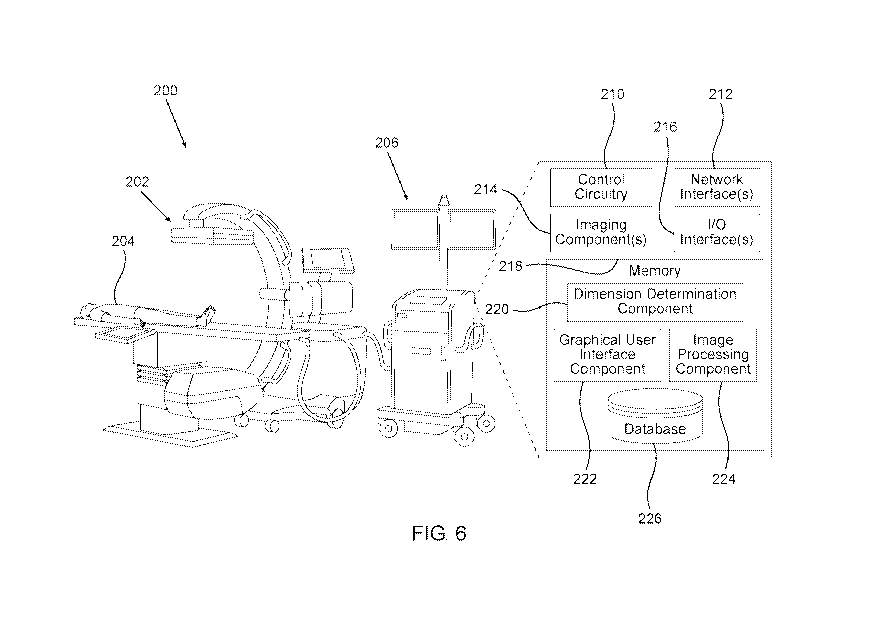
[00115] Reference is now made to Fig. 6, illustrating an example architecture
200 for
estimating valve diameters in real-time during valve expansion procedures,
based on an
analysis of one or more images acquired during valve expansion at the site of
implantation.
The architecture 200 includes one or more imaging devices 202 (referred to as
"the imaging
device 202", for ease of discussion) configured to capture/generate one or
more images of the
prosthetic valve 100 during implantation within a patient 204, and one or more
computing
systems 206 (referred to as "the computing system 206", for ease of
discussion) configured to
evaluate one or more images to estimate at least one diameter of the
prosthetic valve 100. In
some examples, an indication of the estimated at least one diameter is output.
As will be
described below, the indication of the estimated at least diameter can
include: one or more
estimated diameters, optionally in SI measurements; and/or an axial profile of
the prosthetic
valve. The imaging device 202 and the computing system 206 can be configured
to
communicate via wired or wireless communication appliances, such as to
send/receive data
including one or more images created by the imaging device 202 and/or other
data. The
computing system 206 can be configured to receive input from and/or provide
output to a user,
such as a physician, a technician, a radiologist, and so on. In some examples,
the imaging
device 202 and the computing system 206 are located at the same
facility/environment/location.
[00116] The imaging device 202 can be implemented as one or more x-ray
devices,
ultrasound devices, and/or other types of medical imaging devices. The imaging
device 202
can generally be configured to capture/generate one or more images including
visual
representations of interior anatomy, such as of the organs/tissues/other
anatomical features of
a patient, and prosthetic devices positioned within the patient's body, such
as stents, prosthetic
valves and the like. According to some examples, the imaging device 202 is a
fluoroscopic
imaging device. A fluoroscopy device, as shown in the example illustrated in
Fig. 6, can include
a fluoroscopy source and a fluoroscopy detector. In some examples, the
architecture 200
comprises a fluoroscopy device 202 and a monitor 216. The fluoroscopy source
can be
21 -
CA 03199434 2023-04-24
WO 2022/093896 PCT/US2021/056756
positioned over patient 204 so as to obtain a left anterior oblique (LAO)
projection of between
30 and 45, such as between 30 and 40, degrees with a 30-degree cranial tilt
(for orthogonal
projection of the aortic annulus). In some examples, the imaging device 202
includes more than
one device, such as a fluoroscopy device used in combination with an
ultrasound probe (not
shown) for imaging enhancement.
[00117] The computing system 206 can be implemented as one or more computing
devices,
such as one or more desktop computers, laptops computers, servers,
smartphones, electronic
reader devices, mobile handsets, personal digital assistants, portable
navigation devices,
portable gaming devices, tablet computers, wearable devices (e.g., a watch,
optical head-
mounted display, etc.), portable media players, televisions, set-top boxes,
computer systems in
a vehicle, appliances, cameras, security systems, home-based computer systems,
projectors,
medical monitors, and so on. In some examples, the one or more computing
devices are
configured in a cluster, data center, cloud computing environment, or a
combination thereof.
In some examples, the one or more computing devices are implemented as local
resources that
are located locally at an environment of the imaging device 202.
[00118] As illustrated, the computing system 206 can include one or more of
the following
components, devices, modules, and/or units (referred to herein as
"components"), either
separately/individually and/or in combination/collectively: control circuitry
210, one or more
network interfaces 212, one or more imaging components 214, one or more I/0
interfaces 216,
and/or memory 218. Although certain components of the computing system 206 are
illustrated
in Figure 6, it should be understood that additional components not shown can
be included in
examples in accordance with the present disclosure. Furthermore, certain of
the illustrated
components can be omitted in some examples.
[00119] Although the control circuitry 210 is illustrated as a separate
component in the
diagram of Figure 6, it should be understood that any or all of the remaining
components of the
computing system 206 can be embodied at least in part in the control circuitry
210. That is, the
control circuitry 210 can include various devices (active and/or passive),
semiconductor
materials and/or areas, layers, regions, and/or portions thereof, conductors,
leads, vias,
connections, and/or the like, wherein one or more of the other components of
the computing
system 206 and/or portion(s) thereof can be formed and/or embodied at least in
part in/by such
circuitry components/devices. Specifically, any discussion of steps that are
performed
dimension determination component 220, which is illustrated as a component of
memory 218
22 -
CA 03199434 2023-04-24
WO 2022/093896 PCT/US2021/056756
in Fig. 6 and shown separately from control circuitry 210, may actually be
performed by control
circuitry 210, wherein any of the memory 218 and/or the dimension
determination component
220 can be embodied within the control circuitry 210. Moreover, in some
examples, dimension
determination component 220 is embodied as a set of instructions (e.g.,
software commands
and algorithms) that are performed by a processor of the control circuitry
210.
[00120] The various components of the computing system 206 can be electrically
and/or
communicatively coupled using certain connectivity circuitry/devices/features,
which may or
may not be part of the control circuitry 210. For example, the connectivity
feature(s) can
include one or more printed circuit boards configured to facilitate mounting
and/or
interconnectivity of at least some of the various components/circuitry of the
computing system
206. In some examples, one or more control circuitry 210, the one or more
network interfaces
212, the one or more imaging components 214, the one or more I/0 interfaces
216, and/or the
database/memory 218, can be electrically and/or communicatively coupled to
each other.
[00121] The one or more network interfaces 212 can be configured to
communicate with
one or more devices/systems over one or more networks. For example, the one or
more network
interfaces 212 can send/receive data in a wireless and/or wired manner over a
network, such as
one or more images captured by the imaging device 202. The networks can
include various
communication protocols, such as local area networks (LAN), wide area networks
(WAN)
(e.g., the Internet), personal area networks (PAN), body area networks (BAN),
etc. In some
examples, the one or more network interfaces 212 can implement a wireless
technology such
as Bluetooth, Wi-Fi, near field communication (NFC), or the like.
[00122] The one or more imaging components 214 can include generators,
sensors,
detectors, cameras, etc. configured to provide/generate signals/radiation
and/or to
receive/detect signals/radiation, which can be used to capture/generate one or
more images.
While shown schematically as part of the computing system 206, which may
communicate
with the imaging device 202, it is to be understood that the one or more
imaging components
214 can be included within the imaging device 202, and that the computing
system 206 can be,
in some examples, a control system of the imaging device 202 which is
interconnected with
other components of the imaging device 202.
[00123] The one or more I/0 components 216 can include a variety of components
to receive
input and/or provide output, such as to interface with a user. The one or more
I/0 components
23 -
CA 03199434 2023-04-24
WO 2022/093896 PCT/US2021/056756
216 can be configured to receive touch, speech, gesture, or any other type of
input. Further, the
one or more I/0 components 216 can be configured to output display data, audio
data, haptic
feedback data, or any other type of output data. The one or more I/0
components 216 can
include the one or more displays (sometimes referred to as "one or more
display devices"),
touchscreens, touch pads, controllers, mice, keyboards, wearable devices
(e.g., optical head-
mounted display), virtual or augmented reality devices (e.g., head-mounted
display), speakers
(e.g., configured to output sounds based on audio signals), microphones (e.g.,
configured to
receive sounds and generate audio signals), cameras, and so on. The one or
more displays can
include one or more liquid-crystal displays (LCD), light-emitting diode (LED)
displays,
organic LED displays, plasma displays, electronic paper displays, and/or any
other type(s) of
technology. In some examples, the one or more displays include one or more
touchscreens
configured to receive input and/or display data.
[00124] As illustrated, the memory 218 can include a dimension determination
component
220, a graphical user interface component 222, and/or image processing
component 224
configured to facilitate various functionality discussed herein. In some
examples, one or more
of the components 220-224 can include and/or be implemented as one or more
executable
instructions that, when executed by the control circuitry 210, cause the
control circuitry 210 to
perform one or more operations. Although many examples are discussed in the
context of the
components 220-224 including one or more instructions that are executable by
the control
circuitry 210, any of the components 220-224 can be implemented at least in
part as one or
more hardware logic components, such as one or more application specific
integrated circuits
(ASIC), one or more field-programmable gate arrays (FPGAs), one or more
program-specific
standard products (ASSPs), one or more complex programmable logic devices
(CPLDs),
and/or the like. Furthermore, although the components 220-224 are illustrated
as being
included within the computing system 206, any of the components 220-224 can be
implemented at least in part within another device/system, such as the imaging
device 202 (e.g.,
a fluoroscopy device) and/or another device/system. Similarly, any of the
other components of
the computing system 206 can be implemented at least in part within another
device/system.
[00125] The dimension determination component 220 can be configured to
identify one or
more dimension of a prosthetic valve 100. The dimension determination
component 220 can
evaluate one or more images acquired by the imaging device 202. The evaluation
of the one or
more acquired images can determine one or more dimensions of a prosthetic
valve 100. A
24 -
CA 03199434 2023-04-24
WO 2022/093896 PCT/US2021/056756
dimension of prosthetic valve 100 can include a length of a component of the
prosthetic valve
100, a distance between features or components of the prosthetic valve 100, a
ratio between
lengths of components of the prosthetic valve 100, and/or an angle between
components of the
prosthetic valve 100. For example, a dimension of prosthetic valve 100 can
include a distance
between junctions 114 of the prosthetic valve 100, and/or an angle between
intersecting strut
segments 112. The dimension determination component 220 can store data
indicative of such
dimensions of the prosthetic valve 100 in a database 226.
[00126] In some examples, the dimension determination component 220 can
evaluate one
or more images acquired by the imaging device 202 (e.g., a fluoroscopy device)
to identify
structural components of the prosthetic valve 100 that are visible in the
acquired image/s, for
example, radiopaque structural components of the prosthetic valve 100, such as
struts 110 and
strut segments 112 thereof, junctions 114, pins 136 that may extend through
apertures 134, as
well as components of expansion and locking assemblies 138 such as outer
members 140.
[00127] In some examples, the dimension determination component 220 can
evaluate one
or more images acquired by the imaging device 202 (e.g., a fluoroscopy device)
to further
identify anatomical structures in the vicinity of the implanted prosthetic
valve 100, such as
walls surrounding a native annulus against which the prosthetic valve 100 is
implanted. Such
anatomical structures can include, for example, walls of the ascending aorta
12, the aortic
annulus 14, the cusps 16, and/or the LVOT 18 (shown, for example, in Fig. 7A).
[00128] In some examples, the dimension determination component 220 can
evaluate
multiple images from different orientations/positions/angles. For example, the
dimension
determination component 220 can identify one or more dimensions and/or
positions of
structural components of the prosthetic valve 100 by analyzing a first image
from a first
orientation/position within a patient and analyzing a second image from a
second
orientation/position within the patient. In some examples, a position of a
structural component
of the prosthetic valve 100 can include one or more coordinates of the
structural component
within a coordinate system/space.
[00129] In some examples, one or more dimensions and/or positions of
structural
components of the prosthetic valve 100 can include a dimensions/position of a
visual
representation of the structural components of the prosthetic valve 100 and/or
dimension of the
prosthetic valve 100 in an image, such as a size/length/distance of the visual
representation, a
25 -
CA 03199434 2023-04-24
WO 2022/093896 PCT/US2021/056756
color/shading of the visual representation, a position of the visual
representation within the
image, and so on.
[00130] In some examples, the dimension determination component 220 operates
in
cooperation with the graphical user interface component 222. For example, the
graphical user
interface component 222 can be configured to provide an interface that
includes an image. A
user, such as a physician or technician, can view the image and provide input
regarding a
dimension of the prosthetic valve 100 or position of a structural component of
the prosthetic
valve 100. In one example, the user can designate a representation in an image
as representing
a particular structural component, such as strut segment 112, an outer member
140, etc. In
another example, a user can designate a first point/location on an image and a
second
point/location in the image and provide input requesting that a distance be
calculated between
the first point/location and the second point/location. The user can also
provide input to label
the distance. In examples, a user can provide input to determine/label any of
the dimensions of
the prosthetic valve 100. In examples, the dimension determination component
220 can use
input provided by a user to evaluate one or more images and/or store data
regarding one or
more characteristics/positions of one or more dimensions of the prosthetic
valve 100 and/or
positions of a structural components of the prosthetic valve 100 in the
database 226.
[00131] Further, in some examples, the dimension determination component 220
operates
in cooperation with the image processing component 224 to evaluate an image.
For example,
the image processing component 224 can perform one or more image processing
techniques
with one or more images to automatically identify image-based features within
the one or more
images and/or classify the one or more image-based features as structural
components of the
prosthetic valve 100. In some examples, the image processing component 224
uses one or more
intelligence techniques, such as one or more machine-trained models, to
analyze one or more
images. In examples, the dimension determination component 220 can use
information
determined by the image processing component 224 to evaluate one or more
images and/or
store data regarding one or more characteristics/positions of one or more
dimensions of the
prosthetic valve 100 and/or positions of a structural components of the
prosthetic valve 100 in
the database 226.
[00132] Data/information generated/determined herein can be used in a variety
of manners.
In some examples, data regarding one or more dimensions of the prosthetic
valve 100 can be
used to provide real-time estimates of valve expansion diameter at various
regions of the
26 -
CA 03199434 2023-04-24
WO 2022/093896 PCT/US2021/056756
prosthetic valve 100, which in turn can be used to generate
instructions/information, such as
whether the prosthetic valve 100 should be further expanded, whether an
expansion procedure
should be halted, or whether re-compressions of the prosthetic valve 100 may
be required. In
examples, such information can be displayed to a user via a user interface.
[00133] As noted above, the database 226 can store one or more images acquired
by the
imaging device 202, as well as store data regarding dimensions of the
prosthetic valve 100
and/or positions of a structural components of the prosthetic valve 100, as
well as estimated
expansion diameters and optional generated instructions/information. Although
the database
226 is illustrated as being included within the computing system 206, in some
examples, the
database 226 can be implemented elsewhere, such as within a remote resource.
[00134] The term "control circuitry" is used herein according to its broad and
ordinary
meaning, and can refer to any collection of one or more processors, processing
circuitry,
processing modules/units, chips, dies (e.g., semiconductor dies including come
or more active
and/or passive devices and/or connectivity circuitry), microprocessors, micro-
controllers,
digital signal processors, microcomputers, central processing units, graphics
processing units,
field programmable gate arrays, programmable logic devices, state machines
(e.g., hardware
state machines), logic circuitry, analog circuitry, digital circuitry, and/or
any device that
manipulates signals (analog and/or digital) based on hard coding of the
circuitry and/or
operational instructions. Control circuitry can further comprise one or more,
storage devices,
which can be embodied in a single memory device, a plurality of memory
devices, and/or
embedded circuitry of a device. Such data storage can comprise read-only
memory, random
access memory, volatile memory, non-volatile memory, static memory, dynamic
memory,
flash memory, cache memory, data storage registers, and/or any device that
stores digital
information. It should be noted that in examples in which control circuitry
comprises a
hardware state machine (and/or implements a software state machine), analog
circuitry, digital
circuitry, and/or logic circuitry, data storage device(s)/register(s) storing
any associated
operational instructions can be embedded within, or external to, the circuitry
comprising the
state machine, analog circuitry, digital circuitry, and/or logic circuitry.
[00135] The term "memory" is used herein according to its broad and ordinary
meaning and
can refer to any suitable or desirable type of computer-readable media. For
example, computer-
readable media can include one or more volatile data storage devices, non-
volatile data storage
devices, removable data storage devices, and/or nonremovable data storage
devices
27 -
CA 03199434 2023-04-24
WO 2022/093896 PCT/US2021/056756
implemented using any technology, layout, and/or data structure(s)/protocol,
including any
suitable or desirable computer-readable instructions, data structures, program
modules, or other
types of data.
[00136] Computer-readable media that can be implemented in accordance with
examples of
the present disclosure includes, but is not limited to, phase change memory,
static random-
access memory (SRAM), dynamic random-access memory (DRAM), other types of
random
access memory (RAM), read-only memory (ROM), electrically erasable
programmable read-
only memory (EEPROM), flash memory or other memory technology, compact disk
read-only
memory (CD-ROM), digital versatile disks (DVD) or other optical storage,
magnetic cassettes,
magnetic tape, magnetic disk storage or other magnetic storage devices, or any
other non-
transitory medium that can be used to store information for access by a
computing device. As
used in certain contexts herein, computer-readable media may not generally
include
communication media, such as modulated data signals and carrier waves. As
such, computer-
readable media should generally be understood to refer to non-transitory
media.
[00137] Figs. 7A-7C illustrate views of examples of a prosthetic valve 100
(which may be
expanded against an aortic annulus 14 as shown in Fig. 7A), demonstrating
structural
components of the prosthetic valve 100 and dimensions of the prosthetic valve
100 that can be
identified and determined by the dimension determination component 220, based
on analyses
of images acquired by the imaging device 202 of the views shown in Figs. 7A-
7C.
[00138] The term "image", as used herein, is used for simplicity to refer to
either a single
acquired image or two or more acquired images.
[00139] In some examples, the techniques and systems discussed herein can
evaluate images
acquired during an implantation procedure of a prosthetic valve 100, and more
precisely, during
expansion of a prosthetic valve 100 within a desired site of implantation
within a patient's
body, to identify structural components of the prosthetic valve 100 such as
junctions 114, strut
segments 112, cells 108, cell columns 130, and outer members 140 of expansion
and locking
assemblies 138, and potentially structural elements of the anatomy surrounding
the prosthetic
valve at the site of implantation, such as the aortic walls 12, aortic annulus
14, cusps 16, and
the LVOT 18. Based on identifying structural components of the prosthetic
valve 100 that are
visible/represented in the image, the techniques and systems can determine
dimensions of the
28 -
CA 03199434 2023-04-24
WO 2022/093896 PCT/US2021/056756
prosthetic valve 100, evaluate valve expansion diameters based on such
dimensions, and
provide instructions/information based thereon.
[00140] Fig. 7A shows some example dimensions that can be determined from the
acquired
image, including lateral distances W between junctions 114. In some examples,
a process for
estimating at least one expansion diameter of the prosthetic valve includes
determining at least
one, and optionally a plurality of, lateral distances W between junctions 114
along a non-apical
cell column 130, such as lateral distances W 1 , W2, W3 and W4 shown in Fig.
7A.
[00141] The process can include identification of structural components
required to identify
a non-apical column, such as non-apical cell column 130d shown in Fig. 7A,
bound between
apical cell columns 130c and 130e. Identification of cell columns 130 can
begin by
identification of strut segments 112 and/or junctions 114 that may be included
in such cells.
Once junctions 114 are identified within an acquired image, such junctions may
be classified
as non-apical junctions 120 or as apical junctions such as outflow apices 116
and/or inflow
apices 118.
[00142] In some examples, identifications of the types of junctions 114 can be
based solely
on their positions relative to each other, and classification as apical and
non-apical cell columns
130 can be based solely on junctions 114 included in each column. In some
examples, the
process further includes identification of strut segments 112 extending
between junctions 114.
Junctions 114 can be identified either by identifying apertures 134, pins 136,
and/or
intersections between strut segments 112. In some examples, the position of
intersecting strut
segments 112 can be utilized to classify the junctions 114 to non-apical
junctions 120, outflow
apices 116, and/or inflow apices 118.
[00143] In some examples, the process further includes identifying closed
cells 108 and
open cells 109, based on identified intersecting strut segments 112 and/or
junctions 114 of the
cells, wherein closed cells 108 will include four junctions 114 and four
intersecting struts
segments 112, while open cells 109 will include three junctions 114 and two
strut segments
112, wherein one of the three junctions is a non-apical junctions, and the
additional two
junctions are outflow apices 116 or inflow apices 118.
[00144] The process can further include determinations of at least one lateral
distance W
along different axial positions of the non-apical cell column 130d, such as
lateral distance W1
between junctions 114(1,1) and 114(1,2), which are outflow apices 116, lateral
distance W2
29 -
CA 03199434 2023-04-24
WO 2022/093896 PCT/US2021/056756
between junctions 114(2,1) and 114(2,2), lateral distance W3 between junctions
114(3,1) and
114(3,2), and lateral distance W4 between junctions 114(4,1) and 114(4,2),
which are inflow
apices 118. The plurality of lateral distances W1-W4 are substantially
parallel to each other, as
shown.
[00145] The lateral distance W can be determined between two consecutive
junctions at
opposite lateral ends of a closed cell 108, such as lateral distances W2 and
W3 shown in Fig.
7, or between two consecutive apices 116, 118, such as lateral distance W1
disposed at the
outflow end 102 of the valve, or lateral distance W4 disposed at the inflow
end 104 of the
valve.
[00146] Dimensions such as lateral distances W (e.g., W1-W4) may be measured
in pixels.
In some examples, there is provided at least one constant-length structural
component of the
prosthetic valve 100, defined as a structural component that does not vary in
length throughout
the implantation procedure, and wherein the length of this component is known
and can serve
as a scale reference utilized to calibrate other dimensions and convert pixels
to SI units, for
example. In some examples, a component of the expansion and locking assembly
138, such as
an outer member 140, can serve as a constant-length structural component,
having a known
constant outer member length Lp as shown in Fig. 7A. Other types of prosthetic
valves can
include other constant-length structural components, such as a commis sure
post attached to the
frame or integrally formed therewith, having a vertical post length Lp. In
some examples, a
strut segment 112 can serve as a constant-length structural component, having
a strut segment
length Ls (see for example Fig. 7C).
[00147] Components that may serve as constant-length structural components are
rigid
components that do not deform and do not foreshorten or otherwise change in
length during
valve expansion, and that are identifiable in an acquired image, such as being
radiopaque (e.g.,
being made of a metallic material).
[00148] It is to be understood that other components of the prosthetic valve,
that need to be
identified in an acquired image, can also be preferably radiopaque, such as
struts 110 and
segments 112 thereof, or pins 136, or should otherwise be identifiable by
having borders that
are radiopaque, for example apertures 134 whose borders within the metallic
struts 110 can be
identifiable.
30 -
CA 03199434 2023-04-24
WO 2022/093896 PCT/US2021/056756
[00149] Estimation of an expansion diameter of the prosthetic valve 100 can be
based on at
least one lateral distance W. In some examples, a single lateral distance W is
determined. This
may be sufficient in cases in which the prosthetic valve 100 is expanded to a
cylindrical
configuration, having a uniform expansion diameter along its length. In such
cases, estimation
of an expansion diameter at any axial position along the prosthetic valve 100,
based on any
lateral distance W, may be indicative of the expansion diameter along any
other axial position
of the prosthetic valve.
[00150] In some examples, at least two lateral distances W are determined at
different axial
locations along the prosthetic valve 100. A plurality of lateral distances W
may be required for
estimation expansion diameters at different axial positions of the prosthetic
valve 100, for
prosthetic valves that expand to a non-cylindrical configuration, such as the
frustoconical
configuration described hereinabove in conjunction with Figs. 5A-5C. A lateral
distance W
measured between two junctions 114 at each axial position along the prosthetic
valve 100 may
be utilized for estimation of the expansion diameter at that axial position,
such that two lateral
distances W at different axial positions may be utilized for estimation of
expansion diameter
along other axial positions of the prosthetic valve 100 for example by means
of mathematical
interpolations or extrapolations. More than two lateral inter-junctions
distance W may be
determined in order to improve accuracy of the interpolation of extrapolation
along other axial
regions of the prosthetic valve 100.
[00151] The term "axial", as used herein, refers to a direction extending
between the inflow
end 104 and the outflow end 102 (which may be also referred to as a height of
the valve).
Reference to different axial positions refers to different heights along the
prosthetic valve 100,
between the inflow end 104 and the outflow end 102.
[00152] The inflow end 104 can define an inflow plane, passing through all
inflow apices
118, and the outflow end 102 can similarly define an outflow plane, passing
through all outflow
apices 116. A plurality of lateral planes can be defined between the inflow
plane and the
outflow plane, parallel to each other and to the inflow and outflow planes.
Any reference to a
lateral plane refers to a plane between the inflow and outflow planes, that is
parallel thereto.
[00153] Each lateral width W is defined along such lateral plane, wherein an
expansion
diameter of the prosthetic valve at the height (or axial position) of the same
lateral plane can
be estimated from the lateral width W. Thus, lateral width W1 can be utilized
for estimation of
31 -
CA 03199434 2023-04-24
WO 2022/093896 PCT/US2021/056756
an expansion diameter at the outflow plane, also referred to as the outflow
diameter Do. Lateral
width W4 can be utilized for estimation of an expansion diameter at the inflow
plane, also
referred to as the inflow diameter Di. Lateral width W2 can be utilized for
estimation of an
expansion diameter at the height of the lateral plane passing through
junctions 114(2,1) and
114(2,2), and lateral width W3 can be utilized for estimation of an expansion
diameter at the
height of the lateral plane passing through junctions 114(3,1) and 114(3,2).
[00154] In the case of a prosthetic valve expanded to a frustoconical shape,
having a non-
uniform diameter, each lateral width at a different axial position can have a
different
magnitude. For example, W4 <W3 <W2 < W1 as shown in Fig. 7A.
[00155] Fig. 7B shows additional example dimensions that can be determined
from the
acquired image, including vertical heights H and lateral distances W between
junctions 114. In
some examples, a process for estimating at least one expansion diameter of the
prosthetic valve
includes determining at least one, and optionally a plurality of, lateral
distances W and/or
vertical heights H between junctions 114 along an apical cell column 130, such
as lateral
distances W5, W6, W7 and vertical heights H1 and Hio shown in Fig. 7B.
[00156] The process can include identification of structural components
required to identify
an apical column, such as apical cell column 130e shown in Fig. 7B, bound
between non-apical
cell columns 130d and 130f. Identification of struts segments 112 and cell
columns 130, as
well as identification and classification of junctions 114, can be performed
in the same manner
described above with respect to identification of non-apical columns.
[00157] The process can further include determinations of at least one lateral
distance W
along different axial positions of the apical cell column 130e, such as
lateral distance W5
between junctions 114(5,1) and 114(5,2), which are non-apical proximal-most
junctions 120a,
lateral distance W6 between junctions 114(6,1) and 114(6,2), and lateral
distance W7 between
junctions 114(7,1) and 114(7,2), which are non-apical distal-most junctions
120c.
[00158] The plurality of lateral distances W5-W7 are substantially parallel to
each other, as
shown. Lateral width W5 can be utilized for estimation of an expansion
diameter at the lateral
plane passing through junctions 114(5,1) and 114(5,2). Lateral width W6 can be
utilized for
estimation of an expansion diameter at the lateral plane passing through
junctions 114(6,1) and
114(6,2). Lateral width W7 can be utilized for estimation of an expansion
diameter at the lateral
plane passing through junctions 114(7,1) and 114(7,2). In the case of a
prosthetic valve
32 -
CA 03199434 2023-04-24
WO 2022/093896 PCT/US2021/056756
expanded to a frustoconical shape, having a non-uniform diameter, each lateral
width at a
different axial position can have a different magnitude. For example, W7 <W6
<W5 as shown
in Fig. 7B.
[00159] In some examples, lateral widths W can be determined along more than
one cell
column 130. For example, at least some of lateral widths W 1 -W4 can be
determined between
junctions 114 disposed at opposite lateral ends of intersecting strut segments
112 of a non-
apical cell column 130d, and at least some of lateral widths W5-W7 can be
determined between
junctions 114 disposed at opposite lateral ends of intersecting strut segments
112 of a apical
cell column 130e. Since lateral widths W 1 -W4 and lateral widths W5-W7 are
positioned at
different axial positions, such as lateral width W5 along a lateral plane
positioned between the
lateral planes of lateral widths W1 and W2, and lateral width W2 along a
lateral plane
positioned between the lateral planes of lateral widths W5 and W6, and so on,
identifying
lateral widths from adjacent apical and non-apical cell columns can enhance
the resolution of
the number of diameters estimated at different axial positions of the valve,
thereby improving
accuracy of interpolations or extrapolations performed to estimate an
expansion diameter value
at an axial position that does not cross through specific lateral junction 114
or identified lateral
widths W.
[00160] According to some examples, the dimensions determined from the
acquired image
can include vertical heights between two junctions 114 aligned along a
vertical line. For
example, Fig. 7B shows an example of a height H1 between two junctions 114 of
the cell that
includes lateral width W7. Thus, lateral width W7 and vertical height H1 can
together provide
the width and height of the call through which they extend.
[00161] While H1 shows an example of a vertical height H1 extending between
opposite
vertical junctions of a single cell 108, other vertical heights H can be
determined between
opposite vertical junctions of more than one cells. For example, Hio shown in
Fig. 7B spans
across three cells vertically aligned with each other, and more specifically,
extends between an
inflow apex 118 and an outflow apex 116 vertically aligned therewith, thereby
representing the
vertical height of the entire frame 106 between the inflow end 104 and the
outflow end 102.
Other heights may span across more than one cell but less than the entire
height of the frame.
[00162] In the case of a prosthetic valve expanded to a frustoconical shape,
having a non-
uniform diameter, cells at different axial positions along the same cell
column may have
33 -
CA 03199434 2023-04-24
WO 2022/093896 PCT/US2021/056756
different vertical heights, as shown for example in Fig. 7B, wherein H1 is
longer than the
vertical heights of cells vertically aligned therewith, at axial positions
that are proximal thereto.
[00163] While shown in the example of Fig. 7B to be determined between
junctions of an
apical column, such as cell column 130e, it is to be understood that vertical
heights can be
similarly determined between junctions of a non-apical cell column, such as
cell column 130d.
In some examples, determination of dimensions from an acquired image can
include at least
one lateral width, at least one vertical height, and/or combinations thereof.
Vertical heights
may be determined for estimation of frame foreshortening during expansion
thereof. Frame
foreshortening can be used to derive expansion diameters based on known
relation between
axial foreshortening and radial expansion, and thus may serve as an additional
method used for
estimation of expansion diameter that can be used in combination with lateral-
width based
estimates, so as to improve accuracy of the estimated diameter.
[00164] In some examples, two or more vertical height H determined along two
or more cell
columns 130, thereby representing vertical heights H at different lateral
positions across the
circumference of the prosthetic valve, may be indicative of whether the valve
is expanded in
an even or an un-even manner along its circumference, and the extent of un-
evenness at
different circumferential positions during expansion thereof.
[00165] Fig. 7C shows additional example dimensions that can be determined
from the
acquired image, including strut opening angles a, (3, y, and lateral distances
W between
junctions 114 that can be derived therefrom. An opening angle can include a
vertically oriented
opening angle a defined at the intersection between two strut sections 112,
and oriented at a
vertical direction from the point of intersection. For example, Fig. 7C shows
a vertically
oriented opening angle al defined between strut sections 112c and 112f,
intersecting at a
junction 114 that can be identified by aperture 134(5).
[00166] A plurality of angles, such as al, a2 and a3 can be determined, for
example ¨ being
vertically aligned along the same cell column 130, such as cell column 130d
shown in Fig. 7C.
While vertically oriented opening angle al, a2 and a3 may be oriented
proximally, vertically
oriented opening angle 01, (32 and (33, which are corresponding alternate
angles facing the distal
direction, can be determined in a similar manner.
[00167] An opening angle can similarly include a laterally oriented opening
angle y, oriented
at a lateral direction from the point of intersection. In some cases, the
laterally oriented opening
34 -
CA 03199434 2023-04-24
WO 2022/093896 PCT/US2021/056756
angle y is defined at the intersection between two strut segments 112. For
example, y2 and y3
shown in Fig. 7C are defined between intersecting strut segments 112, and are
actually
consecutive and supplementary angles of a2 and a3 (or 131 and (32). Another
type of a laterally
oriented opening angle y can be defined between a strut segment 112 and a
lateral width W
intersecting therewith. For example, yl can be defined between strut section
112f and the lateral
width between apertures 134(1,1) and 134(1,2), which is actually W1 shown in
Fig. 7A
between the same junctions (and not annotated again in Fig. 7C to avoid
clutter). Thus, any of
y 1 or y4 shown in Fig. 7C can be about half the size of consecutive and
supplementary angles
of al and 133, respectively.
[00168] Determination of an opening angle from an acquired image, can be used
in
combination with a known strut section length Ls, to derive the appropriate
lateral width W
extending between the corresponding opposite lateral junctions 114. If the
junctions 114 are
identified by their apertures 134, as shown in Fig. 7C for example, a strut
segment length Ls
may be defined as the length between the apertures 134 at both ends of the
strut segment 112.
This length Ls can be slightly angled with respect to the edges of the strut
segment 112 for
cases in which the apertures 134 on both ends thereof are offset with respect
to each other, as
shown.
[00169] Thus, determination of al can be used in combination with the known
length Ls to
derive lateral width W1 between apertures 134(1,1) and 134(2,1). It is to be
understood that
any reference to dimensions determined relative to junctions 114 may be
similarly applicable
to the same dimensions being determined relative to apertures 134 or pins 136,
at similar
positions across the frame 106, if apertures 134 or pins 136 are detectable in
the acquired image
and are utilized to identify the spatial positions of the apertures 134.
[00170] Determination of opening angles such as angles a, 13, y may be
advantageous since
the angles may serve as non-dimensional measures utilized for estimation of
various distances,
such as lateral lengths W and/or vertical heights H, without measuring such
distances as amount
of pixels that are later calibrated to lengths in SI units, for example.
Nevertheless, in some
examples, both direct determination of distances such as lateral widths W
and/or vertical
heights H, and determination of opening angles from which some of these
distances can be
derived, are performed, for example to improve accuracy of the process of
assessment.
35 -
CA 03199434 2023-04-24
WO 2022/093896 PCT/US2021/056756
[00171] Advantageously, the proposed methods do not rely on pre-measured
relations
between dimensions, such as opening angles or distances, and expansion
diameters of the
valve, and do not compare dimensions determined from the acquired images with
tables or
graphs storing such relations.
[00172] Fig. 8 shows a lateral cross-section of a prosthetic valve 100 across
a selected lateral
plane between the inflow end and the outflow end. As mentioned above, a
prosthetic valve 100
can include two layers of struts 110 intersecting with each other, including
inner struts 110i
and outer struts 1100, as shown. The junctions 114 can be identified the
apertures 134
extending therethrough (shown in the zoomed-in region of Fig. 8), or pins 136
extending
through such apertures (pins not illustrated in Fig. 8 for clarity). As
further shown in Fig. 8,
each aperture 134 can extend through a portion of a corresponding inner strut
110i, such that
the lateral widths W discussed hereinabove, are actually measured between
apertures 134
extending through the inner struts 110i.
[00173] As further shown in Fig. 8, the plurality of apertures 134 defined
across the
circumference of the frame 106 along a single lateral plane can define an
internal polygon Pi,
that includes a plurality of edges, each having a polygon edge length Le. The
estimated lateral
width W, determined at the level of the lateral plane shown in Fig. 8, serves
as the length of
each edge of the internal polygon Pi. Thus, the internal polygon Pi can be
derived from the
lateral width W determined at the level of the corresponding lateral plane,
multiplied by the
number of edges, which is equal to the number of junctions 114 disposed around
the
circumference of the valve at the corresponding lateral plane.
[00174] The outer diameter of the valve can be defined for a circumcircle
extending over
the outer surface defined by the outer struts 110o, illustrated as a dotted
circumcircle
circumscribing the outer struts 1100 in Fig. 8. The vertices of the internal
polygon Pi are
internally offset from the outer circumcircle by the thickness Th of the frame
at the junctions
114, between the inner surface of the inner strut 110i and the outer surface
of the outer strut
1100. The thickness Th may include the thickness of the inner strut 110i and
the thickness of
the outer strut 110o. In some examples, the frame 106 includes a washer 132
situated between
the inner strut 110i and the outer strut 1100 at each junction 114, such that
the thickness Th
includes the thickness of the washer 132 as well. In some examples, the pin
136 or other type
of fastener extending through the aperture 134 can include a head that extends
radially outward
beyond the outer surface of the outer strut 1100 (not shown in Fig. 8), such
that the thickness
36 -
CA 03199434 2023-04-24
WO 2022/093896 PCT/US2021/056756
Th includes the additional portion of pin head, resulting in an overall
thickness Th extending
between the inner surface of inner strut 110i and outer surface of the head of
pin 136.
[00175] Thus, the process of estimating an outer diameter of the prosthetic
valve 100 can
include estimating the outer diameter, at a specific axial position, as the
diameter of a
circumcircle approximated around an internal polygon having edges equal in
length to the
lateral width determined for the same plane, wherein the circumcircle may be
offset from the
vertices of the internal polygon by a thickness Th of the junctions. In some
examples, the outer
diameter can be estimated by the equation:
[00176] Dc = NW L tual ¨ = + 2 = Th
Lpixels
[00177] wherein Dc is the desired estimated outer diameter of the prosthetic
valve at the
relevant lateral plane (i.e., at the relevant axial position), N is the number
of edges of the
internal polygon Pi, such that N times W is the perimeter of the internal
polygon Pi. Lactual is
the length of the constant outer member length, which is a pre-measured known
value that can
be the outer member length (or commissural post length) Lp, or a strut section
length Ls, and
Lpixels is the length measured in pixels from the acquired images, such that
the ratio of Lactual to
Lpixels serves as a calibration for the size of lateral width W that can be
determined in pixels
from the acquired image. The junction thickness Th, which can be at least as
great as the
combined thickness of the inner and outer struts 110i and 110o, respectively,
compensates for
the additional offset of the circumcircle from the vertices of the internal
polygon Pi.
[00178] The portion of the formula without the adding twice the thickness Th
may represent
the diameter of a circumcircle surrounding the internal polygon Pi and
extending along its
vertices, which is the inner diameter of the prosthetic valve 100 at the same
lateral plane. Thus,
both inner and outer diameters can be estimated by the above-mentioned
formula, without and
with the additional of the offsetting parameter 2Th.
[00179] It is to be understood that a reference to any diameter D, unless
stated otherwise, is
to an outer diameter Dc.
[00180] While Dc can be estimated at discrete axial positions along which
lateral widths W
can be determined, based on lateral junctions 114, an outer diameter of
interest may be desired
at an axial position that is not in level with specific junctions 114, in
which case the desired
37 -
CA 03199434 2023-04-24
WO 2022/093896 PCT/US2021/056756
outer diameter, one or more, can be interpolated or extrapolated from two or
more outer
diameter estimated at axial positions for which lateral widths have been
determined.
[00181] For example, Fig. 7A shows a prosthetic valve 100 expanded against an
aortic
annulus 14. The outer diameter of the valve at the annular level Da should not
exceed a maximal
value, that can be determined, for example, from pre-CT images for a specific
patient, so as to
reduce risk of annular rupture. In the example illustrated in Fig. 7A, the
annular outer diameter
Da is positioned at a level that does not coincide with specific junctions
114, shown in the
illustrated example to be positioned slightly above (i.e., proximal to) the
level of the non-apical
distal-most junctions 120c (annotated, for example, in Fig. 7B). If at least
one outer diameter
Dc is estimated at lateral planes on both sides of the annular level, such as
at the level of W3
and at the level of W4 (which may be the inflow outer diameter Di), the
annular outer diameter
Da can be interpolated therefrom. In at least two outer diameters Dc are
estimated at lateral
planes on one side of the annular level (either proximal or distal), such as
the levels of W2 and
W3, the annular outer diameter Da can be extrapolated therefrom.
[00182] In some examples, the techniques and systems discussed herein can use
one or more
algorithms to determine a distance/dimension associated with the prosthetic
valve 100, such as
an algorithm that converts a number of pixels or a distance between pixels in
an acquired image
to a distance/dimension of the prosthetic valve 100.
[00183] According to some examples, a single outer diameter Dc is estimated by
the control
circuitry 210 and/or the dimension determination component 220, and optionally
presented to
a user (e.g., a physician, a technician, a radiologist, etc.) for example via
at least one I/0
interface 216 (e.g., a display), and/or stored in a database 226, and/or
transmitted via at least
one network interface 212. A single outer diameter may be applicable, as
mentioned above,
for cases in which the prosthetic valve 100 is expanded to a cylindrical shape
having a uniform
diameter along its length, or in cases wherein the outer diameter of interest
is at a single axial
position, and while other outer diameters may be estimated for interpolation
or extrapolation
of the desired single outer diameter of interest, they may not be shown.
[00184] According to some examples, more than one outer diameter Do is
estimated by the
control circuitry 210 and/or the dimension determination component 220, and
optionally
presented to a user (e.g., a physician, a technician, a radiologist, etc.) for
example via at least
one I/0 interface 216 (e.g., a display), and/or stored in a database 226,
and/or transmitted via
38 -
CA 03199434 2023-04-24
WO 2022/093896 PCT/US2021/056756
at least one network interface 212. For example, several outer diameters, such
as the inflow
diameter Di, outflow diameter Do, annular diameter Da, and potentially
additional diameter at
additional axial positions, may be estimated and potentially presented to the
user.
[00185] A method of estimating at least one outer diameter of a prosthetic
valve can include
a series of steps, that may be performed during prosthetic valve expansion.
The method can
include a step of acquiring one or more images of the prosthetic valve during
a valve expansion
procedure by an imaging device 202, such as a fluoroscopy device which is
conventionally
utilized for imaging during prosthetic valve implantation procedures. The
control circuitry 210
can receive the one or more acquired images (e.g., fluoroscopy images) from
the imaging
device 202. The acquired image can include components of the prosthetic valve
100 that can
be radiopaque components, such as the frame 106 comprised of struts 110 and
segments 112
thereof, and optionally expansion and locking assemblies 138 that can be
attached to the frame
106.
[00186] The method further comprises a step of analyzing the acquired image to
identify
structural components of the prosthetic valve 100, which can be performed by
the control
circuitry 210, including by the dimension determination component 220 and/or
image
processing component 224 that can be embodied within control circuitry 210.
Identification of
structural components can include identification of basic components of the
prosthetic valve
100 and identification of complex structures of the prosthetic valve 100. For
example,
identification of basic components can include radiopaque components, such as
strut segments
112, outer members 140 of expansion and locking assemblies 138, and junctions
114. Junctions
114 can be identified as the intersection regions between struts 110, by
identifying the borders
of apertures 134 extending there-through, by identifying washers 132 disposed
between inner
and outer struts, and/or by identifying pins 136 or other fasteners extending
through the
junctions (e.g., through apertures 134).
[00187] Complex structures may be structures that are combined from, or
include, a plurality
of the basic identified components, and may include cells 108 (e.g., closed
cells) that are
combined from four strut segments 112 intersecting at four junctions 114, and
cell columns
130 that may include several cells 108 vertically aligned with each other. An
association
between a complex structure such as a cell 108 or a cell column 130 and the
basic components
comprised therein can be also identified, for example associating each strut
segment 112 with
the cells 108 and/or the cell columns 130 it's comprised in, and associating
each junction 114
39 -
CA 03199434 2023-04-24
WO 2022/093896 PCT/US2021/056756
with the strut segments 112, the cells 108 and/or the cell columns 130 it's
comprised in. Each
strut segment 112 can be shared by, and associated with, more than one cell
108 and more than
one cell column 130. Each junction 114 is associated with more than one strut
segment 112
(e.g., associated with two strut segment 112 in the case of an apex, or with
four strut segments
112 in the case of a non-apical junction), and may be shared by and associated
with more than
one cell 108 and more than one cell column 130.
[00188] In some examples, the step of analyzing the acquired image to identify
structural
components further includes classifying at least some of the basic identified
components and/or
the complex structures. In some examples, the step of classifying includes
classification of the
type of each identified junction 114, for example as an outflow apex 116, an
inflow apex 118,
or a non-apical junction 120. In some examples, the step of classifying
includes classification
of the type of each cell 108 as a closed cell or an open cell 109. In some
examples, the step of
classifying includes classification of the type of each cell column 130 as an
apical cell column
or a non-apical cell column.
[00189] In some examples, the step of analyzing the acquired image to identify
structural
components further includes identification of the spatial position of
identified components,
such as basic components, and more specifically such as the spatial position
of junctions 114,
and further identifying junctions that are laterally aligned with each other.
This step can further
identify junctions that are laterally aligned with each other and belong to
the same cell 108
and/or the same cell column 130.
[00190] In some examples, control circuitry 210, including dimension
determination
component 220 and/or image processing component 224 that may be embedded
therein, can
use one or more image processing techniques that can use one or more models,
such as
machine-trained model, user-trained model, or another model that has been
trained to identify
and classify features in acquired images.
[00191] In some examples, control circuitry 210 can provide a user interface
to a user and/or
receive input regarding one or more dimensions and/or structural components of
the prosthetic
valve, including positions and/or classifications thereof. For example, the
control circuitry 210
can generate user interface data representing a user interface that includes
an acquired image
and/or send the user interface data to a display device for display of the
user interface, including
the acquired image. A user can view the acquired image through the interface
and provide input
40 -
CA 03199434 2023-04-24
WO 2022/093896 PCT/US2021/056756
identifying positions of structural components, such as junctions 114, strut
segment 112, outer
member 140 and the like. A user can further classify specific structural
components, such as
the type of junction 114 and/or junctions that are laterally aligned with each
other.
[00192] In one example, a user can designate a first point/location on an
image, that can be
a first junction, and a second point/location on an image, that can be a
second laterally aligned
with the first junction, and request that a distance, which is a lateral width
W, be calculated
between the first junction and the second junction. The same can be performed
for vertically
aligned junctions for calculating a vertical height. Similarly, a user can
designate a first strut
segment (that may be, in some implementations, indicated by pointing at two
points/locations
through which the strut segment extends) and a second strut segment that is
intersecting
therewith, requesting that an opening angle be calculated between the first
strut segment and
the second strut segment.
[00193] The various steps described hereinabove for analyzing an acquired
image can be
performed in any order. For example, the order of execution can include
identification of basic
components of the prosthetic valve and classification thereof, wherein the
step of identification
of complex structures is performed after classification of at least some
components, wherein
the classification facilitates identification of some of the complex
structures. Classification may
then be performed again for the identified complex structures. In some cases,
identification of
the spatial position of basic components can be performed prior to
classification thereof,
wherein the spatial position facilitates such classification (for example,
classifying a junction
114 as an outflow apex 116, and inflow apex 118, a non-apical proximal most
junction 120a,
a non-apical distal-most junction 120c, other non-apical junction 120 and the
like).
[00194] Thus, the method further includes a step of determining at least one
dimension of
the prosthetic valve, performed by the control circuitry, and more
specifically, by a dimension
determination component that can be embedded therein or associated therewith.
The at least
one dimension will always include at least one lateral width W. In some
examples, several (i.e.,
two or more) lateral widths W are determined, each between two laterally
spaced junctions
114. In some examples, several lateral widths W are determined at different
axial positions of
the same cell column 130, that can be either an apical cell column or a non-
apical cell column.
In some examples, at least two lateral widths W of two different cell columns
130 are
determined. For example, one or more lateral widths W can be determined for a
first cell
column, which can be an apical cell column, and one or more additional lateral
widths can be
41 -
CA 03199434 2023-04-24
WO 2022/093896 PCT/US2021/056756
determined for a second cell column, which can be a non-apical cell column,
wherein both
apical and non-apical cell columns 130 can be adjacent cell columns, that may
share some of
the strut segment 112 and junctions 114.
[00195] The determination of the at least one lateral width W can be performed
by directly
estimating a distance between two laterally aligned junctions 114, that can be
positioned
opposite to each other along the same cell (a closed cell 108, or an open cell
109 in the case of
inflow or outflow apices), or by first determining an opening angle defined
either between
intersecting strut segments and facing the lateral width W, or defined between
a strut segment
and a lateral width, as described hereinabove.
[00196] In some examples, the step of determining at least one dimension
further includes
determining at least one vertical height H. In some examples, several vertical
heights H are
determined at different lateral positions of the prosthetic valve, in which
case the method can
further include a step of comparing between the different vertical heights H
to evaluate whether
the prosthetic valve is expanded in an even or non-even manner across its
circumference, and
if the expansion is non-even, provide information regarding the extent to
which the expansion
is non-even.
[00197] In some examples, the step of analyzing the image to identify
structural components
of the prosthetic valve includes identifying a constant-length structural
component, and the
method further includes a step of obtaining a pre-stored length of the
constant-length structural
component. For example, an outer member 140 of an expansion and locking
assembly 138, or
another type of a commissural post that is either attached to, or integrally
formed with, the
frame 106, can be identified as a constant-length structural component and
classified or tagged
as such. The length of the outer member 140 can be pre-stored, for example in
the memory 218
and any component thereof (such as database 226), and this pre-stored length
Lp of the outer
member 140 (or other commissure post) can be retrieved (e.g., from the memory)
by the control
circuitry 210, and associated with the identified outer member 140.
[00198] In another example, strut segment 112 can be identified as a constant-
length
structural component and classified or tagged as such. While strut segments
112 pivot about
junctions 114 during valve expansion, their length remain constant and may be
pre-store, for
example in the memory 218 and any component thereof (such as database 226),
and this pre-
stored length Ls of the strut segment 112 can be retrieved (e.g., from the
memory) by the control
42 -
CA 03199434 2023-04-24
WO 2022/093896 PCT/US2021/056756
circuitry 210, and associated with the identified strut segment 112 serving as
the constant-
length structural component.
[00199] The method further includes a step of estimating at least one outer
diameter of the
prosthetic valve, performed by the control circuitry, based on the at least
one lateral width W
determined at the level (i.e., at the axial position) of the estimated outer
diameter, and the
retrieved length associated with the identified constant-length structural
component. This
estimation can follow the above-mentioned formula described in conjunction
with Fig. 8
hereinabove, which is based on calculation of a diameter of a circumcircle
surrounding an
approximated internal polygon Pi comprising a known number of edges N, each
having a length
equal to the determined lateral width W. The number of edges N is constant and
is known for
a specific prosthetic valve type, and is equal to the number of junctions 114
surrounding the
frame 106 across the corresponding lateral plane. Fig. 8 shows a specific
example of an internal
polygon Pi having nine edges extending between nine junctions 114. The
retrieved length
associated with the constant-length structural component serve to convert
distances from pixels
to length units.
[00200] In some examples, the step of estimating at least one outer diameter
further is further
includes adding a product of the thickness Th of a junction 114 (as shown in
the formula
hereinabove, the product can be doubling the thickness Th), compensating for
the additional
radial offset of the circumcircle from the vertices of the internal polygon
Pi.
[00201] In some examples, the step of estimating at least one outer diameter
includes
estimated a plurality of outer diameters, each at a different axial position
along the length of
the prosthetic valve, and each based on a lateral width W determined at the
axial position of
the corresponding estimated outer diameter.
[00202] In some examples, the step of estimating at least one outer diameter
further includes
estimating at least one outer diameter at an axial position for which a
lateral width has not been
determined, by extrapolating or interpolating from at least two outer
diameters estimated from
lateral widths W determined at the axial positions thereof. In some examples,
at least one outer
diameter is extrapolated from at least two outer diameters estimated from
lateral widths W
determined at axial positions on one side thereof, such as proximal or distal
thereto. In some
examples, at least one outer diameter is interpolated from at least two outer
diameters estimated
43 -
CA 03199434 2023-04-24
WO 2022/093896 PCT/US2021/056756
from lateral widths W determined at axial positions on both sides thereof,
i.e., both proximal
and distal thereto.
[00203] In some examples, the at least one outer diameter includes the inflow
diameter Di
and/or the outflow diameter Do. In some examples, the at least one outer
diameter includes the
annular diameter Do.
[00204] Any of the steps of identifying a constant-length structural component
and
retrieving a pre-stored length of the constant-length structural component and
associating the
length with the identified constant-length structural component, can be
performed at any stage
prior to the step of estimating at least one outer diameter.
[00205] The above-mentioned steps can be repeated for several stages of valve
expansion,
so as to monitor the outer diameter of the valve at a desired axial position
(one or more), such
as the annular diameter, inflow/outflow diameters, and potentially additional
diameter in-
between.
[00206] In some examples, at least one diameter threshold can be pre-stored
for at least one
axial position of the prosthetic valve, for example in memory 218 or
components thereof (e.g.,
database 226), or may be manually input by the user via the user interface
provided by the
control circuitry 210. The threshold may be the maximal allowable expansion
diameter at the
level of the native annulus (e.g., the aortic annulus 14), and may be patient
specific. In some
examples, such thresholds can be derived from images acquired by imaging
devices, which are
not necessarily the imaging device 202 described for the method hereinabove,
prior to valve
implantation. This may include, for example, pre-CT performed prior to
prosthetic valve
implantation, from which the thresholds can be derived.
[00207] According to some examples, the at least one image acquired by the
imaging device
202 includes tissues of the anatomical region at the region of implantation,
from which the
aortic annulus 14 can be identified in a similar manner to that described for
identification of
structural elements of the prosthetic valve 100 hereinabove. In some examples,
the method
includes a step of identifying the borders of the native annulus 14 against
which the prosthetic
valve is to be expanded, and determining a distance between opposite walls of
the annulus 14,
indicative of the diameter of the native annulus 14, from which the threshold
for the annular
diameter Da of the prosthetic valve can be determined.
44 -
CA 03199434 2023-04-24
WO 2022/093896 PCT/US2021/056756
[00208] According to some examples, an estimated outer diameter is compared
with a
threshold retrieved (for example, by the control circuitry from the memory)
for the
corresponding axial position (e.g., the level of the annulus), and a warning
may be generated if
the estimated outer diameter exceeds the threshold.
[00209] Throughout the entire process, the control circuitry 210 can generate
graphic
interface data that can be relayed to a display device. The graphic interface
data can include
the acquired images, and/or any of the identified structural components,
determined dimensions
and/or estimated outer diameters, that can be either tagged or otherwise
graphically layered
over the acquired image, or presented separately therefrom, in any form
including textual
and/or graphical representations thereof.
[00210] An advantage conferred by the systems and the methods disclosed
herein, is that
they enable continuous real-time diameter monitoring during prosthetic valve
expansion,
thereby providing valuable feedback to the clinician with respect to the valve
expansion within
the native anatomy. This valuable information may assist in preventing, or at
least reducing,
potential trauma to a tissue (e.g., the annulus). The clinician can
continuously readjust the
diameter of the prosthetic valve 100 as necessary, until the prosthetic valve
100 is expanded to
a diameter that best fits the native annulus. For example, a diameter which is
sufficient to
anchor the prosthetic valve 100 in place against the surrounding tissue, with
little or no
paravalvular leakage, and without over-expanding the prosthetic valve 100 so
as to avoid, or
reduce the risk of, native annulus rupture.
[00211] Reference is now made to Figs. 9A ¨ 9C, describing measurements of a
different
type of prosthetic valve. Particularly, Fig. 9A shows a first partial view of
another example of
a mechanically expandable prosthetic valve 300 and Fig. 9B shows a second
partial view of
prosthetic valve 300, without soft components (such a skirt and a leaflet
assembly). Similar to
prosthetic valve 100, prosthetic valve 300 includes an annular frame 310 which
can be a unitary
lattice frame made of a set 320 of intersecting struts, defined between an
outflow end 302 and
an inflow end 304. As shown above in relation to prosthetic valve 100, a
leaflet assembly (not
shown), as well as an inner skirt and/or an outer skirt can be provided,
however in the interest
of brevity these components are not described.
[00212] Unlike prosthetic valve 100, which is representative of a mechanically
valve that
includes two layers of struts hinged to each other at their intersecting
junctions, the prosthetic
45 -
CA 03199434 2023-04-24
WO 2022/093896 PCT/US2021/056756
valve 300 is representative of another valve type that can be expanded
utilizing a mechanical
mechanism, having a unitary frame with a single layer of struts, as will be
described in greater
detail hereinbelow. In some examples, the prosthetic valve 300 can be radially
expanded by
maintaining the inflow end 304 at a fixed position while applying a force in
the axial direction
against the outflow end 302 toward the inflow end 304. Alternatively, the
prosthetic valve 300
can be expanded by applying an axial force against the inflow end 304 while
maintaining the
outflow end 302 at a fixed position, or by applying opposing axial forces to
the inflow and
outflow ends 304, 302, respectively. According to some examples, a delivery
apparatus (not
shown) is provided which can include a plurality of actuation assemblies,
configured to radially
expand and/or radially compress the prosthetic valve 300 when actuated.
[00213] As shown in Figs. 9A-B, the prosthetic valve 300 can include one or
more actuators
360 mounted to and equally spaced around the inner surface of the frame 310.
Each of the
actuators 360 can be configured to form a releasable connection with a
respective actuation
assembly of a delivery apparatus (not shown).
[00214] The set 320 of interconnected struts of frame 310 of the prosthetic
valve 300
illustrated in Figs. 9A-B comprises rungs of curved struts 325, 327, 329, 333,
and axial struts
or posts 334, 335, 336. The curved struts define a plurality of cells 338
extending
circumferentially around the frame 310. While only one side of the frame 310
is illustrated in
FIGs. 9A-B, it should be appreciated that the frame 310 forms an annular
structure having an
opposite side that is substantially identical to the portion shown. In the
illustrated embodiment,
the frame 310 comprises an outflow rung 324 of curved struts 325 defining the
outflow end
302; a first intermediate rung 326 of curved struts 327; an intermediate rung
328 of curved
struts 329; and an inflow rung 332 of curved struts 333 defining the inflow
end 304.
[00215] The cells 338 can include first cells 339 and second cells 340. Each
first cell 339
can have an axially-extending elliptical shape including outflow apex 356 and
inflow apex 358
disposed at the major vertices of the ellipse. Each first cell 339 can further
comprise a
respective second cell 340 disposed within the outer perimeter of the first
cell 339. The second
cell 340 can have a circumferentially-extending elliptical shape including a
proximal junction
341a and a distal junction 341b disposed at the minor vertices of the ellipse.
Each proximal
post 335 can extend between a respective outflow apex 356 and a respective
distal end 357.
Each distal post 336 can extend between a respective inflow apex 358 and a
respective proximal
end 359. While illustrated as elliptical, it is to be understood that any of
the cells 338 can have
46 -
CA 03199434 2023-04-24
WO 2022/093896 PCT/US2021/056756
any of various other shapes, for example, hexagonal, triangular, tear drop
shaped, rectangular,
square, square-oval, etc.
[00216] As mentioned, the frame 310 can comprise a plurality of axially-
extending struts or
posts, including a plurality of proximal posts 335 and distal posts 336. The
proximal posts 335
(shown as the upper posts in the illustrated example) can extend to the
outflow end 302, and
the distal posts 336 (shown as the lower posts in the illustrated example) can
extend to the
inflow end 304. Each proximal post 335 can be axially aligned with a
corresponding distal post
336 for a pair of proximal and distal posts. One or more pairs of proximal and
distal posts 335,
336 can be configured as actuators 360. The frame 310 can further comprise
additional axial
support posts 334 disposed between each pair of adjacent circumferentially
disposed first cells
339, and the actuators 360 can be disposed such that they extend through and
are coupled to
the apices 356, 358 and junctions 341a, 341b through the first and second
cells. The axial
support posts 334 can be coupled together via curved struts 325, 327, 329,
333.
[00217] Each first cell 339 is formed by two curved struts 325 of the valve
frame outflow
rung 324 and two curved struts 333 of the valve frame inflow rung 332. Each
curved strut 325
is coupled on one end to a proximal post 335 of an actuator 360 and on the
other end to an axial
support post 334. Each curved strut 333 is coupled on one end to a distal post
336 of an actuator
360 and on the other end to an axial support post 334.
[00218] Each second cell 340 is formed by two curved struts 327 of the valve
frame first
intermediate rung 326 and two curved struts 329 of the valve frame second
intermediate rung
328. The lower/distal ends of the curved struts 327 and the upper/proximal
ends of the curved
struts 329 can be connected to the axial support posts 334. The upper/proximal
ends of the
curved struts 327 can be connected to a proximal post 335 of a respective
actuator 360. The
lower/distal ends of the curved struts 329 can be connected to a distal post
336 of the respective
actuator 360.
[00219] Each proximal post 335 can extend through and be coupled to outflow
apex 356
and proximal junction 341a of a respective first and second cell pair. Each
distal post 336 can
extend through and be coupled to inflow apex 358 and distal junction 341b of
the respective
first and second cell pair. In the illustrated embodiment, the frame 310
comprises six first cells
339 extending circumferentially in a row, with a second cell 340 within each
first cell 339, and
six pairs of proximal and distal posts 335, 336 coupled to a respective pair
of cells 339, 340.
47 -
CA 03199434 2023-04-24
WO 2022/093896 PCT/US2021/056756
However, in other embodiments, the frame 310 can comprise a greater or fewer
number of first
cells 339 within a row, and a correspondingly greater or fewer number of
second cells 340
and/or pairs of posts 335, 336.
[00220] In some embodiments, each pair of posts 335, 336 can be configured as
an actuator
360. For example, in the illustrated embodiment, each of the six pairs of
posts 335, 336 is
configured as an actuator 360. In other embodiments, not all pairs of posts
335, 336 need be
actuators. Where a pair of posts 335, 336 is configured as an actuator, a
threaded rod 362
extends through each post of 339, 340 of the pair to effect radial compression
and expansion
of the frame 310. The distal post 336 can comprise a threaded nut 364 disposed
at a proximal
end portion thereof and configured to engage the threaded rod 362. Rotation of
the threaded
rod 362 in a first direction (e.g., clockwise) can cause corresponding axial
movement of the
proximal and distal posts 335, 336 toward one another, expanding the frame
310, and rotation
of the threaded rod 362 in a second direction (e.g., counterclockwise) causes
corresponding
axial movement of the proximal and distal posts 335, 336 away from one
another, compressing
the frame. As the frame 310 moves from a compressed state to an expanded
state, the gap
between the proximal and distal posts 335, 336 can narrow.
[00221] Because the threaded rod 362 is secured to the frame 310 at axially
spaced locations
(e.g., the outflow end 302 and the inflow end 304) rotating the threaded rod
362 causes axial
movement of the outflow end 302 and inflow end 304 relative to one another to
cause radial
expansion or compression of the frame 310. For example, moving the outflow and
inflow ends
302, 304 toward one another causes the frame 310 to foreshorten axially and
expand radially.
[00222] As shown in Figs. 9A-B, the axial support posts 334 can extend
longitudinally and
can include commissure support member, such as commissure windows 322, at a
respective
portion thereof. Although commissure window 322 is illustrated as being in a
proximal portion
of axial support post 334, this is not meant to be limiting in any way, and in
other examples,
commissure window 322 can be located at a different portion of the respective
axial support
post 334. According to some examples, one or more of the axial support posts
334 can extend
towards inflow end 304 via an extension member 345. In some examples, each
extension
member 345 culminates in an eyelet 346. The term "eyelet", as used herein,
means a small
structure exhibiting a hole. In one illustrated example, each eyelet 346 is
generally circular,
however this is not meant to be limiting in any way, and each eyelet 346 can
exhibit any shape.
48 -
CA 03199434 2023-04-24
WO 2022/093896 PCT/US2021/056756
[00223] Frame 310 can further have one or more pairs of eyelets 365. In one
illustrated
example, eyelets 365 are generally circular, however this is not meant to be
limiting in any
way, and each eyelet 346 can exhibit any shape. In some examples, eyelets 365
can be utilized
to secure an outer skirt (not shown). In some examples, eyelets 365 are each
positioned on a
respective valve frame inflow rung 332. In some examples, six eyelets 365 are
provided,
however this is not meant to be limiting in any way. In some examples, a pair
of eyelets 365
are associated with each commissure window 322, such that each pair of eyelets
365 are
positioned on opposing sides a respective commissure window 322. Although
Figs. 9A-B show
eyelets 365 on valve frame inflow rungs 332, this is not meant to be limiting
in any way, and
eyelets can be provided on valve frame outflow rung 324, in addition to, or
instead of, the
eyelets 365 on valve frame inflow rungs 332.
[00224] As mentioned, Figs. 9A-B show only one side of the frame 310. Though
only one
axial support post 334 comprising a commissure window 322 is shown in Figs. 9A-
B, it should
be noted that the frame 310 can comprise any number of axial support posts
334, any number
of which can include commissure windows 322. For example, a frame 310 can
comprise six
axial support posts 334, three of which also include commissure windows 322.
In some
embodiments, for example, a valve frame can comprise one, two, three, or four
commissure
windows.
[00225] When the prosthetic valve 300 is implanted at a selected implantation
site within a
patient, the patient's native anatomy (e.g., the native aortic annulus) may
exert radial forces
against the prosthetic valve 300 that would tend to compress the frame 310.
However, the
engagement of the threaded rod 362 with the threaded nut 364 prevents such
forces from
compressing the frame 310, thereby ensuring that the frame remains locked in
the desired
radially expanded state.
[00226] Architecture 200 is configured to estimate diameters of prosthetic
valve 300 during
valve expansion procedures, as described above for prosthetic valve 100.
Similar to prosthetic
valve 100, an image of prosthetic valve 300 is acquired by imaging device 202
and analyzed
by control circuitry 210 to determine at least one lateral width, such as
lateral widths X 1, X2,
X3, X4 or X5. In some examples, as shown in Fig. 9A, one or more lateral
widths X1 are
measured between proximal portions of adjacent axial support posts 334. In
some examples,
as shown in Fig. 9A, one or more lateral widths X3 are measured between distal
portions of
one or more adjacent pairs of axial support posts 334. In some examples, as
shown in Fig. 9A,
49 -
CA 03199434 2023-04-24
WO 2022/093896 PCT/US2021/056756
one or more lateral widths X2 are measured across the width of one or more
cells 340. In some
examples, as shown in Fig. 9B, one or more lateral widths X4 are measured
between adjacent
outflow apices 356. In some examples, as shown in Fig. 9B, one or more lateral
widths X5 are
measured between adjacent inflow apices 358.
[00227] Lateral widths are not limited to widths X1 ¨ X5 and other lateral
widths can be
measured. In some examples, the distance between adjacent nuts 364 is measured
as a
respective lateral width. In some examples, nuts 364 are provided with a
higher opacity than
that of the respective proximal post 335, thereby allowing control circuitry
210 to identify the
nuts 364 and measure the distances therebetween. One or more vertical heights
can be similarly
measured, such as vertical height H1, shown in Fig. 9B, extending between an
outflow apex
356 and an inflow apex 358.
[00228] Control circuitry 210 further analyses the image to identify one or
more constant-
length structural components. In some examples, as shown in Fig. 9A, a support
post 334 can
be identified as a constant-length structural component, having a length Y1
that can be
measured between opposing ends of a respective axial support post 334 in the
acquired image,
and compared to a pre-stored value. In some examples, as shown in Fig. 9A, a
support post 334
that includes an extension member 345 can be identified as a constant-length
structural
component having a length Y2 that can be measured between a proximal end of
the respective
axial support post 334 and a distal end of the respective extension member 345
extending
therefrom in the acquired image, and compared to pre-stored values.
[00229] In some examples, as shown in Fig. 9B, a proximal post 335 can be
identified as a
constant-length structural component, having a length Y3 that can be measured
between an
outflow apex 356 and a respective distal end 357a in the acquired image, and
compared to a
pre-stored value. In some examples, as shown in Fig. 9B, a distal post 336 can
be identified as
a constant-length structural component, having a length Y4 that can be
measured between an
inflow apex 358 and a respective proximal end 359 in the acquired image, and
compared to a
pre-stored value.
[00230] Control circuitry 210 estimates at least one outer diameter of
prosthetic valve 300,
based at least in part on: the at least one lateral width determined at the
axial position of the
estimated outer diameter; and the length of the constant-length structural
component. As
described above in relation to prosthetic valve 100, the outer diameter can be
estimated at a
50 -
CA 03199434 2023-04-24
WO 2022/093896 PCT/US2021/056756
plurality of axial positions since prosthetic valve 300 may not present a
uniform shape when
open, either inside or outside the body lumen.
[00231] In some examples, as shown in Fig. 9C, the plurality of determined
lateral widths
form a polygon. In some examples, where frame 310 exhibits 6 sides, the
plurality of
determined lateral widths form a hexagon. Although Fig. 9C illustrates a
hexagon formed by
lateral widths X4, a similar hexagon can be formed by lateral widths X5, or
other lateral widths
measured at different axial positions. Using the polygon, the diameter of a
circle encompassing
the polygon can be determined and used for estimating the open diameter of
frame 310. As
described above, the circle diameter can be determined at a plurality of axial
positions to
estimate the diameter of frame 310 at the plurality of axial positions. Thus,
deformities in frame
310 can be detected.
[00232] It is noted that defining a circle encompassing a polygon is not
necessary for
determining these parameters and defining an axial profile of frame 310. In
some examples, a
plurality of lateral widths (X 1 , X2, X3, X4, X5 and/or other widths) are
measured and
compared to each other. Differences between the measured widths can define the
axial profile
of frame 310.
[00233] As described above in relation to prosthetic valve 100, lateral widths
can be
measured in pixels and the lengths of the constant-length structural
components can be used as
a reference for provided a more accurate estimate of the diameter of frame
310. In some
examples, as described above, the one or more constant-length structural
components comprise
one or more support posts 334. In some examples, the one or more constant-
length structural
components is the combination of a proximal post 335 and distal post 336.
[00234] In one example, the diameter D of frame 310 is calculated using the
following
formula:
X' X Tr
sin'¨D+ sin-1 ¨D ¨ ¨6 = 0
where X is the measured axial length and X' is the width of the struts.
Particularly, in some
examples, the axial length X is measured between struts, so the width of the
strut is taken into
account when estimating diameter D.
51 -
CA 03199434 2023-04-24
WO 2022/093896 PCT/US2021/056756
[00235] As described above, in some examples eyelets 365 are provided. In such
examples,
eyelets 365 can be identified by control circuitry 210 and the position of
commissure windows
322 can be determined based on the position of eyelets 365. Thus, prosthetic
valve 300 can be
rotated such that commissure windows 322 are positioned in a desired
orientation, such as a
predetermined orientation relative to the native commissures of the heart.
Similarly, in some
examples, the eyelets 346 of extension members 345 can be identified by
control circuitry 210
and used to adjust the axial position of prosthetic valve 300, such as
positioning the leaflets of
prosthetic valve 300 (not shown) in a predetermined position relative to the
annulus or relative
to the position of a previously implanted valve. In one example, positional
identification can
be performed based on both eyelets 346 and eyelets 365.
Additional Examples of the Disclosed Technology
[00236] In view of the above described implementations of the disclosed
subject matter, this
application discloses the additional examples enumerated below. It should be
noted that one
feature of an example in isolation or more than one feature of the example
taken in combination
and, optionally, in combination with one or more features of one or more
further examples are
further examples also falling within the disclosure of this application.
[00237] Example 1. A method of estimating at least one outer diameter of a
prosthetic valve,
comprising: acquiring, by an imaging device, an image of the prosthetic valve;
analyzing, by a
control circuitry, the image to determine at least one lateral width;
analyzing, by the control
circuitry, the image to identify a constant-length structural component;
retrieving, by the
control circuitry, a length of the constant-length structural component and
associate the length
with the identified constant-length structural component; estimating at least
one outer diameter
of the prosthetic valve, based at least in part on the at least one lateral
width determined at the
axial position of the estimated outer diameter, and the length of the constant-
length structural
component; and outputting an indication of the estimated at least one outer
diameter.
[00238] Example 2. The method of any example herein, particularly example 1,
wherein the
imaging device is a fluoroscopy device.
[00239] Example 3. The method of any example herein, particularly example 1 or
[00238],
wherein the control circuitry is communicatively coupled to a memory, wherein
the memory
stores executable instructions that, when executed by the control circuitry,
cause the control
circuitry to perform steps of the method.
52 -
CA 03199434 2023-04-24
WO 2022/093896 PCT/US2021/056756
[00240] Example 4. The method of any example herein, particularly any one of
examples 1
to [00239], wherein the step of analyzing the image to determine at least one
lateral width
further comprises identifying structural components of the prosthetic valve,
prior to
determining at least one lateral width.
[00241] Example 5. The method of any example herein, particularly example 2,
wherein the
step of identifying structural components comprises identifying strut segments
of the prosthetic
valve.
[00242] Example 6. The method of any example herein, particularly example 2 or
3, wherein
the step of identifying structural components comprises identifying junctions
of the prosthetic
valve.
[00243] Example 7. The method of any example herein, particularly example 4,
wherein
identifying junctions comprises identification of boundaries of apertures
extending through the
junctions.
[00244] Example 8. The method of any example herein, particularly example 4,
wherein
identifying junctions comprises identification of pins extending through the
junctions.
[00245] Example 9. The method of any example herein, particularly any one of
examples 4
to [00244], wherein the step of identifying structural components further
comprises classifying
identified junctions as at least one of: inflow junctions, outflow junctions,
or non-apical
junctions.
[00246] Example 10. The method of any example herein, particularly any one of
examples
2 to [00245], wherein the step of identifying structural components further
comprises
identifying of spatial positions of the identified structural components.
[00247] Example 11. The method of any example herein, particularly any one of
examples
4 to [00246], wherein the at least one lateral width extends between two
laterally aligned
junctions.
[00248] Example 12. The method of any example herein, particularly any one of
examples
2 to [00247], wherein the step of identifying structural components comprises
identification of
at least one cell.
53 -
CA 03199434 2023-04-24
WO 2022/093896 PCT/US2021/056756
[00249] Example 13. The method of any example herein, particularly example 5,
wherein
the step of identifying structural components further comprises classifying
the identified cell
as a closed cell or an open cell.
[00250] Example 14. The method of any example herein, particularly example 5
or [00249],
wherein the at least one lateral width extends between two laterally aligned
junctions of the
same cell.
[00251] Example 15. The method of any example herein, particularly any one of
examples
2 to 5, wherein the step of identifying structural components comprises
identification of at least
one cell column.
[00252] Example 16. The method of any example herein, particularly example
[00251],
wherein the step of identifying structural components further comprises
classifying the
identified cell column as an apical cell column or a non-apical cell column.
[00253] Example 17. The method of any example herein, particularly example 5
or [00251],
wherein the at least one lateral width comprises a plurality of lateral
widths, each positioned at
a different axial position along the length of the prosthetic valve.
[00254] Example 18. The method of any example herein, particularly example 10,
wherein
at least two of the plurality of lateral widths are extending between lateral
junctions associated
with the same cell column.
[00255] Example 19. The method of any example herein, particularly example 10
or
[00254], wherein the at least one identified cell column comprises at least
two cell columns,
and wherein the plurality of lateral widths comprises at least one lateral
width extending
between lateral junctions of each of the two cell columns.
[00256] Example 20. The method of any example herein, particularly any one of
examples
3 to 6, wherein the step of analyzing the image to determine at least one
lateral width further
comprises determining at least one opening angle, and wherein the lateral
width is calculated
from the opening angle and a length of a strut segment.
[00257] Example 21. The method of any example herein, particularly example 7,
wherein
the opening angle is defined between two intersecting strut segments, and
wherein the opening
angle is facing the lateral width.
54 -
CA 03199434 2023-04-24
WO 2022/093896 PCT/US2021/056756
[00258] Example 22. The method of any example herein, particularly example 7,
wherein
the opening angle is defined between a strut segment and the lateral width.
[00259] Example 23. The method of any example herein, particularly example 4,
wherein
the prosthetic valve comprises a plurality of threaded rods and plurality of
nuts, each nut
screwed on to a respective threaded rod, and wherein the step of identifying
structural
components comprises identifying the plurality of nuts of the prosthetic
valve.
[00260] Example 24. The method of any example herein, particularly example 23,
wherein
the at least one lateral width extends between a respective pair of the
identified nuts of the
prosthetic valve.
[00261] Example 25. The method of any example herein, particularly any one of
examples
1 to 24, further comprising a step of analyzing, by a control circuitry, the
image to determine
at least one vertical height.
[00262] Example 26. The method of any example herein, particularly example 25,
wherein
the at least one vertical height comprises a plurality of vertical heights,
and wherein the method
further comprises a step of comparing between the vertical heights and
generating data
indicative of whether the expansion of the prosthetic valve is non-even.
[00263] Example 27. The method of any example herein, particularly any one of
examples
1 to 6, wherein the constant-length structural component is an outer member of
an expansion
and locking assembly coupled to a frame of the prosthetic valve.
[00264] Example 28. The method of any example herein, particularly any one of
examples
1 to 2611, wherein the constant-length structural component is a strut segment
of the prosthetic
valve.
[00265] Example 29. The method of any example herein, particularly any one of
examples
1 to 28, wherein the step of estimating at least one outer diameter comprises
calculating a
diameter of a circumcircle surrounding an internal polygon defined between
junctions disposed
around the prosthetic valve at a corresponding lateral plane, wherein the
length of each of the
edges of the internal polygon is the lateral width determined at the axial
position of the lateral
plane, and wherein the calculation further includes conversion of distances
from pixels to
length units based at least in part on the length of the constant-length
structural component.
55 -
CA 03199434 2023-04-24
WO 2022/093896 PCT/US2021/056756
[00266] Example 30. The method of any example herein, particularly example 14,
wherein
the calculation further includes adding a product of thickness of a junction.
[00267] Example 31. The method of any example herein, particularly example 30,
further
comprising a step of estimating at least one inner diameter by executing the
same calculation
but without adding a product of the thickness of a junction thereto.
[00268] Example 32. The method of any example herein, particularly any one of
examples
1 to [00267], wherein the step of estimating at least one outer diameter
comprises estimating
at least two outer diameters, each based on a lateral width determined at a
different axial
position.
[00269] Example 33. The method of any example herein, particularly example 32,
wherein
the step of estimating at least one outer diameter further comprises
estimating at least one outer
diameter at an axial position for which a lateral width has not been
determined.
[00270] Example 34. The method of any example herein, particularly example
[00269],
wherein the outer diameter at an axial position for which a lateral width has
not been
determined, is extrapolated from at least two outer diameters estimated from
lateral widths
determined at axial positions on one side thereof.
[00271] Example 35. The method of any example herein, particularly example 33,
wherein
the outer diameter at an axial position for which a lateral width has not been
determined, is
interpolated from at least two outer diameters estimated from lateral widths
determined at axial
positions on both sides thereof.
[00272] Example 36. The method of any example herein, particularly any one of
examples
1 to 35, wherein the at least one estimated outer diameter is selected from:
the inflow diameter,
the outflow diameter, and/or the annular diameter.
[00273] Example 37. The method of any example herein, particularly any one of
examples
1 to 36, further comprising: identifying, by the control circuitry, a one or
more markers;
responsive to the identified one or more markers, identifying, by the control
circuitry, one or
more commissures of the prosthetic valve; and outputting an indication of a
position of the
identified one or more commissures.
56 -
CA 03199434 2023-04-24
WO 2022/093896 PCT/US2021/056756
[00274] Example 38. The method of any example herein, particularly example 37,
wherein
the one or more markers comprises a plurality of eyelets, each pair of eyelets
positioned on
opposing sides of a respective commissure.
[00275] Example 39. The method of any example herein, particularly any one of
examples
1 to 36, further comprising: identifying, by the control circuitry, one or
more markers;
responsive to the identified one or more markers, identifying, by the control
circuitry, the
position of the prosthetic valve; and outputting an indication of the position
of the prosthetic
valve.
[00276] Example 40. The method of any example herein, particularly example 39,
wherein
the one or more markers comprise one or more eyelets, each of the one or more
eyelets
positioned on a respective extension member extending from the prosthetic
valve.
[00277] Example 41. A computing system comprising: a control circuitry; and a
memory
communicatively coupled to the control circuitry and storing executable
instructions that, when
executed by the control circuitry, cause the control circuitry to perform
operations comprising:
receiving an image, acquired by an imagine device, of a prosthetic valve;
analyzing the image
to determine at least one lateral width; analyzing the image to identify a
constant-length
structural component; retrieving a length of the constant-length structural
component and
associate the length with the identified constant-length structural component;
estimating at least
one outer diameter of the prosthetic valve, based at least in part on the at
least one lateral width
determined at the axial position of the estimated outer diameter, and the
length of the constant-
length structural component; and outputting an indication of the estimated at
least one outer
diameter.
[00278] Example 42. The computing system of any example herein, particularly
example
41, wherein the image is a fluoroscopy image.
[00279] Example 43. The computing system of any example herein, particularly
example
41 or 42, wherein analyzing the image to determine at least one lateral width
further comprises
identifying structural components of the prosthetic valve, prior to
determining at least one
lateral width.
57 -
CA 03199434 2023-04-24
WO 2022/093896 PCT/US2021/056756
[00280] Example 44. The computing system of any example herein, particularly
example
43, wherein identifying structural components comprises identifying strut
segments of the
prosthetic valve.
[00281] Example 45. The computing system of any example herein, particularly
example
43 or 44, wherein identifying structural components comprises identifying
junctions of the
prosthetic valve.
[00282] Example 46. The computing system of any example herein, particularly
example
45, wherein identifying junctions comprises identification of boundaries of
apertures extending
through the junctions.
[00283] Example 47. The computing system of any example herein, particularly
example
45, wherein identifying junctions comprises identification of pins extending
through the
junctions.
[00284] Example 48. The computing system of any example herein, particularly
any one of
examples 45 to 47, wherein identifying structural components further comprises
classifying
identified junctions as at least one of: inflow junctions, outflow junctions,
or non-apical
junctions.
[00285] Example 49. The computing system of any example herein, particularly
any one of
examples 43 to 48, wherein identifying structural components further comprises
identifying of
spatial positions of the identified structural components.
[00286] Example 50. The computing system of any example herein, particularly
any one of
examples 45 to 49, wherein the at least one lateral width extends between two
laterally aligned
junctions.
[00287] Example 51. The computing system of any example herein, particularly
any one of
examples 43 to 50, wherein identifying structural components comprises
identification of at
least one cell.
[00288] Example 52. The computing system of any example herein, particularly
example
51, wherein identifying structural components further comprises classifying
the identified cell
as a closed cell or an open cell.
58 -
CA 03199434 2023-04-24
WO 2022/093896 PCT/US2021/056756
[00289] Example 53. The computing system of any example herein, particularly
example
19 or [00288], wherein the at least one lateral width extends between two
laterally aligned
junctions of the same cell.
[00290] Example 54. The computing system of any example herein, particularly
any one of
examples 43 to 53, wherein identifying structural components comprises
identification of at
least one cell column.
[00291] Example 55. The computing system of any example herein, particularly
example
54, wherein identifying structural components further comprises classifying
the identified cell
column as an apical cell column or a non-apical cell column.
[00292] Example 56. The computing system of any example herein, particularly
example
54 or 55, wherein the at least one lateral width comprises a plurality of
lateral widths, each
positioned at a different axial position along the length of the prosthetic
valve.
[00293] Example 57. The computing system of any example herein, particularly
example
56, wherein at least two of the plurality of lateral widths are extending
between lateral junctions
associated with the same cell column.
[00294] Example 58. The computing system of any example herein, particularly
example
20 or 57, wherein the at least one identified cell column comprises at least
two cell columns,
and wherein the plurality of lateral widths comprises at least one lateral
width extending
between lateral junctions of each of the two cell columns.
[00295] Example 59. The computing system of any example herein, particularly
one of
examples 44 to 58, wherein analyzing the image to determine at least one
lateral width further
comprises determining at least one opening angle, and wherein the lateral
width is calculated
from the opening angle and a length of a strut segment.
[00296] Example 60. The computing system of any example herein, particularly
example
59, wherein the opening angle is defined between two intersecting strut
segments, and wherein
the opening angle is facing the lateral width.
[00297] Example 61. The computing system of any example herein, particularly
example
[00295], wherein the opening angle is defined between a strut segment and the
lateral width.
59 -
CA 03199434 2023-04-24
WO 2022/093896 PCT/US2021/056756
[00298] Example 62. The computing system of any example herein, particularly
example
43, wherein the prosthetic valve comprises a plurality of threaded rods and a
plurality of nuts,
each nut screwed on to a respective threaded rod, and wherein identifying
structural
components comprises identifying the plurality of nuts of the prosthetic
valve.
[00299] Example 63. The computing system of any example herein, particularly
example
62, wherein the at least one lateral width extends between a respective pair
of the identified
nuts of the prosthetic valve.
[00300] Example 64. The computing system of any example herein, particularly
any one of
examples 41 to 63, wherein the operations further comprise analyzing the image
to determine
at least one vertical height.
[00301] Example 65. The computing system of any example herein, particularly
example
64, wherein the at least one vertical height comprises a plurality of vertical
heights, and wherein
the operations further comprise comparing between the vertical heights and
generating data
indicative of whether the expansion of the prosthetic valve is non-even.
[00302] Example 66. The computing system of any example herein, particularly
any one of
examples 16 to 65, wherein the constant-length structural component is an
outer member of an
expansion and locking assembly coupled to a frame of the prosthetic valve.
[00303] Example 67. The computing system of any example herein, particularly
any one of
examples 16 to [00301], wherein the constant-length structural component is a
strut segment
of the prosthetic valve.
[00304] Example 68. The computing system of any example herein, particularly
any one of
examples 16 to 67, wherein estimating at least one outer diameter comprises
calculating a
diameter of a circumcircle surrounding an internal polygon defined between
junctions disposed
around the prosthetic valve at a corresponding lateral plane, wherein the
length of each of the
edges of the internal polygon is the lateral width determined at the axial
position of the lateral
plane, and wherein the calculation further includes conversion of distances
from pixels to
length units based at least in part on the length of the constant-length
structural component.
[00305] Example 69. The computing system of any example herein, particularly
example
[00304], wherein the calculation further includes adding a product of
thickness of a junction.
60 -
CA 03199434 2023-04-24
WO 2022/093896 PCT/US2021/056756
[00306] Example 70. The computing system of any example herein, particularly
example
69, wherein the operations further comprise a step of estimating at least one
inner diameter by
executing the same calculation but without adding a product of the thickness
of a junction
thereto.
[00307] Example 71. The computing system of any example herein, particularly
any one of
examples 41 to 70, wherein estimating at least one outer diameter comprises
estimating at least
two outer diameters, each based on a lateral width determined at a different
axial position.
[00308] Example 72. The computing system of any example herein, particularly
example
[00307], wherein estimating at least one outer diameter further comprises
estimating at least
one outer diameter at an axial position for which a lateral width has not been
determined.
[00309] Example 73. The computing system of any example herein, particularly
example
[00308], wherein the outer diameter at an axial position for which a lateral
width has not been
determined, is extrapolated from at least two outer diameters estimated from
lateral widths
determined at axial positions on one side thereof.
[00310] Example 74. The computing system of any example herein, particularly
example
[00308], wherein the outer diameter at an axial position for which a lateral
width has not been
determined, is interpolated from at least two outer diameters estimated from
lateral widths
determined at axial positions on both sides thereof.
[00311] Example 75. The computing system of any example herein, particularly
any one of
examples 41 to 74, wherein the at least one estimated outer diameter is
selected from: the inflow
diameter, the outflow diameter, and/or the annular diameter.
[00312] Example 76. The computing system of any example herein, particularly
any one of
examples 41 to 75, wherein the operations further comprise the steps of:
identifying a one or
more markers; responsive to the identified one or more markers, identifying
one or more
commissures of the prosthetic valve; and outputting an indication of a
position of the identified
one or more commissures.
[00313] Example 77. The computing system of any exampled herein, particularly
example
76, wherein the one or more markers comprises a plurality of eyelets, each
pair of eyelets
positioned on opposing sides of a respective commissure.
61 -
CA 03199434 2023-04-24
WO 2022/093896 PCT/US2021/056756
[00314] Example 78. The computing system of any example herein, particularly
any one of
examples 41 to 75, wherein the operations further comprise: identifying one or
more markers;
responsive to the identified one or more markers, identifying the position of
the prosthetic
valve; and outputting an indication of the position of the prosthetic valve.
[00315] Example 79. The computing system of any example herein, particularly
example
78, wherein the one or more markers comprise one or more eyelets, each of the
one or more
eyelets positioned on a respective extension member extending from the
prosthetic valve.
[00316] Example 80. A method of identifying a position of one or more
commissures of a
prosthetic valve, comprising: acquiring, by an imaging device, an image of the
prosthetic valve;
analyzing, by a control circuitry, the image to identify one or more markers;
responsive to the
identified one or more markers, identifying the one or more commissures of the
prosthetic
valve; and outputting an indication of a position of the identified one or
more commissures.
[00317] Example 81. The method of any example herein, particularly example 80,
wherein
the one or more markers comprise a plurality of eyelets, each pair of eyelets
positioned on
opposing sides of a respective commissure.
[00318] Example 82. A computing system comprising: a control circuitry; and a
memory
communicatively coupled to the control circuitry and storing executable
instructions that, when
executed by the control circuitry, cause the control circuitry to perform
operations comprising:
receiving from an imaging device an image of the prosthetic valve; analyzing
the image to
identify one or more markers; responsive to the identified one or more
markers, identifying the
one or more commissures of the prosthetic valve; and outputting an indication
of a position of
the identified one or more commissures.
[00319] Example 83. The computing system of any example herein, particularly
example
82, wherein the one or more markers comprise a plurality of eyelets, each pair
of eyelets
positioned on opposing sides of a respective commissure.
[00320] Example 84. A method of identifying a position of a prosthetic valve,
comprising:
acquiring, by an imaging device, an image of the prosthetic valve; analyzing,
by a control
circuitry, the image to identify one or more markers; responsive to the
identified one or more
markers, identifying the position of the prosthetic valve; and outputting an
indication of the
position of the prosthetic valve.
62 -
CA 03199434 2023-04-24
WO 2022/093896 PCT/US2021/056756
[00321] Example 85. The method of any example herein, particularly example 84,
wherein
the one or more markers comprise one or more eyelets, each of the one or more
eyelets
positioned on a respective extension member extending from a frame of the
prosthetic valve.
[00322] Example 87. A computing system comprising: a control circuitry; and a
memory
communicatively coupled to the control circuitry and storing executable
instructions that, when
executed by the control circuitry, cause the control circuitry to perform
operations comprising:
receiving from an imaging device an image of the prosthetic valve; analyzing
the image to
identify one or more markers; responsive to the identified one or more
markers, identifying the
position of the prosthetic valve; and outputting an indication of a position
of the prosthetic
valve.
[00323] Example 88. The computing system of any example herein, particularly
example
87, wherein the one or more markers comprise one or more eyelets, each of the
one or more
eyelets positioned on a respective extension member extending from a frame of
the prosthetic
valve.
[00324] It is appreciated that certain features of the invention, which
are, for clarity,
described in the context of separate examples, may also be provided in
combination in a single
example. Conversely, various features of the invention, which are, for
brevity, described in the
context of a single example, may also be provided separately or in any
suitable sub-
combination or as suitable in any other described example of the invention. No
feature
described in the context of an example is to be considered an essential
feature of that example,
unless explicitly specified as such.
[00325] Although the invention is described in conjunction with specific
examples thereof,
it is evident that numerous alternatives, modifications and variations that
are apparent to those
skilled in the art may exist. It is to be understood that the invention is not
necessarily limited
in its application to the details of construction and the arrangement of the
components and/or
methods set forth herein. Other examples may be practiced, and an example may
be carried out
in various ways. Accordingly, the invention embraces all such alternatives,
modifications and
variations that fall within the scope of the appended claims.
63 -